Table of Contents
Advertisement
Advertisement
Table of Contents

Related Manuals for Frontier ST0927


Summary of Contents for Frontier ST0927
- Page 1 ST0927 Snow Thrower OPERATOR’S MANUAL MTF−051057L...
-
Page 2: Responsibility Of The Owner
INTRODUCTION Congratulations on your purchase of a Frontier Snowthrower. It has been designed, engineered and manufactured to give you the best possible dependability and performance. However, like all mechanical products, your machine will occasionally re- quire adjustment and maintenance. This handbook should be read before operating or performing and adjustments on your machine. -
Page 3: Hazard Symbols And The Meanings
RULES FOR SAFE OPERATION Operating Symbols and their meanings This manual contains safety information to make you aware of the hazards and risks associated with snow These symbols are used on your equipment and defined in your operating throwers, and how to avoid them. The snow thrower is designed and manual. -
Page 4: Rules For Safe Operation
RULES FOR SAFE OPERATION DANGER DANGER Avoid death or serious injury from rotating auger. Objects can be picked up by auger and thrown from chute. Keep hands, feet and clothing away. Never throw snow toward people or cars, and never allow anyone in front of the snow thrower. - Page 5 RULES FOR SAFE OPERATION WARNING WARNING Running engines produce heat. Engine parts, especially muffler, Gasoline and its vapors are extremely flammable and explosive. become extremely hot. Fire or explosion can cause severe burns or death. Severe thermal burns can occur on contact. WHEN ADDING FUEL Combustible debris, such as leaves, grass, brush, etc.
-
Page 6: Table Of Contents
TABLE OF CONTENTS HAZARD SYMBOLS AND THE MEANINGS ..... . . OPERATING SYMBOLS AND THEIR MEANINGS ....SAFETY DECALS . -
Page 7: Safety Decals
SAFETY DECALS the meaning, then thoroughly read all safety and operation WARNING: If safety decals are dam- instructions in this Owner’s Manual or contact your local aged or missing, replace immediately. dealer. If any safety decals become worn or damaged and cannot Look for this symbol to indicate important safe- be read, order replacement decals from your local dealer. -
Page 8: Warranty
THREE YEAR LIMITED WARRANTY Murray warrants to the original purchaser of this Frontier Branded Snowthrower that this unit shall be free from defects in material and workmanship under normal use and service for a period of Three (3) Year from the date of purchase; however,... -
Page 9: Assembly
ASSEMBLY TOOLS REQUIRED FOR ASSEMBLY CONTENTS OF SHIPPING CARTON 1 − Knife 1− Snowthrower 2 − 1/2” wrenches (or adjustable wrenches) 1− Container of Fuel Stabilizer (Located in Parts Bag) 2 − 9/16” wrenches (or adjustable wrenches) 1− Crank Assembly 2 −... -
Page 10: Unpacking
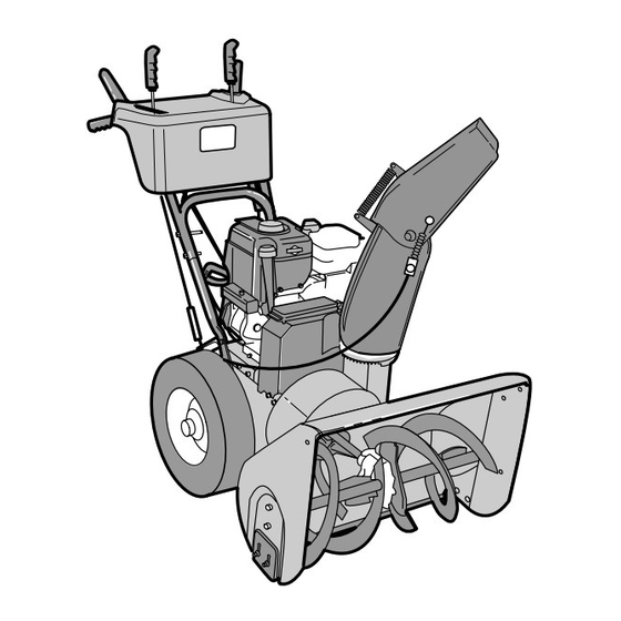
ASSEMBLY Figure 2 shows the snowthrower in the shipping position. Figure 3 shows the snowthrower completely assembled. Reference to right and left hand side of the snowthrower is from the operator’s position at the handle. UNPACKING Figure 2 1. Locate the two tear tabs at the bottom of the carton. Speed Shifter Lever Auger Drive Traction Drive Lever... -
Page 11: Upper Handle And Crank Assembly
ASSEMBLY UPPER HANDLE AND CRANK ASSEMBLY For shipping purposes, the handles were assembled together with the fasteners in the LOWER holes. When Adaptor Boot Bolt assembled, make sure that the fasteners are in the Flatwasher Lockwasher UPPER holes and that the eye bolt is mounted in the LOWER hole on the left side as shown in Figure 5. -
Page 12: Remote Chute Control Knob
ASSEMBLY REMOTE CHUTE CONTROL KNOB 1. Thread the knob onto the lever as far as possible. Make sure that the knob points forward (See Figure 8). 2. Tighten the jam nut against the knob securely. Knob SPEED SELECT KNOB 1. Thread the knob onto the lever as far as possible. Make sure that the knob points forward (See Figure 8). -
Page 13: Snow Chute Assembly
ASSEMBLY SNOW CHUTE ASSEMBLY 1. Remove back carriage bolt (See Figure 11). Chute Deflector 2. Tilt chute back into operating position. Operating Position 3. Replace carriage bolt from inside of chute. 4. Replace flatwasher and nylon locknut on outside of flange. -
Page 14: Operation
OPERATION READ THIS OWNER’S MANUAL AND SAFETY RULES BEFORE OPERATING YOUR SNOWTHROWER. Compare the illustrations with your SNOWTHROWER to familiarize yourself with the location of various controls and adjustments. Save this manual for future reference. Gas Fill Choke Control Remote Chute Control Speed Select Lever Auger Drive Clutch Lever Traction Drive Clutch Lever... -
Page 15: Snowthrower Operation
OPERATION The operation of any snowthrower can result in foreign objects being thrown into the eyes,which can result in severe eye damage. Always wear safety glasses or eye shields before beginning snowthrower Operation. We recommend standard safety glasses or Wide Vision Safety Mask for over spectacles. SNOWTHROWER OPERATION TO THROW SNOW The most effective use of the snowthrower will be established... -
Page 16: Wheel Lock Out Pin
OPERATION WHEEL LOCK OUT PIN 2. For ease of maneuverability when lighter conditions pre- vail, remove klick pin from wheel locked position and in- sert into single wheel drive (unlocked) position 1. The right wheel is secured to the axle with a klick pin. This (Figure 15). -
Page 17: Before Starting Engine
OPERATION BEFORE STARTING ENGINE use leaded gasoline. We recommend that fuel stabilizer be added to the fuel each time that gasoline is added to Check the oil the fuel tank. NOTE: The engine was shipped from the factory filled NOTE: Winter grade gasoline has higher volatility to with oil. -
Page 18: To Stop Engine
OPERATION TO STOP ENGINE WARNING: The electric starter is equipped with a three−wire power cord and plug designed to CAUTION: To stop the engine, do not move the choke operate on 120 volt AC house hold current. The control to CHOKE position. Backfire or engine damage power cord must be properly grounded at all times to can occur. - Page 19 Then, disconnect the power cord from the switch box. If after following the preceding instructions, your engine fails to start, have the engine checked by a John Deere/Frontier dealer. NOTE: Do not lose the safety/ignition key. Keep the safety/ignition key is a safe place. The engine will not start without the safety/ignition key.
-
Page 20: How To Cleara Clogged Discharge Chute
OPERATION FROZEN STARTER WARNING: Never run engine indoors or in en- closed, poorly ventilated areas. Engine exhaust If the starter is frozen and will not turn engine: contains CARBON MONOXIDE, AN ODORLESS AND DEADLY GAS. Keep hands, feet, hair and loose 1. -
Page 21: Operating Tips
OPERATION OPERATING TIPS 1. For optimum snow blower efficiency, adjust ground 6. On gravel or crushed rock surfaces, the skids should be speed, not the throttle. REMEMBER − if the wheels slip, set at 1−1/4 inch (32 mm) below the scraper bar (see To forward speed will be reduced. -
Page 22: Service Recommendations
SERVICE RECOMMENDATIONS SERVICE RECOMMENDATIONS FIRST BEFORE EVERY EVERY EVERY BEGINNING EACH EACH BEFORE PROCEDURE HOUR OFTEN HOURS HOURS HOURS SEASON STORAGE √ Tighten all screws and nuts √ √ Check Traction Clutch √ √ Cable Adjustment (See Cable Adjustment) Check Auger clutch Cable √... -
Page 23: Maintenance
MAINTENANCE Some adjustments will need to be made periodically to properly maintain your snowthrower. All adjustments in the MAINTENANCE section of this manual should be checked at least once each season. SNOWTHROWER The following adjustment should be performed more than once each season. - Page 24 MAINTENANCE LUBRICATION − EVERY 25 HOURS Chute Rotation Gear Chute Rotation Gear Lubricate the chute rotation gear with automotive type oil. (see Figure 27). Figure 27 Chains 4. Lubricate the chains with a chain type lubricant. 5. Wipe the hexshaft and sprockets with 5W30 motor oil. 1.
-
Page 25: Engine
MAINTENANCE ENGINE Check Crankcase Oil Level before starting engine and after Oil Fill Cap/Dipstick each 5 hours of continuous use (see Figure 29). Add proper motor oil as required. FULL NOTE: Overfilling the engine can affect performance. Tighten the oil fill cap securely to prevent leakage. Change Oil every 25 hours of operation or at least once a year, even if the snowthrower is not used for twenty−five hours. -
Page 26: Auger Housing Height Adjustment
MAINTENANCE WARNING: Always turn unit off, remove igni- To adjust skids, proceed as follows: tion key and disconnect the spark plug wire be- 1. Place a block (equal to height from ground desired) un- fore making any repairs or adjustments. der scraper bar near but not under skid. -
Page 27: Belt Adjustment
MAINTENANCE BELT ADJUSTMENT Traction Drive Belt The traction drive belt has constant spring pressure and does not require an adjustment. If the traction drive belt is slipping, replace the belt. See “How To Replace The Belts” in the Maintenance section. Auger Drive Belt If your snowthrower will not discharge snow, check the control cable adjustment. -
Page 28: How To Replace The Belts
MAINTENANCE HOW TO REPLACE THE BELTS The drive belts are of special construction and must be 16. Install the belt cover. Tighten screw (See Figure 32). replaced with original factory replacement belts available 17. Check the adjustment of the cables. See “How To Check from your nearest authorized service center. - Page 29 MAINTENANCE Traction Drive Belt Engine Pulley Belt Guide Auger Drive Pulley Traction Drive Idler Pulley Auger Drive Belt Idler Pulley Traction Drive Spring Traction Drive Belt E−Ring Traction Drive Pulley Swing Plate Axle Rod Engine Pulley Figure 36 MTF−051057L...
- Page 30 MAINTENANCE How To Remove the Traction Drive Belt If the snow thrower will not move forward, check the traction 11. Install and adjust the auger drive belt. See “How To Re- drive belt for wear or damage. If the traction drive belt is worn move The Auger Drive Belt”...
-
Page 31: Belt Guide Adjustment
MAINTENANCE BELT GUIDE ADJUSTMENT 1. Remove spark plug wire. 2. Have someone engage auger drive. 3. Measure the distance between the belt guide and belt. Belt Guide The distance should be 1/8 inch (3.175 mm) for guide. See Figure 38. 1/8 Inch (3.175 mm) 4. -
Page 32: Traction Drive Cable Adjustment
MAINTENANCE Traction Drive Cable Adjustment WARNING: Drain the gasoline outdoors, away from fire or flame. 1. Remove the gas from the gas tank. Stand the snow thrower up on the front end of the auger housing. Traction Drive Cable 2. Loosen the bolts on each side of the bottom panel (see Figure 40). -
Page 33: How To Adjust Or Replace The Friction Wheel
MAINTENANCE HOW TO ADJUST OR REPLACE 5. Tighten the jam nut. THE FRICTION WHEEL 6. Install the bottom panel (see Figure 43). How To Check The Friction Wheel If the snow thrower will not move forward, check the traction 7. Tighten the bolts on each side of the bottom panel. drive belt, the traction drive cable or the friction wheel. - Page 34 MAINTENANCE How To Replace The Friction Wheel If the friction wheel is worn or damaged, the snow thrower will not move forward. The friction wheel must be replaced as follows. Drive Sprocket Axle 1. Remove the gas from the gas tank. Stand the snow thrower up on the front end of the auger housing (4).
- Page 35 MAINTENANCE 10. Remove the three fasteners that hold the friction wheel to the hub (see Figure 49). 11. Remove the friction wheel from the hub. Slip the fric- tion wheel off the hex shaft. Washer 12. Assemble the new friction wheel onto hub with the fas- teners removed earlier.
-
Page 36: How To Remove The Snow Hood
MAINTENANCE HOW TO REMOVE THE SNOW HOOD To access the spark plug, the snow hood must be removed as follows: 1. Remove the choke control knob (see Figure 51). 2. Remove the ON/OFF key. 3. Remove the four mounting screws. 4. -
Page 37: Auger Shear Bolt Replacement
MAINTENANCE AUGER SHEAR BOLT REPLACEMENT The augers are secured to the auger shaft with special bolts NOTE: The spacer fits into the larger hole in the auger that are designed to break if an object becomes lodged in the tube. auger housing. -
Page 38: Storage
STORAGE OFF SEASON STORAGE 4. Thoroughly clean the snowthrower. 5. Lubricate all lubrication points (see “Lubrication“ in the WARNING: Never store the engine, with fuel in the tank, indoors or in a poor ventilated enclo- Maintenance s ection). sure where fuel fumes could reach an open 6. -
Page 39: Trouble Shooting Chart
If you have any questions concerning parts, service, or technical data, contact your nearest John Deere/Frontier dealer. For complete warranty information refer to the warranty in the Owner’s Information section of this manual. -
Page 40: Replacement Parts
REPLACEMENT PARTS WE RECOMMEND JOHN DEERE/FRONTIER quality parts and lubricants available at your John Deere/Frontier dealer. PART NUMBERS MAY CHANGE. When you order re- placement parts, use the part numbers listed below and on the following pages. If a part number changes, your John Deere/Frontier dealer will have the latest part number. -
Page 41: Parts Schematics
FRONTIER MODEL ST0927 FACTORY MODEL 627954x16A ENGINE 25−2 Á Á 25−1 Á 25−3 25−4 25−2 Ref.Drive Page Ref. Auger Housing Page Key No. Part No. Description Key No. Part No. Description MT6219 CORD, STARTER MT53704 SPRING, IDLER TRACTION DRIVE − − − − −... - Page 42 FRONTIER MODEL ST0927 FACTORY MODEL 627954x16A FRAME Ref. Engine Page Ref. Auger Housing Page Ref. Drive Page MTF−051057L...
- Page 43 FRONTIER MODEL ST0927 FACTORY MODEL 627954x16A FRAME Key No. Part No. Description MT1501055E701 COVER, BOTTOM MT310169 SCREW, 1/4−20X .63 MT1501369 YZ IDLER ASSEMBLY, AUGER MT711682 PIN, HAIR .38DIAX1.64LG MT761761 PIN, CLEVIS 3/16” DIA MT165x159 SPRING, TENSION MT761675 YZ ASSY., SPRING ATTACH MT585781 BOLT, 3/8−16X1.25 CARR.
- Page 44 FRONTIER MODEL ST0927 FACTORY MODEL 627954x16A DRIVE Ref. Handle Page Ref. Frame Page Ref. Wheel Page Ref. Wheel Page Ref. Wheel Page Ref. Wheel Page MTF−051057L...
- Page 45 FRONTIER MODEL ST0927 FACTORY MODEL 627954x16A DRIVE Key No. Part No. Description MT1501092 YZ LF AXLE, SWING PLATE YZ MT579851 CHAIN, ROLLER #420x19.00 MT334163 BEARING AND RETAINER, ASSY MT579858 WASHER MT25x020 SCREW, TAP 5/16−18x0.5 MT1501100 ASSY, HEX SHAFT MT579868 CHAIN, ROLLER #420x18.00 LG...
- Page 46 FRONTIER MODEL ST0927 FACTORY MODEL 627954x16A AUGER HOUSING Ref. Gear Case Page MTF−051057L...
- Page 47 FRONTIER MODEL ST0927 FACTORY MODEL 627954x16A AUGER HOUSING Key No. Part No. Description MT583146 PULLEY, 4L 8.40 OD MT2001022 KEY, SQUARE 3/16 X 3/4 MT15x112 NUT, 1/2−20 MT1501158 SPACER, FRICTION PULLEY MT582957 YZ RETAINER, BALL BRNG MT1501389 BEARING, BALL MT001X92 BOLT, HEX 5/16−18X .50...
- Page 48 FRONTIER MODEL ST0927 FACTORY MODEL 627954x16A GEAR CASE Key No. Part No. Description Key No. Part No. Description MT896 CASE, GEAR, RH MT73905 KEY, WOODRUFF #91 MT895 CASE, GEAR, LH MT53737 RING, QUAD 0.924 ID MT910828 SCREW, 5/16−24 x 1.00...
- Page 49 FRONTIER MODEL ST0927 FACTORY MODEL 627954x16A REMOTE CONTROL Ref. Control Panel Ref. Engine Mount Bolt Ref. Upper Chute Ref. Lower Chute Key No. Part No. Description Key No. Part No. Description MT318468 TENSION SPRING MT1001221 TRIM STRIP, BLACK MT310088 BOLT, SHOULDER...
- Page 50 FRONTIER MODEL ST0927 FACTORY MODEL 627954x16A DISCHARGE CHUTE Pop Rivets Ref. Auger Housing Page MTF−051057L...
- Page 51 FRONTIER MODEL ST0927 FACTORY MODEL 627954x16A DISCHARGE CHUTE Key No. Part No. Description MT761168E701 CHUTE, UPPER W/REMOTE MT578088 SCREW, 5/16−18 X.75 MT12021 WASHER, PLASTIC MT71038 MT578088 SCREW, 5/16−18 X.75 MT6711 WASHER, PLASTIC MT71038 MT761169E701 CHUTE, LOWER W/REMOTE MT2x100 BOLT MT71071...
- Page 52 FRONTIER MODEL ST0927 FACTORY MODEL 627954x16A HANDLE Ref. Engine Page MTF−051057L...
- Page 53 FRONTIER MODEL ST0927 FACTORY MODEL 627954x16A HANDLE Key No. Part No. Description Key No. Part No. Description MT1501378E701 ASSY, HANDLE MT71072 WASHER, FLAT MT7288 SCREW MT71046 NUT, HEX MT71072 WASHER, FLAT MT71045 NUT, HEX MT71062 WASHER MT306689 KNOB, SHIFT MT71044...
- Page 54 FRONTIER MODEL ST0927 FACTORY MODEL 627954x16A CHUTE ROD Ref. Handle Assy 852−9 852−5 852−13 852−8 Ref. Auger Housing Assy 852−10 852−11 852−1 852−2 852−6 852−7 852−3 MTF−051057L...
- Page 55 FRONTIER MODEL ST0927 FACTORY MODEL 627954x16A CHUTE ROD Key No. Part No. Description 852−1 MT1501533 YZ ASSEMBLY, YOKE & ROD 852−2 MT164x37 SPRING 852−3 MT1501067 GEAR, CHUTE ROTATION 9T 852−5 MT579493 PIN, COTTER 852−6 MT1501306E701 BRACKET, CHUTE GEAR 852−7 MT1501293 PIN, HAIR 852−8...
- Page 56 FRONTIER MODEL ST0927 FACTORY MODEL 627954x16A CONTROL PANEL Ref.Key# 741 Ref.Key# 790 Ref. Key# 791 Ref. Upper Handle Key No. Part No. Description MT1501358E701 CLUTCH HANDLE LH MT1501357E701 CLUTCH HANDLE RH MT337380 GRIP, CLUTCH LEVER MT1501415 PANEL, CONTROL MT316042 SCREW MT905531 BOLT, 1/4−20 X 0.50...
- Page 57 FRONTIER MODEL ST0927 FACTORY MODEL 627954x16A HEADLIGHT Ref. Control Panel Page Ref. Handle Page Key No. Part No. Description MT762343 LIGHT, HALOGEN MT1501455 HARNESS, WIRE MT071372 TIE, CABLE MT1501412 BRACKET, LIGHT MT901696 SCREW #8 X .50 MT901736 WASHER, FLAT MT1501543...
- Page 58 FRONTIER MODEL ST0927 FACTORY MODEL 627954x16A WHEELS Ref. Drive Page Key No. Part No. Description MT1501563 SHAFT, AXLE MT1501089 SPRKT & HUB MT01x193 SCREW, 1/4−20 x 1.75 MT15x145 NUT, 1/4−20 HEX NYLOCK MT1501114 BEARING, AXLE MT0017x83 FLATWASHER MT1501138 BUSHING, WHEEL MT1501826 TIRE &...
- Page 59 FRONTIER MODEL ST0927 FACTORY MODEL 627954x16A DECALS Key No. Part No. Description MT48x5294 DECAL, SINGLE HAND CONTROL MT7390 DECAL, V−BELTS MT7859 DECAL, OVER ADJUSTMENT MT48x5967 DECAL, ROTATING AUGER MT48x5578 DECAL, DANGER MT48x5965 DECAL, UNCLOGGING CHUTE MT48x5291 DECAL, SPEED CONTROL MT48x5292...
-
Page 60: Specifications
SPECIFICATIONS ST0927 Engine Briggs & Stratton Intek Snow OHV Horsepower 9.5 hp Starter Electric / Recoil Fuel Capacity 4 quarts Drive System Friction Disc Speeds 6 Forward / 2 Reverse 16” Tire Diameter Traction Control Pin Lock Clearing Width 27”...
Need help?
Do you have a question about the ST0927 and is the answer not in the manual?
Questions and answers