Table of Contents
Advertisement
Advertisement
Table of Contents

Related Manuals for Frontier ST0524


Summary of Contents for Frontier ST0524
-
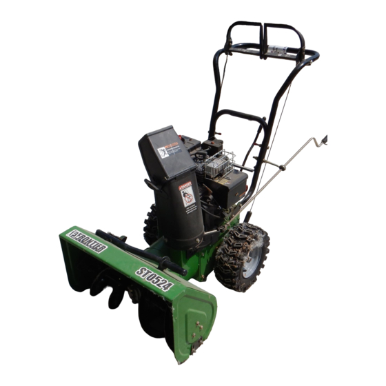
Page 1: Snow Thrower
ST0524 Snow Thrower OPERATOR’S MANUAL MTF-031072L... -
Page 2: Responsibility Of The Owner
INTRODUCTION Congratulations on your purchase of a Frontier Snowthrower. It has been designed, engineered and manufactured to give you the best possible dependability and performance. However, like all mechanical products, your machine will occasionally re- quire adjustment and maintenance. This handbook should be read before operating or performing and adjustments on your machine. -
Page 3: Rules For Safe Operation
RULES FOR SAFE OPERATION IMPORTANT WARNING: Always disconnect the spark plug wire and place it where it cannot make contact with spark plug to prevent accidental starting during: Preparation, Maintenance, or Storage of your snowthrower. Safe Operation Practices for Snowthrowers As Recommended By: American National Standards Institute. -
Page 4: Maintenance And Storage
RULES FOR SAFE OPERATION 7. Stop the engine (motor) whenever you leave the operat- Maintenance And Storage ing position, before unclogging the auger/impeller hous- 1. Check shear bolts and other bolts at frequent intervals ing or discharge chute and when making any repairs, for proper tightness to be sure the equipment is in safe adjustments, or inspections. -
Page 5: Table Of Contents
TABLE OF CONTENTS SAFETY DECALS ..........WARRANTY . -
Page 6: Safety Decals
SAFETY DECALS the meaning, then thoroughly read all safety and operation WARNING: If safety decals are dam- instructions in this Owner’s Manual or contact your local aged or missing, replace immediately. dealer. If any safety decals become worn or damaged and cannot Look for this symbol to indicate important safe- be read, order replacement decals from your local dealer. -
Page 7: Warranty
THREE YEAR LIMITED WARRANTY Murray warrants to the original purchaser of this Frontier Branded Snowthrower that this unit shall be free from defects in material and workmanship under normal use and service for a period of Three (3) Year from the date of purchase; however,... -
Page 8: Assembly
ASSEMBLY TOOLS REQUIRED FOR ASSEMBLY CONTENTS OF SHIPPING CARTON 1 - Knife 1- Snowthrower 2 - 1/2” wrenches (or adjustable wrenches) 1- Container of Fuel Stabilizer (Located in Parts Bag) 2 - 9/16” wrenches (or adjustable wrenches) 1- Crank Assembly 2 - 3/4”... -
Page 9: Unpacking
ASSEMBLY Figure 2 shows the snowthrower in the shipping position. Figure 3 shows the snowthrower completely assembled. Reference to right and left hand side of the snowthrower is from the operator’s position at the handle. UNPACKING Figure 2 1. Locate the two tear tabs at the bottom of the carton. Auger Drive Traction Drive Lever 2. -
Page 10: Upper Handle And Crank Assembly
ASSEMBLY UPPER HANDLE AND CRANK ASSEMBLY Crank 1. Loosen, but do not remove the screws, flatwashers, lock- 5/16-18x2” washers and hex nuts in the upper holes of the lower han- Bolt dle. 5/16-18” Lockwasher 3/8” Nylon 2. Remove the fasteners and the crank assembly eyebolt 5/16-18”... -
Page 11: Shifter Lever Knob Assembly
ASSEMBLY SHIFTER LEVER KNOB ASSEMBLY Shifter Knob 1. Thread the shifter knob onto the threaded end of the shifter lever until it is snug against the hex nut and the lip is pointed away from the engine (See Figure 8). On Hex Nut some models, the shifter knob is attached. -
Page 12: Operation
OPERATION READ THIS OWNER’S MANUAL AND SAFETY RULES BEFORE OPERATING YOUR SNOWTHROWER. Compare the illustrations with your SNOWTHROWER to familiarize yourself with the location of various controls and adjustments. Save this manual for future reference. Traction Drive Clutch Lever Auger Drive Clutch Lever Gas Fill Electric Start Button... -
Page 13: Snowthrower Operation
OPERATION The operation of any snowthrower can result in foreign objects being thrown into the eyes,which can result in severe eye damage. Always wear safety glasses or eye shields before beginning snowthrower Operation. We recommend standard safety glasses or Wide Vision Safety Mask for over spectacles. SNOWTHROWER OPERATION 4. -
Page 14: Wheel Lock Out Pin
OPERATION TO THROW SNOW WARNING: Never run engine indoors or in an 1. Push down the auger driver lever (right hand). See enclosed, poor ventilated area. Engine exhaust Figure 10. contains CARBON MONOXIDE, 2. To stop throwing snowl, release the auger drive lever. DERLESS and DEADLY GAS. -
Page 15: How To Remove Snow From Auger
OPERATION HOW TO REMOVE SNOW FROM AUGER WARNING: Do not attempt to remove snow or debris that may become lodged in auger with- out taking the following precautions: A cleaning stick is attached to the top of the auger housing. Use the cleaning stick to remove snow from the auger housing. -
Page 16: Before Starting Engine
OPERATION BEFORE STARTING ENGINE WARNING: Gasoline is flammable. Always use caution when handling or storing gasoline. Do Check the oil not add gasoline to the fuel tank while snow- NOTE: The engine was shipped from the factory filled thrower is running, hot, or when snowthrower is in an with oil. -
Page 17: To Start Engine
OPERATION NOTE: The normal sound made by spinning the NOTE: Allow the engine to warm up for several starter will not harm the engine or the starter. minutes before blowing snow in temperatures below 0°F (-18_ C). 3. Disconnect the power cord from the receptacle first and 8. -
Page 18: Use Of Electric Starter
OPERATION USE OF ELECTRIC STARTER On models so equipped Starter Button WARNING: The electric starter is equipped with a three-wire power cord and plug designed to operate on 120 volt AC house hold current. The power cord must be properly grounded at all times to Switch Box avoid the possibility of electric shock which can cause injury to the operator. - Page 19 If, after following the preceding instructions, your engine fails e. Disconnect the POWER CORD from the receptacle to start, have it checked by a John Deere/Frontier dealer. first and then from the SWITCH BOX. 8. Run the engine at or near top speed.
-
Page 20: Operating Tips
OPERATION OPERATING TIPS 9. Before starting snowthrower, always inspect augers and impeller for ice accumulation and/or debris, which could 1. For optimum snowthrower efficiency, adjust ground result in snowthrower damage. speed, not the throttle. REMEMBER - if the wheels slip, forward speed will be reduced. -
Page 21: Service Recommendations
SERVICE RECOMMENDATIONS SERVICE RECOMMENDATIONS FIRST BEFORE EVERY EVERY EVERY BEGINNING EACH EACH BEFORE PROCEDURE HOUR OFTEN HOURS HOURS HOURS SEASON STORAGE √ √ √ Tighten all screws and nuts Check Traction Clutch √ √ Cable Adjustment (See Cable Adjustment) Check Auger clutch Cable √... -
Page 22: Maintenance
MAINTENANCE Some adjustments will need to be made periodically to Remove filler plug (Figure 20), once a year. If grease is properly maintain your snowthrower. visible, do not add. If grease is not visible, use a piece of fine wire, like a dipstick to check if there is grease in the gear box. All adjustments in the MAINTENANCE section of this manual Mobilux EP1 and Shell Aldania EP1 are suitable equivalents. - Page 23 MAINTENANCE LUBRICATION - EVERY 25 HOURS Chute Rotation Gear Chute Rotation Gear Lubricate the chute rotation gear with automotive type oil. (see Figure 21). Figure 21 Chains 4. Lubricate the chains with a chain type lubricant. 5. Wipe the hexshaft and sprockets with 5W30 motor oil. 1.
-
Page 24: Engine
MAINTENANCE ENGINE Check Crankcase Oil Level before starting engine and after each 5 hours of continuous use (see Figure 23). Add proper motor oil as required. NOTE: Overfilling the engine can affect performance. Tighten the oil fill cap securely to prevent leakage. Change Oil every 25 hours of operation or at least once a year, even if the snowthrower is not used for twenty-five hours. -
Page 25: Auger Housing Height Adjustment
MAINTENANCE WARNING: Always turn unit off, remove igni- To adjust skids, proceed as follows: tion key and disconnect the spark plug wire be- 1. Place a block (equal to height from ground desired) un- fore making any repairs or adjustments. der scraper bar near but not under skid. -
Page 26: Belt Adjustment
MAINTENANCE BELT ADJUSTMENT Traction Drive Belt The traction drive belt has constant spring pressure and does not require an adjustment. If the traction drive belt is slipping, replace the belt. See “How To Replace The Belts” in the Maintenance section. Auger Drive Belt If your snowthrower will not discharge snow, check the control cable adjustment. -
Page 27: How To Replace The Belts
MAINTENANCE HOW TO REPLACE THE BELTS 9. Adjust the auger drive belt. See “How To Adjust The Au- ger Drive Belt” in the Maintenance section. 10. Adjust the belt guide. See “How To Adjust The Belt The drive belts are of special construction and must be Guide”... - Page 28 MAINTENANCE How To Remove the Traction Drive Belt If the snow thrower will not move forward, check the traction 11. Install and adjust the auger drive belt. See “How To Re- drive belt for wear or damage. If the traction drive belt is worn move The Auger Drive Belt”...
-
Page 29: Belt Guide Adjustment
MAINTENANCE BELT GUIDE ADJUSTMENT 1. Remove spark plug wire. Belt Guide 2. Have someone engage auger drive. 1/8 Inch (3.175 mm) 3. Measure the distance between the belt guide and belt. The distance should be 1/8 inch (3.175 mm) for guide. Auger Idler Pulley Engaged See Figure 31. -
Page 30: Traction Drive Cable Adjustment
MAINTENANCE Traction Drive Cable Adjustment Bolt WARNING: Drain the gasoline outdoors, away Bottom Panel from fire or flame. 1. Remove the gas from the gas tank. Stand the snow Auger Housing thrower up on the front end of the auger housing. 2. -
Page 31: How To Adjust Or Replace The Friction Wheel
MAINTENANCE HOW TO ADJUST OR REPLACE 5. Install the bottom panel (see Figure 37). THE FRICTION WHEEL 6. Tighten the bolts on each side of the bottom panel. How To Check The Friction Wheel If the snow thrower will not move forward, check the traction Bolt Bottom Panel drive belt, the traction drive cable or the friction wheel. - Page 32 MAINTENANCE How To Replace The Friction Wheel If the friction wheel is worn or damaged, the snow thrower will not move forward. The friction wheel must be replaced as Drive follows. Sprocket Axle 1. Remove the gas from the gas tank. Stand the snow thrower up on the front end of the auger housing (4).
- Page 33 MAINTENANCE 10. Remove the three fasteners that hold the friction wheel to the hub (see Figure 43). 11. Remove the friction wheel from the hub. Slip the fric- tion wheel off the hex shaft. Washer 12. Assemble the new friction wheel onto hub with the fas- teners removed earlier.
-
Page 34: Auger Shear Bolt Replacement
MAINTENANCE AUGER SHEAR BOLT REPLACEMENT The augers are secured to the auger shaft with special bolts that are designed to break if an object becomes lodged in the auger housing. Use of a harder bolt will reduce the protection provided by the shear bolt. To replace a broken shear bolt, Shear Pin proceed as follows: WARNING: To insure safety and performance... -
Page 35: Storage
STORAGE OFF SEASON STORAGE 4. Thoroughly clean the snowthrower. 5. Lubricate all lubrication points (see “Lubrication“ in the WARNING: Never store the engine, with fuel in Maintenance section). the tank, indoors or in a poor ventilated enclo- sure where fuel fumes could reach an open 6. -
Page 36: Trouble Shooting Chart
If you have any questions concerning parts, service, or technical data, contact your nearest John Deere/Frontier dealer. For complete warranty information refer to the warranty in the Owner’s Information section of this manual. -
Page 37: Replacement Parts
REPLACEMENT PARTS WE RECOMMEND JOHN DEERE/FRONTIER quality parts and lubricants available at your John Deere/Frontier dealer. PART NUMBERS MAY CHANGE. When you order re- placement parts, use the part numbers listed below and on the following pages. If a part number changes, your John Deere/Frontier dealer will have the latest part number. - Page 38 FRONTIER MODEL ST0524 FACTORY MODEL 624504x16A ENGINE 25-2 Á Á 25-1 Á Á 25-3 25-4 25-2 Ref. Drive Page Ref. Auger Housing Page Key No. Part No. Description Key No. Part No. Description ------ ENGINE MT710097 SCREW 5/16-24 X 0.75...
-
Page 39: Parts Schematics
FRONTIER MODEL ST0524 FACTORY MODEL 624504x16A ELECTRIC START ASSEMBLY Part No. Description MT330783 MOTOR, STARTER MT762226 SCREW MT6217 SCREW MT6219 CORD, STARTER MTF-031072L... - Page 40 FRONTIER MODEL ST0524 FACTORY MODEL 624504x16A FRAME Ref. Engine Page Ref. Auger Housing Page Ref. Drive Page MTF-031072L...
- Page 41 FRONTIER MODEL ST0524 FACTORY MODEL 624504x16A FRAME Key No. Part No. Description MT1501055E701 COVER, BOTTOM MT310169 SCREW, 1/4-20X .63 MT1501111 YZ IDLER ASSEMBLY, AUGER MT711682 PIN, HAIR .38DIAX1.64LG MT761761 PIN, CLEVIS 3/16” DIA MT165x160 SPRING, TENSION MT761675 YZ ASSY., SPRING ATTACH MT585781 BOLT, 3/8-16X1.25 CARR.
- Page 42 FRONTIER MODEL ST0524 FACTORY MODEL 624504x16A DRIVE Ref. Shift Yoke Page Ref. Frame Page Ref. Wheel Page Ref. Wheel Page Ref. Wheel Page Ref. Wheel Page MTF-031072L...
- Page 43 FRONTIER MODEL ST0524 FACTORY MODEL 624504x16A DRIVE Key No. Part No. Description MT1501092 YZ LF AXLE, SWING PLATE YZ MT579851 CHAIN, ROLLER #420x19.00 MT334163 BEARING AND RETAINER, ASSY MT579858 WASHER MT780055 SCREW, TAP 5/16-18x0.5 MT1501100 ASSY, HEX SHAFT MT579868 CHAIN, ROLLER #420x18.00 LG...
- Page 44 FRONTIER MODEL ST0524 FACTORY MODEL 624504x16A AUGER HOUSING Ref. Gear Case Page MTF-031072L...
- Page 45 FRONTIER MODEL ST0524 FACTORY MODEL 624504x16A AUGER HOUSING Key No. Part No. Description MT762146 PULLEY, 4L 6.12X .67 MT577400 SCREW, 5/16-18X.63 MT2001022 KEY, SQUARE 3/16 X 3/4 MT1501158 SPACER, FRICTION PULLEY MT582957 YZ RETAINER, BALL BRNG MT43846 BEARING, BALL MT001X92 BOLT, HEX 5/16-18X .50...
- Page 46 FRONTIER MODEL ST0524 FACTORY MODEL 624504x16A HANDLE ASSEMBLY MTF-031072L...
- Page 47 FRONTIER MODEL ST0524 FACTORY MODEL 624504x16A HANDLE ASSEMBLY Key No. Part No. Description MT9552E701 HANDLE MT11234 SCREW MT71071 WASHER, FLAT MT71060 WASHER MT15x144 MT11261 PLASTIC-ST OP MT302557 CLUTCH, LEFT HANDLE CONTROL MT302558 CLUTCH, RIGHT HANDLE CONTROL MT12621 ROD, PIVOT HANDLE...
- Page 48 FRONTIER MODEL ST0524 FACTORY MODEL 624504x16A SHIFT YOKE Key No. Part No. Description MT581631E701 ROD, SHIFT MT302628 SCREW, 1/4-20X.75 MT73826 NUT, 1/4-20 MT318486 NUT, JAM MT304438 KNOB MT760564 LEVER, SPRING MT302628 SCREW, 1/4-20X.75 MT73826 NUT, 1/4-20 MT579944 BEARING, FLANGED MT1501085 YZ ROD ASSY., SPEED SELECT...
- Page 49 FRONTIER MODEL ST0524 FACTORY MODEL 624504x16A DISCHARGE CHUTE Ref. Auger Housing Page Key No. Part No. Description MT2x100 SCREW, 5/16-18 X 1.00 MT71071 WASHER, FLAT MT71038 NUT, 5/16-18 MT71071 WASHER MT57171 KNOB, T 3.00 MT15X144 NUT, 5/16-18 MT2x100 BOLT, 5/16-18X1..00...
- Page 50 FRONTIER MODEL ST0524 FACTORY MODEL 624504x16A CHUTE ROD Ref. Handle Assy 852-9 852-5 852-8 852-13 852-10 Ref. Auger Housing Assy 852-1 1 852-1 852-2 852-6 852-4 852-7 852-3 Key No. Part No. Description Key No. Part No. Description 852-1 MT1501309 YZ ASSEMBLY, YOKE &...
- Page 51 FRONTIER MODEL ST0524 FACTORY MODEL 624504x16A WHEELS Ref. Drive Page Key No. Part No. Description MT1501562 SHAFT, AXLE MT1501089 SPRKT & HUB MT01x193 SCREW, 1/4-20 x 1.75 MT15x145 NUT, 1/4-20 HEX NYLOCK MT1501114 BEARING, AXLE MT712120 FLATWASHER MT1501139 BUSHING, WHEEL MT1501656 TIRE &...
- Page 52 FRONTIER MODEL ST0524 FACTORY MODEL 624504x16A GEAR CASE Key No. Part No. Description MT10577 CASE, GEAR, RH MT10576 CASE, GEAR, LH MT710025 SCREW,1/4-20X.75 MT15X143 NUT,1/4-20 MT9344 SCREW, 3/8-16X.50 MT9566 SEAL, OIL MT50304 BEARING, FL MT48275 WASHER, FLAT MT340286 SHAFT, AUGER OUTPUT...
- Page 53 FRONTIER MODEL ST0524 FACTORY MODEL 624504x16A DECALS Key No. Part No. Description MT48x5283 DECAL, AUGER CONTROL MT7390 DECAL, V-BELTS MT7859 DECAL, OVER ADJUSTMENT MT48x5286 DECAL, ROTATING AUGER MT761078 DECAL, DANGER MT48x5285 DECAL, UNCLOGGING CHUTE MT48x5284 DECAL, SPEED CONTROL MT760983 DECAL, SHEAR BOLTS...
- Page 54 NOTES MTF-031072L...
- Page 55 NOTES MTF-031072L...
-
Page 56: Specifications
SPECIFICATIONS ST0524 Engine Tecumseh Snow King Horsepower 5 hp Starter Electric / Recoil Fuel Capacity 2 quarts Drive System Friction Disc Speeds 6 Forward / 2 Reverse Tire Diameter 13” Traction Control Pin Lock Clearing Width 24” Housing Height 17.5”...
Need help?
Do you have a question about the ST0524 and is the answer not in the manual?
Questions and answers