Thermal Dynamics CUTMASTER Operating Manual
35mm-40mm plasma cutting system
Hide thumbs
Also See for CUTMASTER:
- Service manual (128 pages) ,
- Operating manual (84 pages) ,
- Operating manual (66 pages)

Related Manuals for Thermal Dynamics CUTMASTER


Summary of Contents for Thermal Dynamics CUTMASTER
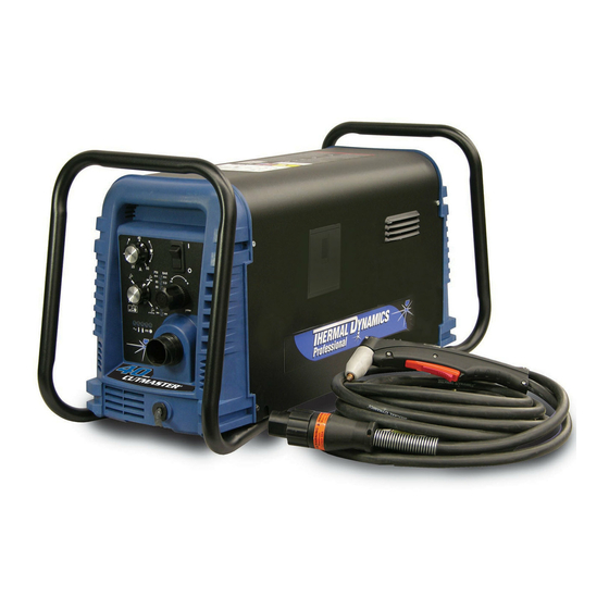
- Page 1 35mm 40mm CUTMASTER ™ PLASMA CUTTING SYSTEM A-08622 Operating Manual Rev. AA Date: October 30, 2008 Manual # 0-5118 Operating Features: 380- 35mm 380- 40mm...
- Page 2 YOU ARE IN GOOD COMPANY! The Brand of Choice for Contractors and Fabricators Worldwide. Thermal Dynamics is a Global Brand of manual and automation Plasma Cutting Products for Thermadyne Industries Inc. We distinguish ourselves from our competition through market- leading, dependable products that have stood the test of time.
- Page 3 While the information contained in this Manual represents the Manufacturer's best judgement, the Manufacturer assumes no liability for its use. Plasma Cutting Power Supply CutMaster™ 35mm SL60 1 Torch™ Operating Manual No.: 0-5118 CutMaster™ 40mm SL60 1 Torch™...
-
Page 4: Table Of Contents
TABLE OF CONTENTS SECTION 1: GENERAL INFORMATION .................1-1 1.01 Notes, Cautions and Warnings ..............1-1 1.02 Important Safety Precautions ..............1-1 1.03 Publications....................1-2 1.04 Note, Attention et Avertissement ..............1-3 1.05 Precautions De Securite Importantes ............1-3 1.06 Documents De Reference ................1-4 1.07 Declaration of Conformity ................1-6 1.08 Statement of Warranty ................1-7 SECTION 2 SYSTEM: INTRODUCTION ................2-1... - Page 5 TABLE OF CONTENTS SECTION 5 SYSTEM: SERVICE ....................5-1 5.01 General Maintenance .................5-1 5.02 Maintenance Schedule ................5-2 5.03 Common Faults ...................5-2 5.04 Fault Indicator .....................5-3 5.05 Basic Troubleshooting Guide ..............5-4 SECTION 5 TORCH: SERVICE ..................... 5T-1 5T.01 General Maintenance ................5T-1 5T.02 Inspection and Replacement of Consumable Torch Parts ......
- Page 6 TABLE OF CONTENTS This Page Intentionally Blank.
-
Page 7: Section 1: General Information
CUTMASTER 35mm, 40mm SECTION 1: • The kinds of fumes and gases from the plasma arc depend on the kind of metal being used, coatings on the metal, and the different processes. You must be very careful when cutting GENERAL INFORMATION... -
Page 8: Publications
CUTMASTER 35mm, 40mm 1.03 Publications • Do not cut or weld on containers that may have held com- bustibles. Refer to the following standards or their latest revisions for more • Provide a fire watch when working in an area where fire information: hazards may exist. -
Page 9: Note, Attention Et Avertissement
CUTMASTER 35mm, 40mm 14. American Welding Society Standard AWSF4.1, RECOM- MENDED SAFE PRACTICES FOR THE PREPARATION FOR WELDING AND CUTTING OF CONTAINERS AND PIPING FUMÉE et GAZ THAT HAVE HELD HAZARDOUS SUBSTANCES, obtainable La fumée et les gaz produits par le procédé de jet de plasma peuvent from the American Welding Society, 550 N.W. -
Page 10: Documents De Reference
CUTMASTER 35mm, 40mm • Montez et maintenez le matériel conformément au Code élec- • Utilisez la nuance de lentille qui est suggèrée dans le recom- trique national des Etats-Unis. (Voir la page 5, article 9.) mendation qui suivent ANSI/ASC Z49.1: •... - Page 11 CUTMASTER 35mm, 40mm 4. Norme ANSI Z87.1, PRATIQUES SURES POUR LA PROTECTION DES YEUX ET DU VISAGE AU TRAVAIL ET DANS LES ECOLES, disponible de l’Institut Américain des Normes Nationales (Ameri- can National Standards Institute), 1430 Broadway, New York, NY 10018 5.
-
Page 12: Declaration Of Conformity
Thermal Dynamics has been manufacturing products for more than 30 years, and will continue to achieve excellence in our area of manufacture. -
Page 13: Statement Of Warranty
Thermal Dynamics will repair or replace, at its discretion, any warranted parts or components that fail due to defects in material or workmanship within the time periods set out below. Thermal Dynamics Corporation must be notified within 30 days of any failure, at which time Thermal Dynamics Corporation will provide instructions on the warranty procedures to be implemented. - Page 14 CUTMASTER 35mm, 40mm This Page Intentionally Blank GENERAL INFORMATION Manual 0-5118...
-
Page 15: Section 2 System: Introduction
Electronic copies of this manual can also be downloaded at no charge in Acrobat PDF format by going to the Thermal Dynamics web site listed below and clicking on Thermal Dynamics and then on the Literature link: http://www.thermal-dynamics.com Manual 0-5118... -
Page 16: Power Supply Specifications
30 - 100 Amps, Continuously Adjustable Output Current Power Supply Gas Particulates to 5 Microns Filtering Ability CutMaster 35 Power Supply Duty Cycle * Duty Cycle Ratings @ 40° C (104° F) Ambient Temperature Opperating Range 0° - 50° C 100%... -
Page 17: Input Wiring Specifications
24" 0.6 m 30.5" 63 lb / 28.6 kg 774.7 m 6" 150 mm 2.05 Input Wiring Specifications CutMaster 35mm Power Supply Input Cable Wiring Requirements Input voltage Freq Power Input Suggested Sizes Flexible Cord Volts I max I eff... -
Page 18: Power Supply Features
CUTMASTER 35mm, 40mm 2.06 Power Supply Features Handle and Leads Wrap Control Panel Torch Leads Receptacle Art # A-08359 Work Cable and Clamp Port for Optional Automation Interface Cable Filter Assembly Gas Inlet Port Art # A-08547 Input Power Cord... -
Page 19: Section 2 Torch: Introduction
CUTMASTER 35mm, 40mm SECTION 2 TORCH: INTRODUCTION 2T.03 Specifications 2T.01 Scope of Manual This manual contains descriptions, operating A. Torch Configurations instructions and maintenance procedures for 1. Hand/Manual Torch, Models the 1Torch Models SL100/Manual and SL100/ The hand torch head is at 75° to the torch han- Mechanized Plasma Cutting Torches. -
Page 20: 04 Options And Accessories
CUTMASTER 35mm, 40mm 2T.04 Options And Accessories F. Torch Ratings For options and accessories, see section 6. Manual Torch Ratings CUTMASTER 35mm 2T.05 Introduction to Plasma 104° F Ambient Temperature 40° C A. Plasma Gas Flow Duty Cycle 100% @ 100 Amps @ 400 scfh... - Page 21 CUTMASTER 35mm, 40mm B. Gas Distribution E. Parts - In - Place (PIP) The single gas used is internally split into plasma The torch includes a 'Parts - In - Place' (PIP) cir- and secondary gases. cuit. When the shield cup is properly installed, it closes a switch.
- Page 22 CUTMASTER 35mm, 40mm This Page Intentionally Blank INTRODUCTION 2T-4 Manual 0-5118...
-
Page 23: Section 3 System: Installation
CUTMASTER 35mm, 40mm SECTION 3 SYSTEM: INSTALLATION 3.01 Unpacking 1. Use the packing lists to identify and account for each item. 2. Inspect each item for possible shipping damage. If damage is evident, contact your distribu- tor and / or shipping company before proceeding with the installation. -
Page 24: Primary Input Power Connections
CUTMASTER 35mm, 40mm 3.03 Primary Input Power Connections CAUTION Check your power source for correct voltage before plugging in or connecting the unit. The primary power source, fuse, and any extension cords used must conform to local electrical code and the recommended circuit protection and wiring requirements as specified in Section 2. -
Page 25: Gas Connections
CUTMASTER 35mm, 40mm 3.04 Gas Connections Connecting Gas Supply to Unit The connection is the same for compressed air or high pressure cylinders. Refer to the following two subsections if an optional air line filter is to be installed. 1. Connect the air line to the inlet port. The illustration shows typical fittings as an example. - Page 26 CUTMASTER 35mm, 40mm NOTE For a secure seal, apply thread sealant to the fitting threads, according to the maker's instructions. Do Not use Teflon tape as a thread sealer, as small particles of the tape may break off and block the small air passages in the torch.
- Page 27 CUTMASTER 35mm, 40mm Installing Optional Two - Stage Air Filter Kit This optional two - stage air line filter is also for use on compressed air shop systems. Filter re- moves moisture and contaminants to at least 5 microns. Connect the air supply as follows: 1.
- Page 28 CUTMASTER 35mm, 40mm Using High Pressure Air Cylinders When using high pressure air cylinders as the air supply: 1. Refer to the manufacturer’s specifications for installation and maintenance procedures for high pressure regulators. 2. Examine the cylinder valves to be sure they are clean and free of oil, grease or any foreign material.
-
Page 29: Section 3 Torch: Installation
/ OFF If necessary, connect the torch to the Power (up) position. Supply. Connect only the Thermal Dynamics 2. Put the Function Control switch in the model SL100 / Manual or SL100 / Mechanical Torch to this power supply. Maximum torch position. - Page 30 CUTMASTER 35mm, 40mm Pinch Block Assembly Square Workpiece A-02585 Mechanical Torch Set - Up 3. The proper torch parts (shield cup, tip, start cartridge, and electrode) must be installed for the type of operation. Refer to Section 4T.07, Torch Parts Selection for details.
-
Page 31: Section 4 System: Operation
CUTMASTER 35mm, 40mm SECTION 4 SYSTEM: OPERATION 4.01 Front Panel Controls / Features See Illustration for numbering Identification 1. Output Current Control Sets the desired output current. Output settings up to 60 Amps may be used for drag cutting (with the torch tip contacting the workpiece) or higher for standoff cutting. -
Page 32: Preparations For Operation
Torch Connection Set Operating Pressure Check that the torch is properly connected. Only 1. Place the Power Supply Function Control Thermal Dynamics model SL100 / Manual or knob to the SET position. Gas will SL100 / Mechanical Torches may be connected to this Power Supply. -
Page 33: Cutting Operation
CUTMASTER 35mm, 40mm Cutting Operation STANDOFF When the torch leaves the workpiece during cut- Gas Pressure Settings ting operations with the Function Control Knob in SL100 the RUN position, there is a brief delay in restart- (Mechanized Torch) ing the pilot arc. With the knob in the RAPID... - Page 34 CUTMASTER 35mm, 40mm This Page Intentionally Blank OPERATION Manual 0-5118...
-
Page 35: Section 4 Torch: Operation
CUTMASTER 35mm, 40mm SECTION 4 TORCH: OPERATION 4T.01 Torch Parts Selection Torch Head Depending on the type of operation to be done determines the torch parts to be used. Type of operation: Electrode Drag cutting, standoff cutting or gouging Torch parts: Start Cartridge... -
Page 36: 02 Cut Quality
CUTMASTER 40mm 4T.02 Cut Quality Bottom Dross Buildup Molten material which is not blown out of the NOTES cut area and resolidifies on the plate. Excessive Cut quality depends heavily on setup and dross may require secondary cleanup operations parameters such as torch standoff, alignment after cutting. -
Page 37: 04 Hand Torch Operation
CUTMASTER 35mm, 40mm Torch Standoff tant cleanup can be accomplished by scraping, not grinding. Improper standoff (the distance between the torch tip and workpiece) can adversely affect tip life as 4T.04 Hand Torch Operation well as shield cup life. Standoff may also signifi- cantly affect the bevel angle. - Page 38 CUTMASTER 40mm 3. Hold the torch away from your body. 8. For a consistent standoff height from the 4. Slide the trigger release toward the back workpiece, install the standoff guide by of the torch handle while simultaneously sliding it onto the torch shield cup. Install squeezing the trigger.
- Page 39 CUTMASTER 35mm, 40mm Drag Cutting With a Hand Torch Trigger Drag cutting works best on metal 1/4" (6 mm) thick or less. NOTE Drag cutting can only be performed at 60 amps Trigger Release or less. For best parts performance and life, always use the correct parts for the type of operation.
-
Page 40: 05 Gouging
CUTMASTER 40mm the pierce off the cutting line and then 4T.05 Gouging continue the cut onto the line. Hold the torch perpendicular to the workpiece after the pierce is complete. WARNINGS 4. Hold the torch away from your body. Be sure the operator is equipped with proper 5. -
Page 41: 06 Mechanized Torch Operation
CUTMASTER 35mm, 40mm Torch Travel Speed Slag Buildup NOTE Slag generated by gouging on materials such as carbon and stainless steels, nickels, and alloyed Refer to Appendix Pages for additional steels, can be removed easily in most cases. Slag information as related to the Power Supply does not obstruct the gouging process if it accumu- used. - Page 42 CUTMASTER 40mm Piercing With Machine Torch To pierce with a machine torch, the arc should be started with the torch positioned as high as possible above the plate while allowing the arc to transfer and pierce. This standoff helps avoid...
-
Page 43: 07 Parts Selection For Sl100Torch Cutting
9-8241 9-8237 Tips: Tip Gouging A 9-8225 (40 Amps Max.) NOTE CutMaster 52 uses 60A and less Tip Gouging B 9-8226 (50 - 100 Amps) CutMaster 82 uses 80A and less CutMaster 102 uses 100A and less Art # A-08065_AC... -
Page 44: 08 Recommended Cutting Speeds For Sl100 Torch With Exposed Tip
CUTMASTER 40mm 4T.08 Recommended Cutting Speeds for SL100 Torch With Exposed Tip Type Torch: SL100 With Exposed Tip Type Material: Mild Steel Type Plasma Gas: Air Type Secondary Gas: Single Gas Torch Thickness Output Amperage Speed (Per Minute) Standoff Plasma Gas Press... - Page 45 CUTMASTER 35mm, 40mm Type Torch: SL100 With Exposed Tip Type Material: Mild Steel Type Plasma Gas: Air Type Secondary Gas: Single Gas Torch Thickness Output Amperage Speed (Per Minute) Standoff Plasma Gas Press Flow (CFH) Pierce Pierce Height Inches mm (Cat. No.) Volts(VDC)
- Page 46 CUTMASTER 40mm Type Torch: SL100 With Exposed Tip Type Material: Mild Steel Type Plasma Gas: Air Type Secondary Gas: Single Gas Torch Thickness Output Amperage Speed (Per Minute) Standoff Plasma Gas Press Flow (CFH) Pierce Pierce Height Inches mm (Cat. No.) Volts(VDC)
- Page 47 CUTMASTER 35mm, 40mm Type Torch: SL100 With Exposed Tip Type Material: Mild Steel Type Plasma Gas: Air Type Secondary Gas: Single Gas Torch Thickness Output Amperage Speed (Per Minute) Standoff Plasma Gas Press Flow (CFH) Pierce Pierce Height Inches mm (Cat. No.) Volts(VDC)
-
Page 48: 09 Recommended Cutting Speeds For Sl100Torch With Shielded Tip
CUTMASTER 40mm 4T.09 Recommended Cutting Speeds for SL100Torch With Shielded Tip Type Torch: SL100 With Shielded Tip Type Material: Mild Steel Type Plasma Gas: Air Type Secondary Gas: Single Gas Torch Thickness Output Amperage Speed (Per Minute) Standoff Plasma Gas Press... - Page 49 CUTMASTER 35mm, 40mm Type Torch: SL100 With Shielded Tip Type Material: Mild Steel Type Plasma Gas: Air Type Secondary Gas: Single Gas Torch Thickness Output Amperage Speed (Per Minute) Standoff Plasma Gas Press Flow (CFH) Pierce Pierce Height Inches mm (Cat. No.) Volts(VDC)
- Page 50 CUTMASTER 40mm Type Torch: SL100 With Shielded Tip Type Material: Mild Steel Type Plasma Gas: Air Type Secondary Gas: Single Gas Torch Thickness Output Amperage Speed (Per Minute) Standoff Plasma Gas Press Flow (CFH) Pierce Pierce Height Inches mm (Cat. No.) Volts(VDC)
- Page 51 CUTMASTER 35mm, 40mm Type Torch: SL100 With Shielded Tip Type Material: Mild Steel Type Plasma Gas: Air Type Secondary Gas: Single Gas Torch Thickness Output Amperage Speed (Per Minute) Standoff Plasma Gas Press Flow (CFH) Pierce Pierce Height Inches mm (Cat.
-
Page 52: Patent Information
CUTMASTER 40mm PATENT INFORMATION Plasma Cutting Torch Patents The following parts are covered under U.S. and Foreign Patents as follows: Catalog # Description Patent(s) 9-8215 Electrode US Pat No(s) 6163008; 6987238 Other Pat(s) Pending 9-8213 Cartridge US Pat No(s) 6903301; 6717096; 6936786;... - Page 53 CUTMASTER 35mm, 40mm The following parts are also licensed under U.S. Patent No. 5,120,930 and 5,132,512: Catalog # Description 9-8235 Shield Cap 9-8236 Shield Cap 9-8237 Shield Cup 9-8238 Shield Cap 9-8239 Shield Cap 9-8244 Shield Cap 9-8245 Shield Cap...
- Page 54 CUTMASTER 40mm This Page Intentionally Blank OPERATION 4T-20 Manual 0-5118...
-
Page 55: Section 5 System: Service
CUTMASTER 35mm, 40mm SECTION 5 SYSTEM: SERVICE 5.01 General Maintenance Maintain more often Warning! if used under severe Disconnect input power before maintaining. conditions Each Use Visual check of torch tip and electrode Weekly Visually inspect the cables and leads. -
Page 56: Maintenance Schedule
Daily Operational Checks or Every Six 4. Worn torch parts 5. Cutting current too low. Cutting Hours: 6. Non - Genuine Thermal Dynamics 1. Check torch consumable parts, replace if dam- parts used aged or worn. 7. Incorrect gas pressure 2. -
Page 57: Fault Indicator
CUTMASTER 35mm, 40mm 5.04 Fault Indicator At initial power up, two lights will temporarily illu- minate for 2-3 seconds to show the version of software used. To determine the first digit, count the function indica- tors left to right, 1 through 5. To determine the second digit count the pressure indicators, reading from bot- tom to top, 0 through 7. -
Page 58: Basic Troubleshooting Guide
CUTMASTER 35mm, 40mm 5.05 Basic Troubleshooting Guide WARNING There are extremely dangerous voltage and power levels present inside this unit. Do not attempt to diagnose or repair unless you have had training in power electronics measurement and troubleshooting techniques. Problem -... - Page 59 CUTMASTER 35mm, 40mm Problem - Possible Cause Recommended Action Symptom FAULT & 80 PSI 1. Torch shield cup is loose. 1. Tighten shield cup by hand. Do not overtighten. indicators flashing. 2. Torch tip, electrode or starter 2. Turn off power supply. Remove shield cup. Install missing Gas flow is cycling cartridge missing.
- Page 60 CUTMASTER 35mm, 40mm 5.06 Power Supply Basic Parts C. Filter Element Assembly Replacement Replacement The Filter Element Assembly is in the rear panel. For better system performance, the filter element should be checked per the Maintenance Schedule (Subsection 5.02), and either cleaned or replaced.
- Page 61 CUTMASTER 35mm, 40mm Optional Single-Stage Filter Element 5. Remove the fitting from the filter element as- sembly by inserting a 6 mm hex wrench into Replacement the internal hex fitting and turning it counter These instructions apply to power supplies where the clock-wise (left).
- Page 62 CUTMASTER 35mm, 40mm Optional Two-Stage Filter Element Replacement The Two-Stage Air Filter has two Filter Elements. When the Filter Elements become dirty the Power Supply will continue to operate but cut quality may become unacceptable. Refer to Section 6, Parts List, for replacement filter element catalog number.
-
Page 63: Section 5 Torch: Service
CUTMASTER 35mm, 40mm SECTION 5 TORCH: SERVICE 5T.01 General Maintenance NOTE Refer to Previous "Section 5 System" for com- Upper Groove mon and fault indicator descriptions. with Vent Holes Must Remain Open Cleaning Torch Upper O-Ring Even if precautions are taken to use only clean air... -
Page 64: 02 Inspection And Replacement Of Consumable Torch Parts
CUTMASTER 35, 40mm 5T.02 Inspection and Replacement Drag Shield Cap of Consumable Torch Parts Shield Cup Body WARNINGS Disconnect primary power to the system before O-Ring No. 8-3488 disassembling the torch or torch leads. DO NOT touch any internal torch parts while... -
Page 65: Section 6: Parts Lists
The following items are included with the replacement power supply: work cable & clamp, input power cable, gas pressure regulator / filter, and operating manual. Description Catalog # CutMaster 35mm Non CE Power Supply with 400VAC, 3 phase input power cable 3-1330-3 CutMaster 40mm Non CE Power Supply... -
Page 66: Replacement Power Supply Parts
6.04 Replacement Power Supply Parts Description Catalog # Regulator 9-0115 Filter Assembly Replacement Element 9-0116 CutMaster 35mm Input Power Cord for 380/400 V Power Supply 9-0216 CutMaster 40mm Input Power Cord for 380/400 V Power Supply 9-0217 6.05 Options and Accessories Description Catalog # Single - Stage Filter Kit (includes Filter &... -
Page 67: Replacement Parts For Hand Torch
CUTMASTER 35mm, 40mm 6.06 Replacement Parts for Hand Torch Item # Description Catalog # Torch Handle Replacement Kit (includes items No. 2 & 3) 9-7030 Trigger Assembly Replacement Kit 9-7034 Handle Screw Kit (5 each, 6-32 x 1/2” cap screw, and wrench) 9-8062 Torch Head Assembly Replacement Kit (includes items No. -
Page 68: Replacement Parts - For Machine Torches With Unshielded Leads
CUTMASTER 35mm, 40mm 6.07 Replacement Parts - for Machine Torches with Unshielded Leads Item No. Qty Description Catalog No. Torch Head Assembly without leads (includes items 2, 3, and 14) 9-8220 Large O - Ring 8-3487 Small O - Ring... - Page 69 CUTMASTER 35mm, 40mm A-07994 Manual 0-5118 PARTS LIST...
-
Page 70: Replacement Shielded Machine Torch Leads Assemblies
CUTMASTER 35mm, 40mm 6.08 Replacement Shielded Machine Torch Leads Assemblies Item No. Qty Description Catalog No. Mechanized Shielded Leads Assemblies with ATC Connectors 5 - foot / 1.5 m Leads Assembly with ATC Connector 4-7846 10 - foot / 3.05 m Leads Assembly with ATC Connector 4-7847 25 - foot / 7.6 m Leads Assembly with ATC Connector... -
Page 71: Torch Consumable Parts (Sl100)
CUTMASTER 35mm, 40mm 6.09 Torch Consumable Parts (SL100) Manual 0-5118 PARTS LIST... - Page 72 CUTMASTER 35mm, 40mm This Page Intentionally Blank PARTS LIST Manual 0-5118...
-
Page 73: Appendix 1: Sequence Of Operation(Block Diagram
CUTMASTER 35mm, 40mm APPENDIX 1: SEQUENCE OF OPERATION (BLOCK DIAGRAM) ACTION: ACTION: ACTION: ACTION: RUN / Rapid Auto Restart / ON / OFF switch to ON Close external RUN / SET / LATCH disconnect switch. Rapid Auto Restart / switch to RUN... -
Page 74: Appendix 2: Data Tag Information
CUTMASTER 35mm, 40mm APPENDIX 2: DATA TAG INFORMATION West Lebanon, NH USA 03784 Manufacturer's Name and/or Logo, Location, Model and Model: Revision Level, Serial Number and Production Code Date of Mfr: Made in USA Type of Power Regulatory Standard Covering... -
Page 75: Appendix 3: Torch Pin - Out Diagrams
CUTMASTER 35mm, 40mm APPENDIX 3: TORCH PIN - OUT DIAGRAMS A. Hand Torch Pin - Out Diagram ATC Female Receptacle ATC Male Connector Front View Front View Negative / Negative / Plasma Plasma 8 - Open 8 - Ground 4 - Green /... -
Page 76: Appendix 4: Torch Connection Diagrams
CUTMASTER 35mm, 40mm APPENDIX 4: TORCH CONNECTION DIAGRAMS A. Hand Torch Connection Diagram Torch: SL60 / SL100 Hand Torch Leads: Torch Leads with ATC Connector Power Supply: with ATC Receptacle Male ATC Leads ATC Female Receptacle Power Connector Torch Torch... - Page 77 CUTMASTER 35mm, 40mm This Page Intentionally Blank Manual 0-5118 APPENDIX...
-
Page 78: Appendix 5: System Schematic, 400V Units
CUTMASTER 35mm, 40mm APPENDIX 5: SYSTEM SCHEMATIC, 400V UNITS PRI 3 PRI 3 PRI 4 PRI 4 J1 J1 INRUSH RESISTORS +12VDC PRI 3 PRI 3 PRI 2 PRI 2 PRI 4 PRI 4 PRI 1 PRI 1 MTH1 MTH1... - Page 79 DWG No: DWG No: TITLE: TITLE: TITLE: 42X1321 42X1321 42X1321 CutMaster 35mm/40mm 400VAC Systems CutMaster 35mm/40mm 400VAC Systems CutMaster 35mm/40mm 400VAC Systems Last Modified: Last Modified: Last Modified: Tuesday, July 01, 2008 Tuesday, July 01, 2008 Tuesday, July 01, 2008...
-
Page 80: Appendix 6: Publication History
CUTMASTER 35mm, 40mm APPENDIX 6: Publication History Cover Date Rev. Change(s) Sept. 30, 2008 Manual released. APPENDIX Manual 0-5118... - Page 81 GLOBAL CUSTOMER SERVICE CONTACT Thermadyne USA Thermadyne Asia Sdn Bhd 2800 Airport Road Lot 151, Jalan Industri 3/5A Denton, Tx 76207 USA Rawang Integrated Industrial Park - Jln Batu Arang Telephone: (940) 566-2000 48000 Rawang Selangor Darul Ehsan 800-426-1888 West Malaysia Fax: 800-535-0557 Telephone: 603+ 6092 2988 Fax : 603+ 6092 1085...
- Page 82 Corporate Headquarters 16052 Swingley Ridge Road Suite 300 St. Louis, MO 63017 Telephone: 636-728-3000 Email: TDCSales@Thermadyne.com www.thermadyne.com...
Need help?
Do you have a question about the CUTMASTER and is the answer not in the manual?
Questions and answers