Inner Range CONCEPT IQ User Manual
Hide thumbs
Also See for CONCEPT IQ:
- Installation and programming manual (74 pages) ,
- User manual (28 pages)
Table of Contents
Advertisement
Quick Links
Advertisement
Chapters
Table of Contents

Related Manuals for Inner Range CONCEPT IQ


Summary of Contents for Inner Range CONCEPT IQ
- Page 1 Version 2.02 December-2002 ’ ANUAL...
-
Page 2: System Details
Version 2.02 December-2002 System Details CUSTOMER: .............................................. PHONE: ........... FAX: ........... INSTALLED BY: .............................................. PHONE: ........... FAX: ........... MAINTENANCE & SERVICE: ......................................... PHONE: ........... FAX: ........... MONITORED BY: ............................................. PHONE: ........... FAX: ........... AREAS: 1 ............2 ..........3 ............ -
Page 3: Table Of Contents
Version 2.02 December-2002 Contents System Details ................2 Introduction System Overview ................4 Types of Users. Installer, Master & Normal Users..... 5 Default Users ................. 5 The LED Terminal (Operator Terminal) Special key functions..............6 Beeper indications................. 6 Lamp indications. -
Page 4: Introduction
Your CONCEPT IQ System. Thank you for purchasing this CONCEPT product. Your CONCEPT IQ System is part of a product family that has been protecting people and property, controlling personnel access and automating building functions in an enormous variety of premises and industrial sites for over 12 years. -
Page 5: Default Users
Version 2.02 December-2002 1.2 TYPES OF USERS The system has 2 special Users and 45 normal Users. The system can be configured for 4 digit or 6 digit PIN codes depending on the requirements of the site. The normal Users can each be assigned a “User Type”... -
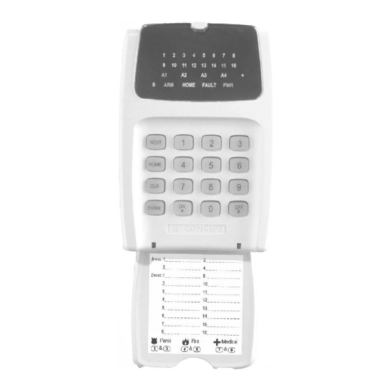
Page 6: The Led Terminal (Operator Terminal)
Version 2.02 December-2002 2. The LED Terminal 2.1 SPECIAL KEY FUNCTIONS NEXT -Select a Master User operation (Enter PIN code, press <NEXT> then the Address number). HOME -Used to Arm the system, or an individual Area, in Home Mode. Master User: -Clear the data already entered if you have made a mistake. -
Page 7: Lamp Indications
Version 2.02 December-2002 2.3 LAMP INDICATIONS. Lamp FLASHING ZONE Lamps When the Zone When the Zone FAST: * 1 to 16 is Unsealed. is Sealed. When there has been an (If the "Zone Alarm or Tamper/Fault on the Zone. Activity" option has SLOW: * been enabled) When the Zone has been Isolated. -
Page 8: User Operations
Version 2.02 December-2002 3. User Operations 3.1 QUICK ARMING. (If enabled in your system) SINGLE AREA SYSTEM: Enter Area number; to Arm the system. Enter Area number; to Arm the system in Home Mode. MULTI-AREA SYSTEM: Enter Area number; to Arm the system. Enter Area number;... -
Page 9: Arming / Dis-Arming Individual Areas In A Multi-Area System
Version 2.02 December-2002 3.4 ARMING / DIS-ARMING INDIVIDUAL AREAS IN A MULTI-AREA SYSTEM. The LED keypad allows the User to Arm and Dis-arm individual Areas in a Multi-Area system. The Lamps A1 A2 A3 A4 show when each area is armed. The procedure for Arming an individual Area is the same for Multi-Area and Single-Area mode. -
Page 10: Next
Version 2.02 December-2002 3.7 ISOLATING (BYPASSING): ZONE INPUTS NEXT 21 SYSTEM INPUTS NEXT 22 Enter the Isolate mode. (NEXT 21 for Zone Inputs OR NEXT 22 for System Inputs) Enter PIN; ... , then The <ARM> and <HOME> Lamps will flash together. The Zone Lamps will indicate the Inputs that are Isolated. -
Page 11: Pin Code Duress Alarm Activation
Version 2.02 December-2002 3.9 PIN CODE DURESS ALARM ACTIVATION. If enabled in your system, this function allows the User to activate the PIN Code Duress alarm while performing any normal LED Terminal operations. When activated, the system sends a silent Duress report to the Central Monitoring Station. No local indication is provided. -
Page 12: Next 13
Version 2.02 December-2002 3.12 VIEW ALARM HISTORY. NEXT 12 1. Enter the View Alarm History Mode. Press Any Zone Inputs that had an alarm during the last Armed period will be displayed on the Zone Lamps. Press to exit. 3.13 VIEW FAULT HISTORY. NEXT 13 1. -
Page 13: Next 15
Occasionally, the Installer may ask you to check the Version of the Firmware installed in your Concept IQ Controller. e.g. If you have asked the Installer to enable additional features or functions in your system and the Installer is not on-site. -
Page 14: Accessing The Operational Modes
Version 2.02 December-2002 Master User Operations 4.0 ACCESSING THE OPERATIONAL MODES. The Default Master Code is 0123. (Or 012345 if system is configured for 6 Digit PIN codes) This Code should be changed as soon as possible after installation. When choosing a new Master Code, ensure that a PIN code is chosen that will not be forgotten, while still providing security against unauthorised access. -
Page 15: Adding Or Changing Users
Version 2.02 December-2002 4.1 ADDING OR CHANGING USERS. NEXT 4xx 1. Logon. Enter your PIN code; 2. Select the first User number to be added or changed. Press Where is the User number (User 02 to User 47). The <A1> Lamp will flash to indicate the system is ready for the PIN Code or optional Wireless Remote Key/Access Card entry. - Page 16 Version 2.02 December-2002 Press the Area number for each Area that is to be Assigned or Un-assigned to this User. . OPTIONS: 0 All Areas De-selected. 1 General Area (Single Area Mode) or Area 1 (Multi-Area Mode) selected. 2 Area 2 selected 3 Area 3 selected 4 Area 4 selected When the required Areas have been Selected and/or De-selected, press...
-
Page 17: Deleting Users
Version 2.02 December-2002 4.2 DELETING A USER. NEXT 4xx 1. Logon. Enter your PIN code; 2. Select the first User number to be Deleted. Press Where is the User number (User 02 to User 47). The <A1> Lamp will flash to indicate the system is ready for the PIN Code or Wireless Remote Key/ Access Card entry. -
Page 18: Zone Walk Test Mode
Version 2.02 December-2002 4.3 ZONE WALK TEST. NEXT 23 1. Enter the Zone Alarm Walk Test Mode. Enter your PIN code; ... , then press In Alarm Test Mode, any Zone Input in the Terminal’s Associated Area that goes into the Alarm (Un- sealed) state will cause: - The corresponding Zone Lamp to fast flash. -
Page 19: Next 26
Version 2.02 December-2002 4.5 TEST TRANSMISSION. NEXT 25 This operation will instruct the Control Module to send a test transmission to a central station or a domestic telephone number. Enter your PIN code; ... , then press When transmitting to a Central Station in Contact ID format, Event Code 602 is sent. 4.6 BATTERY TEST. - Page 20 Version 2.02 December-2002 4.8 PROGRAM OR VIEW THE TELEPHONE NUMBERS. NEXT 31 1. Enter the Telephone Number programming Mode. Enter your PIN code; ... , then press The <A1> Lamp will flash to indicate the system is ready for the Primary Telephone Number entry. 2.
- Page 21 Version 2.02 December-2002 4. View the Secondary Telephone number. (If programmed) When the Primary Telephone Number has been keyed in and the <ENTER> key is pressed, the system will automatically advance to the Secondary Telephone Number. The <A2> Lamp will flash to indicate the system is ready for the Secondary Telephone Number entry. If a Secondary Telephone Number is already programmed, the digits of the current number will be displayed sequentially via the Zone Lamps and the “0”...
-
Page 22: Next 32
4.9 PROGRAM OR VIEW THE CALL DIVERT NUMBERS. NEXT 32 The Call Divert option enables the Concept IQ system to dial your Call Divert number when the system is fully Armed and dial your Call Un-divert number when the system is Disarmed. - Page 23 Version 2.02 December-2002 4. View the Call Un-Divert Telephone number. (If programmed) When the Call Divert Telephone Number has been keyed in and the <ENTER> key is pressed, the system will automatically advance to the Call Un-Divert Telephone Number. The <A2> Lamp will flash to indicate the system is ready for the Call Un-Divert Telephone Number entry. If a Call Un-Divert Telephone Number is already programmed, the digits of the current number will be displayed sequentially via the Zone Lamps and the “0”...
-
Page 24: Next 33
Version 2.02 December-2002 4.10 VIEW OR SET THE TIME AND DATE. NEXT 33 IMPORTANT NOTES: System Reset. In the event that power is completely removed from the System (i.e. Both the AC input and the Battery are disconnected), when power is restored, the Real-Time Clock will need to be re- programmed to the current Time and Date. - Page 25 Version 2.02 December-2002 3. Enter the current Time. The <A1> Lamp will flash to indicate the system is ready for the Time entry. Enter the Time data: (4 digits), then The time is stored in the following order: hh : mm i.e.
-
Page 26: Next
Version 2.02 December-2002 5. Telephone Remote Control Consult your installer to ascertain whether your system has the optional Telephone Remote Control enabled. (Telephone Remote Control requires the DTMF Card to be fitted to the Control Module) TELEPHONE KEY FUNCTIONS: The following Telephone Keys are used to perform the specified LED Terminal functions: IMPORTANT NOTE: Use short key presses. - Page 27 Version 2.02 December-2002 4.2) To Control an Auxiliary Output: Select Auxiliary Control Mode: Press <9>, then 24 (Auxiliary Control & Test Mode) Toggle the Auxiliary On or Off: Press <Auxiliary Number>, <#> e.g. To Turn Auxiliary 3 On. Press: 3, <#>. Logout of Aux Control Mode: Press <*>.
-
Page 28: Wireless Remote Control
Your system may be equipped with up to six 4-Button, RF Wireless Remote Control KeyFobs. (Wireless Remote Control is an optional feature and requires an Inner Range RF Receiver and an Enhanced RF LED Terminal or RF Module to be connected to the system) - Page 29 Version 2.02 December-2002 OPERATOR FEEDBACK FOR WIRELESS REMOTE KEY OPERATIONS: Your system may be programmed to provide audible and/or visual indication of Arm and Disarm operations perfomed from a Wireless Remote Key. Consult with your Installer regarding your requirements. The feedback options available are: Bell Squawk: One 200milliSecond squawk in each 1 Second period.
-
Page 30: Domestic Dialer Reporting
Version 2.02 December-2002 7. Domestic Dialer reporting Domestic Dialer reporting enables Area Open/Close and Alarm reports to be sent to a normal Telephone or Mobile Phone. Consult your installer to ascertain whether your system has Domestic dialing enabled, and whether a DTMF Card is fitted on your system. IMPORTANT NOTE: If the system is programmed to report to a Central Monitoring Station, your Installer must enable the “Dual Reporting”... -
Page 31: System Inputs Table
Version 2.02 December-2002 8. System Inputs Table The Table below shows: 1) The Input Number that each System Input is mapped to for reporting to a Central Monitoring Station. 2) The Zone Lamp that each System Input is mapped to when viewing the “Fault History” (NEXT 13) Zone Lamp Flashing = Currently in Alarm. - Page 32 2. This manual describes many optional features that may or may not be utilized in a particular system. Optional features generally require additional programming and/or installation of additional hardware. Consult the Installer for details of features and functions available in your system. © 2001-2002. Inner Range Pty. Ltd. Part Number: 630046...
Need help?
Do you have a question about the CONCEPT IQ and is the answer not in the manual?
Questions and answers