Inner Range Concept 4000 User Manual
Security, access control & building automation system hardware
Hide thumbs
Also See for Concept 4000:
- User manual (24 pages) ,
- Operation manual (8 pages) ,
- Installation manual (20 pages)
Table of Contents
Advertisement
Quick Links
Advertisement
Table of Contents

Related Manuals for Inner Range Concept 4000


Summary of Contents for Inner Range Concept 4000
-
Page 2: System Details
SYSTEM DETAILS CUSTOMER: ..................SITE ADDRESS / LOCATION: ................................PHONE: ........FAX: ......INSTALLED BY: ....................................PHONE: ........FAX: ......MAINTENANCE & SERVICE: ................................PHONE: ........FAX: ......MONITORED BY: ....................................PHONE: ........FAX: ......CARD TYPE USED: Credit Card Site Code Direct Entry... - Page 3 Installer for details of features and functions available in your system and use the check-boxes provided in the Table of Contents to indicate which are used. INNER RANGE recommends that all CONCEPT systems are installed & maintained by FACTORY CERTIFIED TECHNICIANS.
-
Page 4: Table Of Contents
CONCEPT 4000. CONCEPT 4000. CONCEPT 4000. CONCEPT 4000. CONCEPT 4000. User Manual. CONTENTS SYSTEM DETAILS ..........Inside Front Cover. MENU FLOWCHART ........Inside Rear Cover. SYSTEM OVERVIEW ............... 4 THE LCD TERMINAL ..............8 Default LCD Display / Indicator Lamps..........8, 9 The Keypad. -
Page 5: Table Of Contents
OTHER CONTROL PRODUCTS AND OPERATIONS Wireless RF Remote Fob Operations ..........108 Telephone (DTMF) Remote Control..........112 GSM Mobile phone Remote Control and Alarm messages ..... 114 Weatherproof Terminal Operations ..........120 INDEX ....................122 Concept 4000 User Interface Options..........125... -
Page 6: System Overview
CONCEPT 4000. CONCEPT 4000. CONCEPT 4000. CONCEPT 4000. CONCEPT 4000. User Manual. SYSTEM OVERVIEW The “3000” & “Access 4000” provide the next generation in Access Control, Security Management and Building Automation Systems. Both systems offer the system designer the ability to provide Security monitoring, Access Control and Automation as either independent or integrated facilities. -
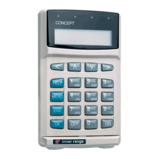
Page 7: The Lcd Terminal
CONCEPT 4000. CONCEPT 4000. CONCEPT 4000. CONCEPT 4000. CONCEPT 4000. User Manual. USERS Your system can be operated by one or more persons called “Users”. A User must have a PIN Code and/or a Card &/or a Wireless Remote in order to perform any operations. - Page 8 <HELP> key. WEATHERPROOF TERMINALS The Inner Range Weatherproof Terminal may be used to turn an Area ON and OFF &/or unlock a Door. This unit has a keypad with digit keys (0-9), OK key, ON/OFF key and a beeper.
- Page 9 CONCEPT 4000. CONCEPT 4000. CONCEPT 4000. CONCEPT 4000. CONCEPT 4000. User Manual. DOORS When Access Control is used in your system, each access point (Door, Roller Shutter, Turnstile, Boom gate, etc.) is called a “Door”. Installer programming options can provide for different types of Doors to be controlled and monitored in different ways.
- Page 10 CONCEPT 4000. CONCEPT 4000. CONCEPT 4000. CONCEPT 4000. CONCEPT 4000. User Manual. THE LCD TERMINAL Default LCD Display. The LCD Terminal offers a number of options for the Default display. This is the display that will be shown when there are no User operations being performed, and no Alarms or other messages to be displayed.
- Page 11 CONCEPT 4000. CONCEPT 4000. CONCEPT 4000. CONCEPT 4000. CONCEPT 4000. User Manual. TIME & DATE. (V5 or later only) The Time and Date option allows the current system Time and Date to be displayed. ...
-
Page 12: The Keypad
CONCEPT 4000. CONCEPT 4000. CONCEPT 4000. CONCEPT 4000. CONCEPT 4000. User Manual. The Keypad. Operations & programming are performed by using the keypad on an LCD Terminal. Each time a key is pressed, a short “beep” will be emitted to indicate that the key press was accepted. - Page 13 CONCEPT 4000. CONCEPT 4000. CONCEPT 4000. CONCEPT 4000. CONCEPT 4000. User Manual. The <OK> key must always be pressed after you have entered your secret PIN code (Unless performing a “Quick Arm or Disarm” operation). You have 10 seconds to press the <OK>...
-
Page 14: The Prisma Colour Graphic Terminal
The settings can only be programmed by the Installer, who can also advise you on the appropriate options. If no specific Default Display option has been chosen, the Concept 4000 logo will be displayed. SINGLE AREA STATUS. This option allows the name and current status of a single Area to be displayed. - Page 15 CONCEPT 4000. CONCEPT 4000. CONCEPT 4000. CONCEPT 4000. CONCEPT 4000. User Manual. Monday, 18th Apr 11:25am CUSTOM MESSAGE. The “Diaries” feature can be utilized to provide a Library customized message that is appropriate for the is Off particular Site and/or the particular Terminal.
-
Page 16: Level Messages
CONCEPT 4000. CONCEPT 4000. CONCEPT 4000. CONCEPT 4000. CONCEPT 4000. User Manual. USER OPERATIONS User operations are the basic day-to-day operations performed on the system. These include: Turning Areas ON and OFF. (Arming and Disarming) Walk Testing Zones. (If enabled for higher security) Acknowledging Alarm messages. -
Page 17: Logon To An Lcd Terminal
CONCEPT 4000. CONCEPT 4000. CONCEPT 4000. CONCEPT 4000. CONCEPT 4000. User Manual. LOGON to an LCD Terminal. Logging on is the first step performed in MOST operations. Enter your secret PIN Code using the digit keys, then press the <OK> key. Each digit pressed will be displayed as a hash (#) character. -
Page 18: Turning Area/S Off
CONCEPT 4000. CONCEPT 4000. CONCEPT 4000. CONCEPT 4000. CONCEPT 4000. User Manual. Turning Area/s OFF. Once you have Logged on to a Terminal, and have seen the Area status with the “Push Off” or “Push On” message, you may perform the Area OFF or ON operations. - Page 19 CONCEPT 4000. CONCEPT 4000. CONCEPT 4000. CONCEPT 4000. CONCEPT 4000. User Manual. -AREA / AREA LIST SELECTION. You may select other Areas or Area Lists by using the <UP> and <DOWN> Arrow keys and/or the <DIGIT> keys to select the 1st letter that the Area name begins with.
-
Page 20: Turning Area/S On
CONCEPT 4000. CONCEPT 4000. CONCEPT 4000. CONCEPT 4000. CONCEPT 4000. User Manual. Turning Area/s ON. IMPORTANT NOTE: Some systems in high security applications may have the Pre- Arm “Walk Test” feature enabled. (V3 or later only). In most systems this feature is not enabled and the Area ON procedure will simply be performed as described below. -
Page 21: Area Walk Testing
CONCEPT 4000. CONCEPT 4000. CONCEPT 4000. CONCEPT 4000. CONCEPT 4000. User Manual. After pressing the <ON> key, the display may show a message like this. It means that the item displayed ... - Page 22 CONCEPT 4000. CONCEPT 4000. CONCEPT 4000. CONCEPT 4000. CONCEPT 4000. User Manual. If the maximum time allowed for Walk Testing is about to expire, the normal display will alternate with ...
-
Page 23: Turning 24 Hour (Tamper) Monitoring Off And On
CONCEPT 4000. CONCEPT 4000. CONCEPT 4000. CONCEPT 4000. CONCEPT 4000. User Manual. Turning 24 Hour (Tamper) monitoring OFF and ON. The 24Hr part of an Area continuously monitors the equipment and inputs for faults or deliberate interference and activates “Tamper” alarms when these conditions occur. - Page 24 CONCEPT 4000. CONCEPT 4000. CONCEPT 4000. CONCEPT 4000. CONCEPT 4000. User Manual. Activating a “Panic” Alarm. Your system may be programmed to allow a Panic alarm to be easily activated from any LCD Terminal without needing to Log on. A Panic Alarm is activated by simply pressing the <HELP> key three times in a row.
- Page 25 CONCEPT 4000. CONCEPT 4000. CONCEPT 4000. CONCEPT 4000. CONCEPT 4000. User Manual. Activating a “Duress” Alarm. Your system may be programmed to allow a Duress alarm to be activated if you are being forced to perform operations at an LCD Terminal against your will.
-
Page 26: Acknowledge An Alarm
CONCEPT 4000. CONCEPT 4000. CONCEPT 4000. CONCEPT 4000. CONCEPT 4000. User Manual. Acknowledge an Alarm. Alarm messages must be acknowledged by a User with the appropriate authority. These messages provide precise information of the type of alarm, the Area it has occurred in, and the Zone or System Input that generated the alarm. - Page 27 CONCEPT 4000. CONCEPT 4000. CONCEPT 4000. CONCEPT 4000. CONCEPT 4000. User Manual. Acknowledge (Reset) Latched Alarms. If this message is displayed certain types of alarms in your system have been programmed to Latch. ...
-
Page 28: Access (Unlock) A Door
CONCEPT 4000. CONCEPT 4000. CONCEPT 4000. CONCEPT 4000. CONCEPT 4000. User Manual. Access (Unlock) a Door. Using an Access Reader. In Access Control systems Doors are commonly Un-locked using Card Readers. The Card, Keyfob or Insert key (etc) is simply swiped/presented to the Reader in the required manner. - Page 29 CONCEPT 4000. CONCEPT 4000. CONCEPT 4000. CONCEPT 4000. CONCEPT 4000. User Manual. Access a Floor in an Elevator. Using a Card Reader. In Lift Access Control systems, Floors are commonly accessed using Card Readers in conjunction with the Floor Selection buttons with the following procedure: In most cases the Card, Key fob or Insert key (etc) is simply swiped or presented to the Reader inside the Lift Car, in the required manner.
-
Page 30: View Alarm Review Information
CONCEPT 4000. CONCEPT 4000. CONCEPT 4000. CONCEPT 4000. CONCEPT 4000. User Manual. View Alarm Review information. Individual LCD Terminals may be programmed to allow Users to review recent Alarm information without needing to Log on to the Terminal. (V3 or later only) If this option is enabled, simply press the <MENU>... - Page 31 CONCEPT 4000. CONCEPT 4000. CONCEPT 4000. CONCEPT 4000. CONCEPT 4000. User Manual. View the Time and Date. This function allows Users to view the current system Time and Date without needing to Log on to the Terminal. (V4.5 or later only) Press the <MENU>...
-
Page 32: View Area Status
CONCEPT 4000. CONCEPT 4000. CONCEPT 4000. CONCEPT 4000. CONCEPT 4000. User Manual. View Area Status. Individual LCD Terminals may be programmed to allow Users to view the current status of Areas without needing to Log on to the Terminal. (V3 or later only) If this option is enabled, simply press the <UP>... -
Page 33: Home Auxiliary Control
CONCEPT 4000. CONCEPT 4000. CONCEPT 4000. CONCEPT 4000. CONCEPT 4000. User Manual. Home Auxiliary Control. Individual LCD Terminals may be programmed to allow Users to control specified Home Auxiliaries without needing to Log on to the Terminal. Home Auxiliaries are outputs that can be controlled by a User at an LCD Terminal and/ or controlled automatically by the system. - Page 34 CONCEPT 4000. CONCEPT 4000. CONCEPT 4000. CONCEPT 4000. CONCEPT 4000. User Manual. Controlling the Home Auxiliary. When the desired Home Auxiliary is displayed; Press the ON key or OFF key to turn the Auxiliary On or Off as required.
-
Page 35: Air Conditioning Control
CONCEPT 4000. CONCEPT 4000. CONCEPT 4000. CONCEPT 4000. CONCEPT 4000. User Manual. Air Conditioning Control. Some sytems utilize special dedicated built-in logic in the Access 4000 for Air- conditioning system Control. This allows Air-conditioning sytems to be controlled by a User at an LCD Terminal and/or controlled automatically by the system. - Page 36 CONCEPT 4000. CONCEPT 4000. CONCEPT 4000. CONCEPT 4000. CONCEPT 4000. User Manual. Use the <RIGHT> arrow key to select the mode of operation required. Turn the Airconditioning On. Turn the Airconditioning Off. TimeZone Airconditioning system will be automatically turned On and Off by the TimeZone assigned to it by the installer.
-
Page 37: Menu Options
CONCEPT 4000. CONCEPT 4000. CONCEPT 4000. CONCEPT 4000. CONCEPT 4000. User Manual. MENU OPTIONS Users with the appropriate level of authority can perform many other operations and are allowed access to certain programming facilities via the Menu. A Menu Flowchart showing all the Options can be found inside the back cover. -
Page 38: Keypad Functions In The Menu
CONCEPT 4000. CONCEPT 4000. CONCEPT 4000. CONCEPT 4000. CONCEPT 4000. User Manual. Keypad Functions in the Menu. The functions of the 20 keys while performing control, programming or viewing operations in the menu are described below. Scrolls up and down a list of available items to view, program or control. - Page 39 CONCEPT 4000. CONCEPT 4000. CONCEPT 4000. CONCEPT 4000. CONCEPT 4000. User Manual. Information: Menu Option 1 ACCESSING REVIEW. Allows a User to view the list of review events stored REVIEW in the memory. This may be necessary to find out details of past alarms or user activity, etc.
- Page 40 CONCEPT 4000. CONCEPT 4000. CONCEPT 4000. CONCEPT 4000. CONCEPT 4000. User Manual. REVIEW FILTER: The DIGIT keys, 1 to 8 can be used to search back through review for specific types of events, beginning from the date/time of the event currently displayed.
- Page 41 CONCEPT 4000. CONCEPT 4000. CONCEPT 4000. CONCEPT 4000. CONCEPT 4000. User Manual. LOCATE USER In some systems INSIDE and/or OUTSIDE Areas will have been assigned to Access Controlled Doors. “LOCATE USER” can then be used to display the Area that the user is currently in.
- Page 42 CONCEPT 4000. CONCEPT 4000. CONCEPT 4000. CONCEPT 4000. CONCEPT 4000. User Manual. READ ANALOGUE VALUES In some systems Analogue Input modules are installed to monitor variable parameters such as Temperature, humidity, fluid levels, etc. “READ ANALOGUE” can then be used to display the current values of the analogue inputs.
- Page 43 CONCEPT 4000. CONCEPT 4000. CONCEPT 4000. CONCEPT 4000. CONCEPT 4000. User Manual. READ COUNTERS In some systems Mini Expander modules are installed to perform Event Counting. Event Counters can be used to monitor film in security cameras, water or electricity usage, traffic through a designated point, etc.
- Page 44 CONCEPT 4000. CONCEPT 4000. CONCEPT 4000. CONCEPT 4000. CONCEPT 4000. User Manual. VIEW INPUT STATES The system can be programmed to allow Users to view a summary of specific Zones that are enabled and currently in an abnormal condition. “INPUT STATES” can then be used to display the IMPORTANT NOTE: This summary.
- Page 45 CONCEPT 4000. CONCEPT 4000. CONCEPT 4000. CONCEPT 4000. CONCEPT 4000. User Manual. CLEAR TROUBLE ZONES The system can be programmed to allow appropriate Users to clear “Trouble Zones” that are preventing one or more Areas from being turned On. i.e. Zones that have had an alarm, or...
- Page 46 CONCEPT 4000. CONCEPT 4000. CONCEPT 4000. CONCEPT 4000. CONCEPT 4000. User Manual. READ POWER MODULE VALUES In some systems LAN Power Supply Modules are installed to provide flexible, general purpose, battery-backed power supply solutions with the added advantage of immediate status reporting of Power Supply conditions and problems via the LAN network.
- Page 47 CONCEPT 4000. CONCEPT 4000. CONCEPT 4000. CONCEPT 4000. CONCEPT 4000. User Manual. Use the <UP> and <DOWN> Arrow keys to scroll through the results for the same parameter on other Power Modules. Press <OK> to advance, in turn, to each of the other Power Module Parameters to be viewed on the same Power Module.
- Page 48 CONCEPT 4000. CONCEPT 4000. CONCEPT 4000. CONCEPT 4000. CONCEPT 4000. User Manual. Access Menu: Menu Option 2 USER PROGRAMMING User programming allows details to be defined for each individual User. i.e. Name, PIN code and/or Card details, expiry date/time, operations and items allowed (by allocating a “User Type”), etc.
- Page 49 CONCEPT 4000. CONCEPT 4000. CONCEPT 4000. CONCEPT 4000. CONCEPT 4000. User Manual. User Programming Flowchart s i h > > . d i i t p ) l a o i t o i t r e t > >...
- Page 50 CONCEPT 4000. CONCEPT 4000. CONCEPT 4000. CONCEPT 4000. CONCEPT 4000. User Manual. SELECT “USER CODES”. SELECT A USER TO PROGRAM/EDIT. The display will first allow you to choose a User ...
- Page 51 CONCEPT 4000. CONCEPT 4000. CONCEPT 4000. CONCEPT 4000. CONCEPT 4000. User Manual. “RUTH” would be programmed with the sequence EXAMPLE: shown opposite. • Pressing a key more than once will scroll through all the characters associated with that key until the one you require is displayed.
- Page 52 Site Code magnetic stripe formats. recorded in the “System ii) Site Code. For Wiegand formats utilizing a Details” inside the Front cover. Site Code, or Inner Range magnetic stripe If not recorded, consult the cards with Site Code format. Installer for details.
- Page 53 CONCEPT 4000. CONCEPT 4000. CONCEPT 4000. CONCEPT 4000. CONCEPT 4000. User Manual. i) CREDIT CARD - ACCOUNT NUMBER The “Account number” for Credit Cards is programmed by entering the account number OR ...
- Page 54 CONCEPT 4000. CONCEPT 4000. CONCEPT 4000. CONCEPT 4000. CONCEPT 4000. User Manual. ii) SITE CODE - CARD NUMBER The “Card number” for Site Code Cards is defaulted to the User number. Typically, when using “Site ...
- Page 55 CONCEPT 4000. CONCEPT 4000. CONCEPT 4000. CONCEPT 4000. CONCEPT 4000. User Manual. When complete: <OK> key to move on to the next question for this User. <UP> key to edit the previous User’s “Issue No”. <DOWN> key to edit the next User’s “Issue No”.
- Page 56 CONCEPT 4000. CONCEPT 4000. CONCEPT 4000. CONCEPT 4000. CONCEPT 4000. User Manual. EXPIRY DATE AND TIME Depending on your system configuration, you may be able to program when a User Code/Card ...
- Page 57 CONCEPT 4000. CONCEPT 4000. CONCEPT 4000. CONCEPT 4000. CONCEPT 4000. User Manual. USER TENANCY (V6.2 or later only) Depending on your system configuration, the Installer or Master User may be able to program ...
- Page 58 CONCEPT 4000. CONCEPT 4000. CONCEPT 4000. CONCEPT 4000. CONCEPT 4000. User Manual. USER OPTIONS There are currently five special options which may be set for a User. Use the <RIGHT> Arrow, followed by the <9>...
- Page 59 CONCEPT 4000. CONCEPT 4000. CONCEPT 4000. CONCEPT 4000. CONCEPT 4000. User Manual. EXTRA AREA The Area/s that Users can control are normally only defined by the Area ON List and Area OFF List allocated to their “User Type”. The “Extra Area” option allows one Area to be ...
- Page 60 CONCEPT 4000. CONCEPT 4000. CONCEPT 4000. CONCEPT 4000. CONCEPT 4000. User Manual. EXTRA DOOR & EXTRA DOOR LIST The Door/s that Users may access are normally only defined by the Door List allocated to their “User Type”. The “Extra Door”/“Extra Door List” options allow ...
- Page 61 CONCEPT 4000. CONCEPT 4000. CONCEPT 4000. CONCEPT 4000. CONCEPT 4000. User Manual. RF FOB OPTIONS If a Wireless Remote Fob has been registered to this User, these options may be used to program the operation of the button/s available on the Fob.
- Page 62 CONCEPT 4000. CONCEPT 4000. CONCEPT 4000. CONCEPT 4000. CONCEPT 4000. User Manual. The table below shows which User RF Fob programming options apply to the actual buttons on the range of different RF Fob devices supported. User RF Fob programming options.
- Page 63 CONCEPT 4000. CONCEPT 4000. CONCEPT 4000. CONCEPT 4000. CONCEPT 4000. User Manual. The list of available actions is shown in the following table. NOTES: 1. For Paradox Remotes, the ARM1 or ARM2 programming options should be used to configure Area On/Off operations, rather than the “Btn1”...
- Page 64 CONCEPT 4000. CONCEPT 4000. CONCEPT 4000. CONCEPT 4000. CONCEPT 4000. User Manual. When complete: <OK> key to move on to the programming of the operations for Fob Buttons 2, 3 & 4, and then on to the Paradox REM1/2/3 programming options (or next User to program/ edit if prior to V7.62).
- Page 65 CONCEPT 4000. CONCEPT 4000. CONCEPT 4000. CONCEPT 4000. CONCEPT 4000. User Manual. The ARM2 options allow the ARM/OFF 2 buttons on the REM3 Fob to be programmed.
- Page 66 CONCEPT 4000. CONCEPT 4000. CONCEPT 4000. CONCEPT 4000. CONCEPT 4000. User Manual. EXIT USER CODE PROGRAMMING When you have completed your programming session, use the <END> key to exit the menu. This can be done at any point in the procedure.
- Page 67 CONCEPT 4000. CONCEPT 4000. CONCEPT 4000. CONCEPT 4000. CONCEPT 4000. User Manual. DELETING A USER Deleting or temporarily suspending a User is a simple process. Select a User to Edit by User number or by Name, ...
- Page 68 CONCEPT 4000. CONCEPT 4000. CONCEPT 4000. CONCEPT 4000. CONCEPT 4000. User Manual. USER TYPES Some Users, such as System Administrators, may be allowed to program “User Types”. User Types are assigned to Users to define the items they are allowed to control, the functions they can perform and the Menu options that they can access.
- Page 69 CONCEPT 4000. CONCEPT 4000. CONCEPT 4000. CONCEPT 4000. CONCEPT 4000. User Manual. ASSIGN A TIMEZONE. The display will show the current TimeZone name. If a TimeZone is assigned, the User Type will only ...
- Page 70 CONCEPT 4000. CONCEPT 4000. CONCEPT 4000. CONCEPT 4000. CONCEPT 4000. User Manual. Menu Group is assigned to define which Operations and Menu options this User Type is allowed to access ...
- Page 71 CONCEPT 4000. CONCEPT 4000. CONCEPT 4000. CONCEPT 4000. CONCEPT 4000. User Manual. [d]isabled User. Provides longer Door Un-lock time and longer (V3 or later only) Lift button selection time for this User Type. The Door Un-lock time will be 4 times the period programmed by the installer for each Door.
- Page 72 CONCEPT 4000. CONCEPT 4000. CONCEPT 4000. CONCEPT 4000. CONCEPT 4000. User Manual. USER TYPE TENANCY (V6.2 or later only) The display shows the current Tenancy allocated. If a User has the ability to Program/Edit Users, ...
- Page 73 CONCEPT 4000. CONCEPT 4000. CONCEPT 4000. CONCEPT 4000. CONCEPT 4000. User Manual. LISTS THEN: - DOOR FLOOR LIFT CAR Lists Lists List Some Users, such as System Administrators, may be allowed to program one or more of the different types of “Lists”. Lists are used in other programming options such as “User Types”...
- Page 74 CONCEPT 4000. CONCEPT 4000. CONCEPT 4000. CONCEPT 4000. CONCEPT 4000. User Manual. LIST NAME. The display will show the number and current name. (Name not available on some Lists) To enter a new name, press the <OFF> key to - - - clear the screen, then use the <DIGIT>...
- Page 75 CONCEPT 4000. CONCEPT 4000. CONCEPT 4000. CONCEPT 4000. CONCEPT 4000. User Manual. ALTERNATE LIST. The display will show the current Alternate List. If an Alternate List is assigned it will be used ...
- Page 76 CONCEPT 4000. CONCEPT 4000. CONCEPT 4000. CONCEPT 4000. CONCEPT 4000. User Manual. MENU GROUPS Some Users, such as System Administrators, may be allowed to program “Menu Groups”. Menu Groups are assigned to User Types to define what actions, functions and menu options the User Type is allowed to perform or access when logged on to an LCD Terminal.
- Page 77 CONCEPT 4000. CONCEPT 4000. CONCEPT 4000. CONCEPT 4000. CONCEPT 4000. User Manual. MENU GROUP NAME. The display will show the number and current name. A name of up to 16 characters can be programmed - - - in the same manner as described for User names.
- Page 78 CONCEPT 4000. CONCEPT 4000. CONCEPT 4000. CONCEPT 4000. CONCEPT 4000. User Manual. MENU GROUP OPTIONS There are eight functional options which may be set for a Menu Group. Use the <RIGHT> Arrow, followed by the <9>...
- Page 79 CONCEPT 4000. CONCEPT 4000. CONCEPT 4000. CONCEPT 4000. CONCEPT 4000. User Manual. ASSIGN MAIN MENU OPTIONS This display is used to define the Main Menu options that the Menu Group will allow access to. ...
- Page 80 CONCEPT 4000. CONCEPT 4000. CONCEPT 4000. CONCEPT 4000. CONCEPT 4000. User Manual. ASSIGN SUB MENU OPTIONS This display is used to define the Sub Menu options that the Menu Group will allow access to. ...
- Page 81 CONCEPT 4000. CONCEPT 4000. CONCEPT 4000. CONCEPT 4000. CONCEPT 4000. User Manual. [O]wn Area List only. To simplify Area List selection if arming/disarming via Area Lists, the User will only be presented with their User Type’s Area On List. (V4 or later only) Un[L]ock ON key.
- Page 82 CONCEPT 4000. CONCEPT 4000. CONCEPT 4000. CONCEPT 4000. CONCEPT 4000. User Manual. RF FOB REGISTRATION This Menu option allows a Wireless RF Remote Fob to be Registered to a User, and a User’s Fob Registration status to be viewed. ...
- Page 83 CONCEPT 4000. CONCEPT 4000. CONCEPT 4000. CONCEPT 4000. CONCEPT 4000. User Manual. 3) If the transmission is from a Fob that is not registered, and the displayed User does not have a ...
-
Page 84: Isolate: Menu Option 3
CONCEPT 4000. CONCEPT 4000. CONCEPT 4000. CONCEPT 4000. CONCEPT 4000. User Manual. Isolate: Menu Option 3 If a detector or alarm contact is faulty, or their cabling has been shorted or cut, you may be unable to turn ON any Area that the faulty device is in. - Page 85 CONCEPT 4000. CONCEPT 4000. CONCEPT 4000. CONCEPT 4000. CONCEPT 4000. User Manual. HomeZone selection. The display will show the name and current status of the first HomeZone. (V3 or later only) ...
- Page 86 CONCEPT 4000. CONCEPT 4000. CONCEPT 4000. CONCEPT 4000. CONCEPT 4000. User Manual. Testing: Menu Option 4 Your system may be programmed with an option to allow Walk testing of specified Zones in particular Areas. (V3 or later only) Testing simply involves activating the devices (usually detectors) and then allowing them to return to their normal state.
- Page 87 CONCEPT 4000. CONCEPT 4000. CONCEPT 4000. CONCEPT 4000. CONCEPT 4000. User Manual. After an initial test to check that all Zones are Sealed, the Walk Test commences. The display will update ...
-
Page 88: Times: Menu Option 5
CONCEPT 4000. CONCEPT 4000. CONCEPT 4000. CONCEPT 4000. CONCEPT 4000. User Manual. Times: Menu Option 5 The time and date can be set and adjusted in the SET TIME AND DATE “Times” menu. This will be necessary when the system is first commissioned and for daylight saving changes. - Page 89 CONCEPT 4000. CONCEPT 4000. CONCEPT 4000. CONCEPT 4000. CONCEPT 4000. User Manual. Some Users, such as System Administrators, may TIMEZONES be allowed to program/edit “TimeZones”. TimeZones may be used to define when User access to specific functions and items (Areas, Doors, etc) is allowed;...
- Page 90 CONCEPT 4000. CONCEPT 4000. CONCEPT 4000. CONCEPT 4000. CONCEPT 4000. User Manual. TIMEZONE NAME. The display will show the number and current name. A name of up to 16 characters can be programmed in the same manner as described for User names.
- Page 91 CONCEPT 4000. CONCEPT 4000. CONCEPT 4000. CONCEPT 4000. CONCEPT 4000. User Manual. PROGRAM THE HOLIDAY TYPES. The display will show the current Holiday Types that will be obeyed by this Timezone. ...
- Page 92 CONCEPT 4000. CONCEPT 4000. CONCEPT 4000. CONCEPT 4000. CONCEPT 4000. User Manual. PROGRAM THE QUALIFY OPTIONS. The display will show the current Qualify option settings. The Qualify options allow the TimeZone ...
- Page 93 CONCEPT 4000. CONCEPT 4000. CONCEPT 4000. CONCEPT 4000. CONCEPT 4000. User Manual. Some Users, such as System Administrators, may HOLIDAYS be allowed to program “Holidays”. Holidays are used with TimeZones to define whether a TimeZone will be Invalid or Valid on dates designated as Holidays.
- Page 94 CONCEPT 4000. CONCEPT 4000. CONCEPT 4000. CONCEPT 4000. CONCEPT 4000. User Manual. HOLIDAY NAME. The display will show the number and current name. A name of up to 16 characters can be programmed in the same manner as described for User names.
- Page 95 CONCEPT 4000. CONCEPT 4000. CONCEPT 4000. CONCEPT 4000. CONCEPT 4000. User Manual. DIARIES Some Users, such as System Administrators, may be allowed to program “Diaries”. Diaries are mainly used to display customised messages on selected LCD Terminals at various selectable times.
- Page 96 CONCEPT 4000. CONCEPT 4000. CONCEPT 4000. CONCEPT 4000. CONCEPT 4000. User Manual. NOTE: To remove a Diary do not press <OFF>. This will make the Diary continuously valid. Instead, set the Date and Time to 00/00/88 - 00:00 <OK> key for next option. <UP> / <DOWN> to edit this option for the previous/next Diary.
- Page 97 CONCEPT 4000. CONCEPT 4000. CONCEPT 4000. CONCEPT 4000. CONCEPT 4000. User Manual. CAUTION: The following options should only be programmed by the Installer. ASSIGN A DIARY AUXILIARY. The display will show the current Auxiliary output assigned to the Diary. This Auxiliary will ...
- Page 98 CONCEPT 4000. CONCEPT 4000. CONCEPT 4000. CONCEPT 4000. CONCEPT 4000. User Manual. Miscellaneous Menu: Menu Option 6 This menu allows a User with the appropriate MODULE DISABLE level of authority to disable/enable a LAN Module. (V5.27 or later only) Disabling a Module causes the Module to stop ...
- Page 99 CONCEPT 4000. CONCEPT 4000. CONCEPT 4000. CONCEPT 4000. CONCEPT 4000. User Manual. The “UK Reset” option allows a User with the UK RESET appropriate authority to reset the “ON key lockout” condition after an alarm. IMPORTANT NOTE: This operation is only relevant to specific countries (e.g.
-
Page 100: Service: Menu Option 8
CONCEPT 4000. CONCEPT 4000. CONCEPT 4000. CONCEPT 4000. CONCEPT 4000. User Manual. Service: Menu Option 8 “REQUEST SERVICE” and “TEST REPORT”. IMPORTANT NOTES: 1) These options are only valid if the system is connected to a telephone line and the function has been enabled in the Installer programming options. - Page 101 CONCEPT 4000. CONCEPT 4000. CONCEPT 4000. CONCEPT 4000. CONCEPT 4000. User Manual. This menu option causes a message to be sent to TEST REPORT the Monitoring Station to Test the Reporting function. (Only available V3.0 or later) See “Important Notes” on the previous page.
- Page 102 CONCEPT 4000. CONCEPT 4000. CONCEPT 4000. CONCEPT 4000. CONCEPT 4000. User Manual. If remote access to the system is required for ANSWER PHONE service purposes via the dialer phone line, the service technician may ask you to activate the “Answer phone” function, in order to establish the communications connection.
-
Page 103: Control: Menu Option 9
CONCEPT 4000. CONCEPT 4000. CONCEPT 4000. CONCEPT 4000. CONCEPT 4000. User Manual. Control: Menu Option 9 HOME AUXILIARIES Home Auxiliaries are outputs in the system that can be turned On and Off by a User. Access to control of some Home Auxiliaries may be gained by simply pressing the <RIGHT>... - Page 104 CONCEPT 4000. CONCEPT 4000. CONCEPT 4000. CONCEPT 4000. CONCEPT 4000. User Manual. DOOR CONTROL The “Door Open/Close” option allows a User with the appropriate authority to Un-lock and Lock individual Doors (V3 or later only) or all Doors in NOTE: Only Doors included the Door List assigned to their User Type.
- Page 105 CONCEPT 4000. CONCEPT 4000. CONCEPT 4000. CONCEPT 4000. CONCEPT 4000. User Manual. LIFT CONTROL “Lift Access/Secure” allows a User with the appropriate authority to Access or Secure Floor/s in a specific Lift Car. If accessed, all Users may access the floors. If secured, only valid Users may access the floors.
- Page 106 CONCEPT 4000. CONCEPT 4000. CONCEPT 4000. CONCEPT 4000. CONCEPT 4000. User Manual. ADJUST EVENT COUNT Adjust Event Count allows a User with the appropriate authority to reset an Event Counter (to 0) or to set the count value to the required number.
- Page 107 CONCEPT 4000. CONCEPT 4000. CONCEPT 4000. CONCEPT 4000. CONCEPT 4000. User Manual. ADJUST AREA USER COUNT Adjust Area User Count allows a User with the appropriate authority to reset an Area User Counter (to 0) or to set the count value to the required number.
- Page 108 CONCEPT 4000. CONCEPT 4000. CONCEPT 4000. CONCEPT 4000. CONCEPT 4000. User Manual. ANTI-PASSBACK AMNESTY (ADJUST USER LOCATION) Systems utilizing Anti-passback processing may require a facility to allow a User, with the appropriate authority, to provide amnesty to one or more Users who are in violation of the Anti-passback rules.
- Page 109 CONCEPT 4000. CONCEPT 4000. CONCEPT 4000. CONCEPT 4000. CONCEPT 4000. User Manual. Edit the User location. The display will now show the User number on the top line and the ...
- Page 110 CONCEPT 4000. CONCEPT 4000. CONCEPT 4000. CONCEPT 4000. CONCEPT 4000. User Manual. Wireless Remote Fob Operations. Some sytems may utilize Wireless RF Remote Fobs to perform Area control, Auxiliary control, and Alarm functions. Any Fobs to be used in the system must first be enrolled by being registered to individual Users.
- Page 111 CONCEPT 4000. CONCEPT 4000. CONCEPT 4000. CONCEPT 4000. CONCEPT 4000. User Manual. When using RF Fobs, only 1 button may be pushed at a time and a pause of at least 2 seconds is required between subsequent button pushes. (This avoids repeated processing if the transmission is received by more than one RF Expander Module.)
- Page 112 CONCEPT 4000. CONCEPT 4000. CONCEPT 4000. CONCEPT 4000. CONCEPT 4000. User Manual. PARADOX FOB PGM BUTTON FUNCTIONS Users: ..............................Button. Function. REM1 REM2 REM3 PGM1 ..............PGM2 ..............PGM3 ..............PGM4 ..............Users: ..............................Button. Function. REM1 REM2 REM3 PGM1 ..............
- Page 113 CONCEPT 4000. CONCEPT 4000. CONCEPT 4000. CONCEPT 4000. CONCEPT 4000. User Manual. VISONIC FOB BUTTON FUNCTIONS Users: ......................................Button. Function............................................................................. Users: ......................................Button. Function............................................................................. Users: ......................................Button. Function....................
- Page 114 CONCEPT 4000. CONCEPT 4000. CONCEPT 4000. CONCEPT 4000. CONCEPT 4000. User Manual. Telephone Remote Control. Some sytems may utilize the “DTMF Control” option to allow the system to be controlled by any telephone able to send DTMF tones. i.e. Any touch tone phone. By dialing the system and using the telephone keypad, pre-defined Areas and Auxiliary outputs can be turned On and/or Off with different 4 digit codes.
- Page 115 CONCEPT 4000. CONCEPT 4000. CONCEPT 4000. CONCEPT 4000. CONCEPT 4000. User Manual. DTMF CONTROL DETAILS System Telephone No: ................“Control Mode” Tone: ......Control Codes: Action. ___ ___ ___ ___ ....................___ ___ ___ ___ ....................___ ___ ___ ___ ....................
- Page 116 CONCEPT 4000. CONCEPT 4000. CONCEPT 4000. CONCEPT 4000. CONCEPT 4000. User Manual. GSM Mobile phone Control and Alarm messages. An optional GSM modem can be installed with your system and programmed to allow communications via the GSM Digital Mobile network. (Only available V3.5 or later) The GSM modem may be used to provide the primary or backup alarm reporting to a Central Monitoring Station.
- Page 117 CONCEPT 4000. CONCEPT 4000. CONCEPT 4000. CONCEPT 4000. CONCEPT 4000. User Manual. SMS Alarm Text messages. Receiving the messages: The System will send the specified messages to the nominated GSM Mobile phone with a validity period of 168 hours (1 week). i.e. The message will be discarded by the network if not received by the nominated Mobile phone within 168 hours.
- Page 118 CONCEPT 4000. CONCEPT 4000. CONCEPT 4000. CONCEPT 4000. CONCEPT 4000. User Manual. Acknowledging SMS Alarm messages: IMPORTANT NOTES: Only required if SMS Alarm Text Message Acknowledgement has been enabled for your system. If unsure, check with the Installer. Open/Close messages also have an SMS Alarm ID, but do not need to be acknowledged.
- Page 119 CONCEPT 4000. CONCEPT 4000. CONCEPT 4000. CONCEPT 4000. CONCEPT 4000. User Manual. System Control via Short Message Service (SMS) The following information must be provided to the installer to enable the feature to operate as required: 1. The type/s of commands that will be allowed via the GSM Short Message Service.
- Page 120 CONCEPT 4000. CONCEPT 4000. CONCEPT 4000. CONCEPT 4000. CONCEPT 4000. User Manual. SMS TEXT COMMANDS. COMMAND SEQUENCE AND OPTIONS: s i l n i t l i a r a l r e t . g . e r i <...
- Page 121 CONCEPT 4000. CONCEPT 4000. CONCEPT 4000. CONCEPT 4000. CONCEPT 4000. User Manual. SMS CONFIRMATION & INFORMATION MESSAGES: r i f r t n < > e < > f < > e e < . > . g . i f f a i l i <...
-
Page 122: Weatherproof Terminal Operations
CONCEPT 4000. CONCEPT 4000. CONCEPT 4000. CONCEPT 4000. CONCEPT 4000. User Manual. Weatherproof Terminal Operations. INTRODUCTION The Weatherproof Terminal is supported in V5.6 or later and can currently provide the following operations: Access control on a single Door including the “auto area off” and “Request to Exit”... - Page 123 CONCEPT 4000. CONCEPT 4000. CONCEPT 4000. CONCEPT 4000. CONCEPT 4000. User Manual. OPERATION Logging On. All operations begin with entering your PIN code, followed by the <OK> key. (Beeper feedback is provided for each key press) If the PIN code is valid at this time, the CODE lamp will turn on and the User is considered “logged on”.
-
Page 124: Index
CONCEPT 4000. CONCEPT 4000. CONCEPT 4000. CONCEPT 4000. CONCEPT 4000. User Manual. INDEX Auxiliaries 7 1-button Wireless remote 59 Battery Problem 14 15-button Wireless remote 59 Battery Test 95 24 Hour (Tamper) monitoring 21 4-button Wireless remote 59 Cancel Holdup 76... - Page 125 CONCEPT 4000. CONCEPT 4000. CONCEPT 4000. CONCEPT 4000. CONCEPT 4000. User Manual. Fob User feedback 109 Master Code 46 GSM Mobile phone 114, 117 Menu Group 68, 74 GSM SMS 114 MENU GROUP OPTIONS 76 Menu Options 35, 77 Had Alarm 24...
- Page 126 Due to ongoing development and product improvements, the contents of this manual are subject to change without notice. Enquiries or comments relating to this manual should be sent to Don Sargent at Inner Range. E-MAIL: donald.sargent@innerrange.com FAX: +61 3 9753 3499.
-
Page 127: Concept 4000 User Interface Options
CONCEPT 4000. CONCEPT 4000. CONCEPT 4000. CONCEPT 4000. CONCEPT 4000. User Manual. Concept 4000 User Interface Options. Elite LCD Terminal See pages 6 & 8-11 for details. Colour Touchscreen Terminal See pages 1 & 6 for details. See next page for more options. - Page 128 CONCEPT 4000. CONCEPT 4000. CONCEPT 4000. CONCEPT 4000. CONCEPT 4000. User Manual. Concept 4000 User Interface Options. Prisma Colour Graphic Terminal See pages 1, 6 & 12-13 for details. Weatherproof Keypad See pages 6 & 120-121 for details. See previous page for more options.
Need help?
Do you have a question about the Concept 4000 and is the answer not in the manual?
Questions and answers