Inner Range concept iq User Manual
Hide thumbs
Also See for concept iq:
- User manual (32 pages) ,
- Installation and programming manual (74 pages)
Table of Contents
Advertisement
Quick Links
Advertisement
Table of Contents

Related Manuals for Inner Range concept iq


Summary of Contents for Inner Range concept iq
- Page 1 Version 1.03 January-2002 ’ ANUAL...
-
Page 2: System Details
Version 1.03 January-2002 System Details CUSTOMER: .............................................. PHONE: ........... FAX: ........... INSTALLED BY: .............................................. PHONE: ........... FAX: ........... MAINTENANCE & SERVICE: ......................................... PHONE: ........... FAX: ........... MONITORED BY: ............................................. PHONE: ........... FAX: ........... AREAS: 1 ............2 ..........3 ............ -
Page 3: Table Of Contents
Version 1.03 January-2002 Contents System Details ................2 Introduction System Overview ................4 Types of Users. Installer, Master & Normal Users..... 5 Default Users ................. 5 The LED Terminal (Operator Terminal) Special key functions..............6 Beeper indications................. 6 Lamp indications. -
Page 4: Introduction
Your CONCEPT IQ System. Thank you for purchasing this CONCEPT product. Your CONCEPT IQ System is part of a product family that has been protecting people and property, controlling personnel access and automating building functions in an enormous variety of premises and industrial sites for over 12 years. -
Page 5: Types Of Users. Installer, Master & Normal Users
Version 1.03 January-2002 1.2 TYPES OF USERS The system has 2 special Users and 45 normal Users. The system can be configured for 4 digit or 6 digit PIN codes depending on the requirements of the site. The normal Users can each be assigned a “User Type”... -
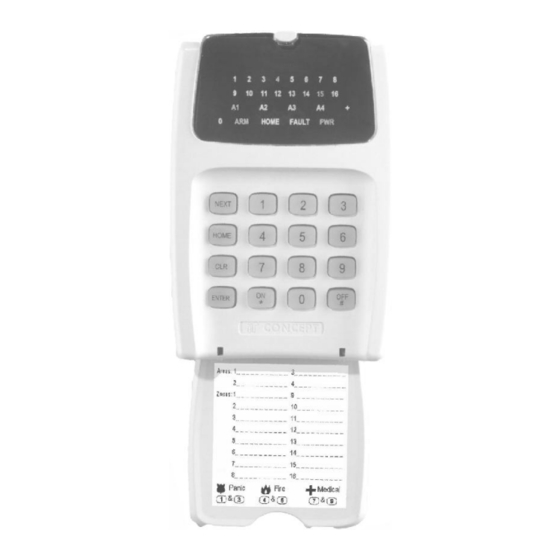
Page 6: The Led Terminal (Operator Terminal)
Version 1.03 January-2002 2. The LED Terminal 2.1 SPECIAL KEY FUNCTIONS NEXT -Select a Master User operation. (Enter PIN code, press <NEXT> then the Mode number. HOME -Used to Arm the system, or an individual Area, in Home Mode. Master User: -Used to step through programming Addresses (Users or Telephone numbers) -Used to toggle between Zone Test modes. -
Page 7: Lamp Indications
Version 1.03 January-2002 2.3 LAMP INDICATIONS. Lamp FLASHING ZONE Lamps When the Zone When the Zone FAST: * 1 to 16 is Un-sealed. is Sealed. When there has been an (If the "Zone Alarm / Tamper on the Zone. activity" option SLOW: * enabled) When the Zone has been Isolated. -
Page 8: User Operations
Version 1.03 January-2002 3. User Operations 3.1 QUICK ARMING. (If enabled in your system) SINGLE AREA SYSTEM: Enter Area number; to Arm the system. Enter Area number; to Arm the system in Home Mode. MULTI-AREA SYSTEM: Enter Area number; to Arm the system. Enter Area number;... -
Page 9: Arming / Dis-Arming Individual Areas In A Multi-Area System
Version 1.03 January-2002 3.4 ARMING / DIS-ARMING INDIVIDUAL AREAS IN A MULTI-AREA SYSTEM. The LED keypad allows the User to Arm and Dis-arm individual Areas in a Multi-Area system. The Lamps A1 A2 A3 A4 show when each area is armed. The procedure for Arming an individual Area is the same for Multi-Area and Single-Area mode. -
Page 10: Emergency Alarm Activation. -Panic, Fire And Medical Alarms
Version 1.03 January-2002 3.6 EMERGENCY ALARM ACTIVATION. -PANIC, FIRE AND MEDICAL ALARMS. Depending on the configuration of the Emergency Alarm options, each different Emergency alarm can activate the Siren and/or the Dialer communications. Consult with the Installer to detemine how each Emergency Alarm will operate. The Emergency Alarms are activated by pressing two specific keys on the Terminal keypad simultaneously. -
Page 11: Accessing The Operational Modes
Version 1.03 January-2002 Master User Operations 4.0 ACCESSING THE OPERATIONAL MODES. The Default Master Code is 0123. (Or 012345 is system is configured for 6 Digit PIN codes) This Code should be changed as soon as possible after installation. When choosing a new Master Code, ensure that a PIN code is chosen that will not be forgotten, while still providing security against unauthorised access. -
Page 12: Adding / Changing / Deleting Users
Version 1.03 January-2002 4.1 ADDING / CHANGING / DELETING USERS. NEXT 20 ADDING OR CHANGING A USER 1. Enter the User Editing Mode. Press 2. Enter the User number to be changed. Press , then the User number (User 2 to User 47), then The User number will be displayed on the Terminal via the Zone Lamps. - Page 13 Version 1.03 January-2002 6. Assign the User Area or Areas. (Only required if you have a Multi-Area System) Press (A long beep will sound if the System is not in Multi-Area mode) Then for each Area that is to be assigned to this User, Press , then an Area option number , then...
-
Page 14: View History
Version 1.03 January-2002 4.2 VIEW HISTORY. NEXT 21 1. Enter the View History Mode. Press The most recent event will be displayed first. Up to 128 Events are stored in the History. 2. View the other Events. Press to view the Next Event. Press to view the Previous Event. -
Page 15: Setting The Real-Time Clock
Version 1.03 January-2002 4.4 SET THE REAL-TIME CLOCK. NEXT 23 1. Enter the Real-Time Clock Programming Mode. Press 2. Enter the current Time and Date. Press , then the Time & Date data: ... (11 digits), then The date and time are stored in the following order: mm:hh ;... -
Page 16: Auxiliary Control And Test Mode
Version 1.03 January-2002 4.5 AUXILIARY CONTROL AND TEST MODE. NEXT 24 1. Enter the Auxiliary Control and Test Mode. Press 2. Change the State of an Auxiliary Output. Enter the Auxiliary Output number (1 or 2 digits); then Press: to turn the Auxiliary ON. to turn the Auxiliary OFF. -
Page 17: Zone Self Test Display
Version 1.03 January-2002 FAULT ANALYSIS LAMPS LAMP AC Fail. Keypad lockout. Low battery. Zone self test. Cabinet Tamper. Keypad Medical Alarm. Siren monitor. Keypad Panic Alarm. PWR fuse. Keypad Duress Alarm. Battery fuse. Keypad Fire Alarm. Comms fail. Door Alarm. System reset. -
Page 18: Program Telephone Numbers
Version 1.03 January-2002 4.8 PROGRAM THE TELEPHONE NUMBERS. NEXT 27 1. Enter the Telephone number programming Mode. Press 2. Program the new Primary Telephone number. Press , then the Telephone number ... (Up to 15 digits), then The digits are entered according to the following table. Telephone number digit to program: 0 to 9 Pause (1 Second) -
Page 19: View Software Version Number
Version 1.03 January-2002 The digits are entered in the same manner as described for the Primary Telephone number. If a mistake is made while keying in the Telephone number digits, press to clear all the digits entered and start keying in the number again. 3 beeps will sound to confirm the new Telephone number has been programmed. -
Page 20: Acknowledge Door Alarms
Version 1.03 January-2002 4.10 ACKNOWLEDGE DOOR ALARMS. NEXT 29 1. Enter “Acknowledge Door Alarm” Mode. If Zone Lamp 15 on the Terminal indicates a Door Alarm when in “Fault Analysis Mode” (NEXT 25), one or more Door Alarms need to be acknowledged. Press 2. -
Page 21: Isolate System Inputs
Version 1.03 January-2002 4.11 DE-ISOLATE SYSTEM INPUTS. NEXT 90 When necessary, System Inputs may be manually isolated (via NEXT 10). This might be the case when a system fault has been detected, appropriate action is being taken and the Alarm no longer needs to be displayed. -
Page 22: Day Alarm On / Off
Version 1.03 January-2002 4.15 DAY ALARM ON / OFF. NEXT 94 This operation dis-ables and enables the Day Alarm function. If the Day Alarm is programmed to operate then this operation will disable it. If the Day Alarm has been disabled, this operation will re-enable it. NOTE: If Disabling, if the Day Alarm is currently On, it will turn Off. -
Page 23: Telephone Remote Control
Version 1.03 January-2002 5. Telephone Remote Control Consult your installer to ascertain whether your system has Telephone Remote Control enabled. (Telephone Remote Control requires the DTMF Card to be fitted to the Control Module) TELEPHONE KEY FUNCTIONS: The following Telephone Keys are used to perform the specified LED Terminal functions: IMPORTANT NOTE: Use short key presses. -
Page 24: Domestic Dialer Reporting
Version 1.03 January-2002 6. Domestic Dialer reporting Consult your installer to ascertain whether your system has Domestic dialing enabled. If the system is programmed to report to a Central Monitoring Station, Domestic dialing cannot be enabled. OPERATION: When the alarm signal is received by the remote Telephone, the Telephone user will hear: - Beeps of the same tone to indicate an Area Opening or Closing event. -
Page 25: System Inputs Table
Version 1.03 January-2002 7. System Inputs Table System Inputs are mapped to the following Input Numbers. ALARM Zone DESCRIPTION Lamp AC Fail The AC mains has failed, or has been absent for more than the AC Fail delay time. Low Battery Battery voltage is too low to provide backup power if AC fails. -
Page 26: Notes
Version 1.03 January-2002 NOTES... - Page 27 Version 1.03 January-2002 NOTES...
- Page 28 2. This manual describes many optional features that may or may not be utilized in a particular system. Optional features generally require additional programming and/or installation of additional hardware. Consult the Installer for details of features and functions available in your system. © 2001-2002. Inner Range Pty. Ltd. Part Number: 630046...
Need help?
Do you have a question about the concept iq and is the answer not in the manual?
Questions and answers