Table of Contents
Advertisement
Quick Links
Advertisement
Table of Contents

Related Manuals for SoundMax SM-CCR3033


Summary of Contents for SoundMax SM-CCR3033
- Page 1 SM-CCR3033 USB/SD/MMC MEDIA PLAYER Instruction manual USB/SD/MMC-...
-
Page 2: Table Of Contents
Dear customer! Thank you for purchasing our product. For safety, it is strongly recommended to read this manual carefully before connecting, operating and/or adjusting the product and keep the manual for reference in the future. Table of contents Table of contents ....................2 Important safeguards .................. -
Page 3: Important Safeguards
Important safeguards Read carefully through this manual to familiarize yourself with this high-quality sound system. The beginning of operation is the moment of the unit installation. Before use the device in winter it is recommended to heat up the passenger compartment during 20 seconds or to the operation temperature. -
Page 4: Accessories
Accessories 1. Receiver 1 pc 2. Rear connector 1 pc 3. Mounting parts: Release key 2 pcs Mounting collar 1 pc Metal mounting strip 1 pc Trim frame 1 pc 4. Instruction manual 1 pc 5. Warranty card 1 pc 6. -
Page 5: Installation/Connection
Installation/connection General notes Choose the mounting location where the unit will not interfere with the normal driving function of the driver. Before finally installing the unit, connect the wiring and make sure that the unit works properly. Consult with your nearest dealer if installation requires the drilling of holes or other modifications of the vehicle. - Page 6 Trim frame installation To install the trim frame, press it to the unit body and push it to fix it in place. This should be done before installing the front panel; otherwise you are not able to install the trim frame. When the trim frame being installed, the side with the groove should face down and fixed first.
- Page 7 Connection diagram Note: Power antenna wire is intended for power supply of the antenna and for remote control of an additional amplifier.
-
Page 8: Control Elements
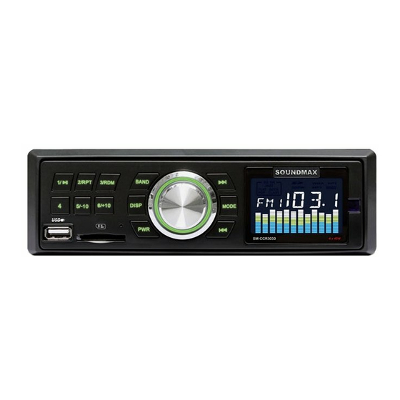
Control elements Front panel 1. 4 button 2. 1/PLAY/PAUSE button 3. 2/RPT button 4. 3/RDM button 5. DISP button 6. BAND button 7. SELECT button/VOLUME regulator button 9. MODE button 10. Display 11. USB port 12. 5/-10 button 13. SD/MMC memory card slot 14. -
Page 9: Lcd Layout
LCD layout 1. Graphic indicator of playback 2. Not active for this model 3. Digit display (frequency, track number, etc.) 4. Memory card playback indicator 5. USB playback indicator 6. MP3 playback indicator 7. Not active for this model 8. Repeat playback 9. -
Page 10: General Operations
General operations Turning the unit on/off Press PWR button to turn the unit on. Press the button again to turn the unit off. Mode select Press MODE button repeatedly to select between Radio, auxiliary input, USB or Memory Card modes. Modes of operation are indicated on the display. -
Page 11: Radio Operations
Radio operations Band select In Radio mode press BAND button to select a radio band: FM1, FM2 or FM3. 6 stations can be saved in each band making total 18 stations. Manual/automatic tuning Press buttons to start automatic search of the nearest station with strong signal in the current band downwards or upwards. -
Page 12: Usb/Sd/Mmc Operations
USB/SD/MMC operations Connecting a USB-device/memory card Insert a USB device into the USB port of this unit. Or insert an SD/MMC memory card until a click into the memory card slot. To remove the card, press it until a click, and then pull out from the slot. Note: USB/SD/MMC supported capacity: up to 8 Gb. -
Page 13: Troubleshooting Guide
Troubleshooting guide Below is a table describing simple measures that can help you eliminate most problems likely to emerge when this unit is in use. If below measures do not help, turn to a service center or to the nearest dealer. Symptom Cause Solution... -
Page 14: Specification
Specification General Maximum power output: 4 x 45 W Dimensions/weight: 177 x 150 x 50 mm/0.67 kg Suitable speaker impedance: 4 – 8 Ohm Fuse: 8 A/0.5 A Storage support: USB/SD/MMC up to 8 Gb Temperature range C – +60 FM Stereo Radio Frequency range: 87.5 –... - Page 15 ....................15 ...................16 ..................17 ...................18 ..................22 ..................23 .....................24 ....................25 USB- ............25 ............27 ................28...
- Page 18 « » (...
- Page 19 « » (...
- Page 20 – – –...
- Page 22 1/PLAY/PAUSE 2/RPT 3/RDM DISP BAND SELECT/ VOLUME MODE 11. USB- 5/-10 SD/MMC 6/+10...
- Page 24 PWR, MODE, , AUX, USB « » «USB» VOLUME. SELECT : VOL ( ) => BAS (bass - ) => TRE (treble - ) => BAL (balance - ) => FAD (fader - VOLUME, Bass/Treble: Balance: L15 ( R15 ( Fader: R15 ( F15 (...
- Page 25 BAND, : FM1, FM2 FM3. BAND; USB- USB- USB- USB- SD/MMC...
- Page 26 USB/SD/MMC- USB- FAT32. USB- 5/-10, 6/+10, 1/PLAY/PAUSE 2/RPT 3/RDM...
- Page 27 “ ”.
- Page 28 4 x 45 177 x 150 x 50 /0,67 4 – 8 8 A/0,5 A USB/SD/MMC C - +60 87,5 – 108,0 RCA (2 )
Need help?
Do you have a question about the SM-CCR3033 and is the answer not in the manual?
Questions and answers