Table of Contents
Advertisement
Quick Links
Advertisement
Table of Contents

Subscribe to Our Youtube Channel
Related Manuals for Maxim Integrated 78M6613


Summary of Contents for Maxim Integrated 78M6613
- Page 1 78M6613 Evaluation Board User Manual December 2011 Rev. 2 UM_6613_045...
- Page 2 Characteristics table are guaranteed. Other parametric values quoted in this data sheet are provided for guidance. Maxim Integrated 160 Rio Robles, San Jose, CA 95134 USA 1-408-601-1000 © Maxim Integrated The Maxim logo and Maxim Integrated are trademarks of Maxim Integrated Products, Inc.
-
Page 3: Table Of Contents
System Requirements ......................5 Safety and ESD Notes ......................6 Firmware Demo Code Introduction ..................6 Testing the 78M6613 Evaluation Board Prior to Shipping ............6 Installation ............................. 7 USB Driver Installation ......................7 Confirm COM Port Mapping ....................8 Basic Connection Setup ...................... - Page 4 Figure 3: ICE Adaptor ..........................13 Figure 4: Attaching the ICE Adaptor ....................... 13 Figure 5: 78M6613 Evaluation Board Electrical Schematic (1 of 2) ............14 Figure 6: 78M6613 Evaluation Board Electrical Schematic (2 of 2) ............15 Figure 7: 78M6613 Evaluation Board PCB Top View ................18 Figure 8: 78M6613 Evaluation Board PCB Bottom View ................
-
Page 5: Introduction
The Teridian™ 78M6613 Evaluation Board is an electrical measurement unit for performing measurements of up to two single-phase AC loads. It incorporates the 78M6613 power- and energy- measurement IC and connects to a PC through a USB cable such as the one provided in the demo kit. -
Page 6: Safety And Esd Notes
CLI, see the applicable Firmware Description Document. The 78M6613 is shipped with Firmware Demo Code Revision 1.0 or later loaded in the 78M6613 chip and included on the CD. The code revision can be verified by entering the command >i via the command line interface. -
Page 7: Installation
IC FT232R performs the USB functions. The FTDI driver for Windows presents a virtual COM port for enabling serial communications. Control of the 78M6613 Evaluation Board can be managed using a terminal emulation program. The FTDI Windows driver is a certified driver for Windows 2000 and Windows XP. -
Page 8: Confirm Com Port Mapping
78M6613 Evaluation Board User Manual UM_6613_045 2.2 Confirm COM Port Mapping 1. Launch the Control Panel and click on the System icon. 2. The System Properties screen appears. Click on the Hardware tab. Click on Device Manager. Under Ports (COM & LPT), look for the USB Serial Port assignment. -
Page 9: Basic Connection Setup
78M6613 Evaluation Board User Manual 2.3 Basic Connection Setup Figure 1 shows the basic connections of the 78M6613 Evaluation Board for use with external equipment. The 78M6613 Evaluation Board is powered through the USB cable. This same USB cable provides the communications link between the host PC and the 78M6613 Evaluation Board. -
Page 10: Figure 2: 78M6613 Evaluation Board Application Diagram
78M6613 Evaluation Board User Manual UM_6613_045 120/240V Host PC Single Phase AC Source 78M6613 Eval Board 3V3 Reg Current Shunt Voltage 78M6613 Divider UART Controller Optos 5x DIOs Load Under Test Figure 2: 78M6613 Evaluation Board Application Diagram Rev. 2... -
Page 11: Verify Serial Connection To The Pc
78M6613 Evaluation Board User Manual 2.4 Verify Serial Connection to the PC After connecting the USB cable from the 78M6613 Evaluation Board to the host PC, start the HyperTerminal application (or another suitable communication program) and create a session using the communication parameters shown in Table 1. - Page 12 78M6613 Evaluation Board User Manual UM_6613_045 Note that port parameters can only be adjusted when the connection is not active. It may be necessary to click the Disconnect Button to disconnect the port. FTDI COM Port Trouble-Shooting If the FTDI device driver did not install properly, there would be no assigned COM port number for the FTDI controller.
-
Page 13: In-Circuit Emulator (Ice) Adaptor
Figure 3: ICE Adaptor Figure 4 shows how to attach the ICE Adaptor to the 78M6613 Evaluation Board. Please make note of the orientation of the ICE Adaptor as to how it attaches to the 78M6613 Evaluation Board (V3P3 ICE Adaptor pin connects to the +V3P3 Evaluation Board pin). -
Page 14: Schematics, Bill Of Materials And Pcb Layouts
78M6613 Evaluation Board User Manual UM_6613_045 3 Schematics, Bill of Materials and PCB Layouts This section includes the schematics, bill of materials and PCB layouts for the 78M6613 Evaluation Board. 78M6613 Evaluation Board Schematics USB5P 0.1uF 0603 V3P3 0603 MS 810-C1608X5R1C105M... -
Page 15: Figure 6: 78M6613 Evaluation Board Electrical Schematic (2 Of 2)
MTGPS.PRT MTGPS.PRT MTGPS.PRT MTGPS.PRT MS 561-PS500A MS 561-PS500A MS 561-PS500A MS 561-PS500A Size Document Number 78M6613 Ev al Board Warning MAXIM Date: Tuesday , April 12, 2011 Sheet Figure 6: 78M6613 Evaluation Board Electrical Schematic (2 of 2) Rev. 2... -
Page 16: 78M6613 Evaluation Board Bill Of Materials
78M6613 Evaluation Board User Manual UM_6613_045 78M6613 Evaluation Board Bill of Materials Table 2: 78M6613 Evaluation Board Bill of Materials Digi-Key Item Qty Reference Part Footprint Part Number Manufacture ROHS (MS : Mouser) C1,C4,C5,C7,C11,C14, C15,C16,C18,C19,C23,C 0.1uF 0603 587-1243-1-ND UMK107B7104KA-T Taiyo Yuden... - Page 17 UM_6613_045 78M6613 Evaluation Board User Manual Digi-Key ROHS Item Qty Reference Part Footprint Part Number Manufacture (MS : Mouser) Sullins Connector TP2,TP8,TP9,TP10,TP11 TP/1 SIP100P1 S1011E-36-ND PBC36SAAN Solutions R2,R21 0603 P0.0GCT-ND ERJ-3GEY0R00V Panasonic - ECG R3,R5,R13,R14 0603 P1.00KHCT-ND ERJ-3EKF1001V Panasonic - ECG...
-
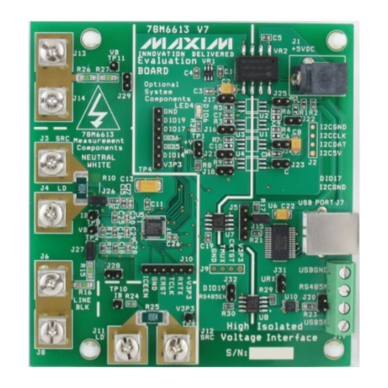
Page 18: 78M6613 Evaluation Board Pcb Layouts
78M6613 Evaluation Board User Manual UM_6613_045 3.3 78M6613 Evaluation Board PCB Layouts Figure 8: 78M6613 Evaluation Board PCB Bottom View Figure 7: 78M6613 Evaluation Board PCB Top View Rev. 2... -
Page 19: Ordering Information
UM_6613_045 78M6613 Evaluation Board User Manual 4 Ordering Information PART DESCRIPTION 78M6613-EVM-1 78M6613 Evaluation Board 5 Contact Information For more information about Maxim products or to check the availability of the 78M6613, contact technical support at www.maxim-ic.com/support. Rev. 2... -
Page 20: Revision History
78M6613 Evaluation Board User Manual UM_6613_045 Revision History REVISION REVISION PAGES DESCRIPTION NUMBER DATE CHANGED 1/11 Initial release Updated photos, schematics, BOM, and PCB layouts 5/11 5, 9, 13-18 for the Rev. 7 board. Replaced corporate logo. 12/11 Revised operating system requirements. - Page 21 Mouser Electronics Authorized Distributor Click to View Pricing, Inventory, Delivery & Lifecycle Information: Maxim Integrated 78M6613-EVM-1...
Need help?
Do you have a question about the 78M6613 and is the answer not in the manual?
Questions and answers