Table of Contents
Advertisement
Quick Links
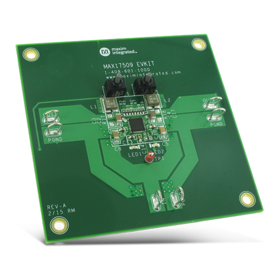
MAX17509 Evaluation Kit
General Description
The MAX17509 evaluation kit (EV kit) is a fully assembled
and tested circuit board to demonstrate the performance
of the MAX17509, a dual 3A, high-efficiency, synchronous
step-down DC-DC converter. The EV kit operates from a
4.5V to 16V input voltage to generate two, independent
3.3V and 1.2V outputs, with each regulator delivering
up to 3A continuous output current. The EV kit is preset
to the default 1MHz switching frequency for optimum
efficiency and component sizes, and each regulator
operates 180° out-of-phase to reduce input-voltage ripple
and total RMS input ripple current. The EV kit also
features adjustable input undervoltage-lockout (UVLO),
programmable frequency, external frequency synchro-
nization input, adjustable output voltage ranging from
0.904V to 3.782V and 4.756V to 5.048V with 20mV
resolution, selectable switching slew rate, adjustable soft-
start time with soft-stop option, power-good outputs, and
selectable overcurrent (OC) fault response to promote
design flexibility and system reliability.
Features
● Wide Input-Voltage Range (4.5V to 16V)
● 3.3V and 1.2V Output Voltages
● Up to 3A Output Current per Regulator
● Two Independent Outputs Operating 180° Out-of-
Phase
● 1MHz Switching Frequency
● External Frequency Synchronization Input
● Brickwall and Latchoff Overcurrent Response
(Selectable to Hiccup Response)
● Autoconfigured Internal Compensation
● Power-Good Output Indicator
● Independent Adjustable EN/UVLO Input
● Independent Adjustable Soft-Start Time with Soft-
Stop Option
● Selectable Switching Slew Rate for EMC Compliant
● Low-Profile and Small-Size, Surface-Mount
Components
● Fully Assembled and Tested
19-7670; Rev 0; 6/15
Evaluates: MAX17509 4.5V–16V,
Dual 3A Synchronous Buck Converter
Quick Start
Recommended Equipment
●
MAX17509 EV kit
●
4.5V to 16V, 4A DC input power supply
●
Two loads capable of sinking 3A
●
Digital voltmeters (DVM)
●
100MHz dual-trace oscilloscope
Procedure
The EV kit is fully assembled and tested. Follow the steps
below to verify board operation. Caution: Do not turn on
the power supply until all connections are completed.
1) Set the power supply at a voltage between 4.5V and
16V. Disable the power supply.
2) Connect the positive and negative terminals of the
power supply to IN and PGND PCB pads, respectively.
3) Connect the positive and negative terminals of the
first 3A load to OUT1 and PGND PCB pads, respec-
tively, and the second 3A load to OUT2 and PGND
PCB pads, respectively. Set both loads to 0A.
4) Connect the first DVM across the OUT1 and PGND
PCB pads, and the second across OUT2 and PGND,
respectively.
5) Change the position of SW1 and SW2 to position 1-2
(or 2-3) to enable the respective regulator. SW1 and
SW2 in the middle position will disable the device.
6) Enable the input power supply.
7) Verify that DVM1 displays 3.3V and DVM2 displays
1.2V.
8) Increase the load up to 3A to verify that DVM
continues displaying 3.3V and 1.2V, respectively.
Note that the EV kit is designed to demonstrate com-
pact solution-size so that the output voltage-sensing
is performed near C2 for VOUT1 and C3 for VOUT2.
Therefore, the output voltage is accurate across
those respective components.
Ordering Information
appears at end of data sheet.
Advertisement
Table of Contents

Subscribe to Our Youtube Channel
Related Manuals for Maxim Integrated MAX17509


Summary of Contents for Maxim Integrated MAX17509
-
Page 1: General Description
Evaluates: MAX17509 4.5V–16V, MAX17509 Evaluation Kit Dual 3A Synchronous Buck Converter General Description Quick Start The MAX17509 evaluation kit (EV kit) is a fully assembled Recommended Equipment and tested circuit board to demonstrate the performance ● MAX17509 EV kit of the MAX17509, a dual 3A, high-efficiency, synchronous ●... - Page 2 When the output voltage is changed, to 3A continuous output current. The switching frequency refer to the MAX17509 IC data sheet’s recommendation on is set to 1MHz to balance efficiency and component the inductance and capacitance selection criteria.
- Page 3 Evaluates: MAX17509 4.5V–16V, MAX17509 Evaluation Kit Dual 3A Synchronous Buck Converter Regulator Enable and Adjustable UVLO also capable of configuring different switching frequency options: 0.5MHz, 1MHz, 1.5MHz, and 2MHz for input voltage The device can be self-enabled by connecting EN_ to up to 6V.
- Page 4 1 and 1.2V on regulator 2. The target output voltage range. Consult the MAX17509 IC data sheet’s ) is determined by the sum of COARSE voltage recommendation on the inductance and capacitance...
-
Page 5: Load Regulation
Evaluates: MAX17509 4.5V–16V, MAX17509 Evaluation Kit Dual 3A Synchronous Buck Converter EV Kit Performance Report = 3.3V = 1.2V OUT1 OUT2 EFFICIENCY vs. OUTPUT CURRENT EFFICIENCY vs. OUTPUT CURRENT toc01 = 5V = 12V = 5V = 12V = 16V... - Page 6 Evaluates: MAX17509 4.5V–16V, MAX17509 Evaluation Kit Dual 3A Synchronous Buck Converter EV Kit Performance Report (continued) LOAD CURRENT TRANSIENT RESPONSE LOAD CURRENT TRANSIENT RESPONSE = 12V, V = 1.2V, I = 1.5–3A = 12V, V = 3.3V, I = 1.5 - 3A...
- Page 7 Figure 1. MAX17509 EV Kit Component Placement Guide— Figure 3. MAX17509 EV Kit PCB Layout—Component Side Component Side Figure 2. MAX17509 EV Kit Component Placement Guide— Figure 4. MAX17509 EV Kit PCB Layout—PGND Layer 2 Solder Side Maxim Integrated │ 7 www.maximintegrated.com...
-
Page 8: Ordering Information
Evaluates: MAX17509 4.5V–16V, MAX17509 Evaluation Kit Dual 3A Synchronous Buck Converter Figure 5. MAX17509 EV Kit PCB Layout—PGND Layer 3 Figure 6. MAX17509 EV Kit PCB Layout—Solder Side Component Information and Schematic Ordering Information See the following links for component information and... -
Page 9: Revision History
For pricing, delivery, and ordering information, please contact Maxim Direct at 1-888-629-4642, or visit Maxim Integrated’s website at www.maximintegrated.com. Maxim Integrated cannot assume responsibility for use of any circuitry other than circuitry entirely embodied in a Maxim Integrated product. No circuit patent licenses are implied. - Page 10 MAX17509 10UF OPEN 0.1UF 0.1UF 10UF OPEN PGND BST1 BST2 AVCC SYNC 200K LED1 LED2 OPEN OPEN 2.2UF PROJECT TITLE: MAX17509 EVKIT DRAWING TITLE: SIZE DATE: HARDWARE NUMBER: EPCB17509 2/3/2015 ENGINEER: DRAWN BY: REV: TEMPLATE REV: SHEET 2 OF 2...
- Page 11 BILL OF MATERIALS (BOM) 6/16/15 Revision Remarks QTY Component Manufacturer (Reference Designators) Per Description Part Number CAP CER 22UF 10V 10% X7R 1206 Murata GRM31CR71A226KE15 (10V, X7R, 10%) 1uF ±10%, 16V X7R ceramic capacitor (0603) Murata GRM188R71C105K 2.2uF ±10%, 10V X5R ceramic capacitor (0603) Murata GRM188R71A225K C9, C10 CAP CER 0.1UF 25V 10% X7R 0603...
Need help?
Do you have a question about the MAX17509 and is the answer not in the manual?
Questions and answers