Table of Contents
Advertisement
Quick Links
MAX2830 Evaluation Kit
General Description
The MAX2830 evaluation kit (EV kit) simplifies testing
of the MAX2830 receive and transmit performance in
802.11g/b applications operating in the 2.4GHz to 2.5GHz
ISM band. The EV kit provides 50Ω SMA connectors for
all RF and baseband inputs and outputs. Differential-to-
single-ended and single-ended-to-differential line drivers
are provided to convert the differential I/Q baseband
inputs and outputs to single ended.
Features
● On-Board Line Driver and Voltage Reference
● 50Ω SMA Connectors on All RF and Baseband Ports
● PC Control Software Available at
www.maximintegrated.com
Quick Start
Test Equipment Required
This section lists the recommended test equipment to
verify the operation of the MAX2830. It is intended as a
guide only and substitutions may be possible:
● MAX2830 EV kit
● INTF3000+ interface board
● DC supply capable of delivering +5V and 200mA of
continuous current
● DC supply capable of delivering -5V and 200mA of
continuous current
● DC supply capable of delivering +3.3V and 300mA of
continuous current
● DC supply capable of delivering +2.85V and 200mA
of continuous current
● One HP8648s or equivalent signal sources capable
of generating 0dBm up to 3GHz
● 802.11b/g CW I/Q waveform generator
● HP8561E or equivalent RF spectrum analyzer with a
minimum 100kHz to 3GHz frequency range
● TDS3012 or equivalent oscilloscope with 200MHz
bandwidth
● PC laptop or tablet with Microsoft Windows XP
®
Windows
7, 8 OS and a USB port
● USB-A male to USB-B male cable
Windows and Windows XP are registered trademarks and
registered service marks of Microsoft Corporation.
19-0926; Rev 3; 1/16
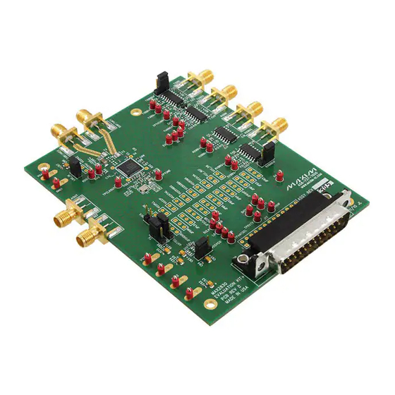
Connections and Setup
This section provides step-by-step instructions for getting
the EV kit up and running in all modes (see
EV kit connections):
1) Connect the PC to the INTF3000 interface board using
the USB-A male to USB-B male cable. On INTF3000,
remove jumper JU1 and connect a DC supply set to 3.3V
to the V
PULL
the INTF3000 (J4) directly to the 25-pin connector on the
EV kit (J18).
2) With the power supply turned off, connect a +2.85V
power supply to V
+3.3V power supply to V
supply ground to the header labeled GND1 or GND2.
3) With the power supply turned off, connect a +5V power
supply to the +5V test point and a -5V power supply to
the -5V test point. Connect the power-supply ground
to the header labeled GND1 or GND2. Connect all the
power-supply grounds together.
4) Make sure the jumpers are installed in their defualt
positions as shown in
5) Turn on the +3.3V power supply, followed by the
+2.85V power supply, +5V power supply, and -5V
power supply.
6) Install and run the MAX2830 control software,
available for download HERE.
Receive Mode
1)
Set the RXTX jumper across pins 2-3 (RX) to enable
the receiver and disable the transmitter. Set the
ANTSEL jumper across pins 2-3 (ANT1) to connect
the receiver to the ANT1 port, or pins 1-2 (ANT2) to
connect the receiver to the ANT2 port.
2)
Set the signal generator to accurately deliver
-100dBm at 2438MHz, at the SMA port (ANT1 or
ANT2) of MAX2830. Connect the output of signal
generator to ANT1 or ANT2 port of MAX2830.
3)
On the Registers page of the EV kit software, set
®
,
the registers to the recommended settings in the
MAX2830 data sheet by clicking the "Defaults" and
"Send All" buttons.
Evaluates: MAX2830
connector. Connect the 25-pin connector of
(pin 1) and V
REG
. Connect the power-
BAT
Figure
1.
Figure 1
for
, and a
CCAUX
Advertisement
Table of Contents

Related Manuals for Maxim Integrated MAX2830


Summary of Contents for Maxim Integrated MAX2830
-
Page 1: General Description
This section lists the recommended test equipment to 4) Make sure the jumpers are installed in their defualt verify the operation of the MAX2830. It is intended as a positions as shown in Figure guide only and substitutions may be possible: 5) Turn on the +3.3V power supply, followed by the... -
Page 2: Layout Considerations
Connect the Rx input to ANT1 Pins 1-2 Enables the buffers TXBBBUF/RXBBBUF Pins 2-3 Disables the buffers Pins 1-2 Short the jumper to provide voltage to the MAX2830 from the linear regulator (U10) Pins 2-3 Supply the V from V CCVCO CCVCO Pins 1-2... - Page 3 Evaluates: MAX2830 MAX2830 Evaluation Kit Figure 1. MAX2830 EV Kit Connections Maxim Integrated │ 3 www.maximintegrated.com...
-
Page 4: Ordering Information
Johnson Components www.johnsoncomponents.com Murata Americas www.murata.com Texas Instruments Inc. www.ti.com Note: Indicate that you are using the MAX2830 when contacting these component suppliers. Component List, PCB Layout, and Ordering Information Schematic PART TYPE See the following links for component information, PCB... -
Page 5: Revision History
For pricing, delivery, and ordering information, please contact Maxim Direct at 1-888-629-4642, or visit Maxim Integrated’s website at www.maximintegrated.com. Maxim Integrated cannot assume responsibility for use of any circuitry other than circuitry entirely embodied in a Maxim Integrated product. No circuit patent licenses are implied. - Page 6 DESIGNATION DESCRIPTION +5V, -5V, B1–B7, CSB, DIN, GND1, GND2, LD, RSSI, RXBBI+, RXBBI-, RXBBQ+, RXBBQ-, Test points RXHP,SCLK, SHDNB, TPANTSEL, TPCLKOUT, Keystone 5000 TPRXTX, TPTUNE, TPTXCMIN, TXBBI+ TXBBI-, TXBBQ+, TXBBQ-, VBAT, VCCAUX ANTSEL, RXBBBUF, RXTX, TXBBBUF, VCCVCO 1 x 3 headers Sullins PEC36SAAN CLKOUT, FREF, RXBBI, RXBBQ, RXRF/ANT1, SMA edge-mount connectors, round TXBBI, TXBBQ, TXRF/ANT2...
- Page 7 TI SN74LVTH244ADBR Not installed, (optional) Maxim MAX8882EUTJJ+ VCCLNA, VCCPA1, VCCPA2, VCCPLL, VCCRXBB1, VCCRXBB2, VCCRXMX, VCCTXMX, Not installed VCCXTAL, VCC_DB, VCC_REF, VREG 40MHz crystal Kyocera CX3225SB40000H0WZK21 Shunts (ANTSEL, LDO_IN, RXBBBUF, RXTX, TXBBBUF, — VCCVCO) Sullins SSC02SYAN — PCB: MAX2830/1/2 EVALUATION KIT...
-
Page 15: Maxim Integrated
Mouser Electronics Authorized Distributor Click to View Pricing, Inventory, Delivery & Lifecycle Information: Maxim Integrated MAX2830EVKIT+...
Need help?
Do you have a question about the MAX2830 and is the answer not in the manual?
Questions and answers