Advertisement
Quick Links
Maxim
>
Design Support
>
Maxim
>
Design Support
>
Keywords:
uC, evaluation kit, AFE, smart card, microcontroller, Rowley, IAR embedded workbench
APPLICATION NOTE 5388
Getting Started with the DS8005 Evaluation Kit
Apr 01, 2013
Abstract: This application note describes how to build, debug, and run applications on the on-board MAXQ622
microcontroller to interface with the DS8005 dual smart card interface. This is demonstrated in both IAR
Embedded Workbench and the Rowley CrossWorks IDE, using sample code provided with the kit.
Introduction
The
DS8005
dual smart card interface is a low-cost, dual analog front-end (AFE) for an IC card reader
interface that needs to communicate with two smart cards in a mutually exclusive fashion. The analog interface
is designed for use in ISO 7816, EMV
applications where the C4/C8 (AUX1/AUX2) contacts are not required on either card interface. The DS8005 is
designed to be used with microcontrollers that contain an ISO 7816 UART, or have the bandwidth to run this
protocol in software by bit-banging IO ports.
In the DS8005 evaluation kit (DS8005-KIT), the DS8005 is provided in a 28-pin SOIC package. A smaller 28-
pin TSSOP package is also available.
Setting Up the DS8005 Evaluation Kit
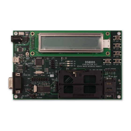
A photo of the DS8005 evaluation kit board is provided in Figure 1. The following hardware components are
contained in the evaluation kit and are used for implementing and verifying the demonstrated program:
1. DS8005 evaluation kit board
2. On-board
MAXQ622
3. USB-to-JTAG dongle for programming the MAXQ622
4. One ACOS3 smart card
5. Two card sockets (one smart card and one SIM/SAM card)
6. 2-line liquid-crystal display (LCD) screen for the user interface
7. Level-shifted RS-232 interface for debugging and the user interface
8. Pushbuttons for reset and user input
9. Regulated power supply (5V, ±5%, 300mA, center positive)
Table 1 shows all the jumpers and includes a description of what each setting does. Settings highlighted in
blue indicate the default settings. See Figure 2 for jumper locations.
Technical Documents
>
Application Notes
Technical Documents
>
Application Notes
®
, and B-CAS applications. Additionally, the device is designed for
microcontroller for developing smart card applications
>
Interface Circuits
> APP 5388
>
Microcontrollers
> APP 5388
Page 1 of 22
Advertisement

Related Manuals for Maxim Integrated DS8005


Summary of Contents for Maxim Integrated DS8005
- Page 1 ISO 7816 UART, or have the bandwidth to run this protocol in software by bit-banging IO ports. In the DS8005 evaluation kit (DS8005-KIT), the DS8005 is provided in a 28-pin SOIC package. A smaller 28- pin TSSOP package is also available.
- Page 2 Figure 1. The DS8005 evaluation kit. Page 2 of 22...
- Page 3 The interface A card presence indicator (SIM/SAM card) is connected to Closed ground. This pin is active high. The MAXQ622 is not able to supply a clock signal to the DS8005; an external Open clock is needed in socket XY1.
- Page 4 If you have difficulty installing the FTDI drivers correctly using the driver setup executable provided on the DS8005 evaluation kit CD, you can download and unpack the standard driver package, available on FTDI's website at www.ftdichip.com/Drivers/VCP.htm. The driver package can be downloaded from this page and will be named similar to “CDM20814_WHQL_Certified.zip”, where the five-digit number depends on the exact...
- Page 5 See also www.ftdichip.com/Support/Documents/AppNotes.htm for additional information from FTDI. Determining the COM Port Location of the USB-to-Serial Interface The USB-to-serial interface provided by the FT232RL chip on the USB-to-JTAG dongle uses the virtual COM port (VCP) device model on Windows. This means that the USB-to-serial bridge appears as a standard COM port and can be used by any Windows application that has the ability to communicate over a COM port.
- Page 6 executable, check the DRVSTORE directory, usually found in the Windows directory under the System32 subdirectory. If you see directories named ftdibus_<xxxxx> or ftdiport_<xxxxx>, where <xxxxx> is a random- appearing string of hex digits, delete these directories before running the CDM20814_Setup.exe executable. This will remove the preinstalled copies of the drivers and allow the drivers to reinstall cleanly.
- Page 7 Figure 4. Advanced settings for the VCP driver. In this dialog box, find the Latency Timer field shown above in the BM Options section. Change this field from its existing value (likely 16 or something similar) to 1 (which is the lowest possible value). Click OK, and then click OK again in the previous Properties window to complete the change.
- Page 8 Use the red indicator to make sure pin 1 of the adapter’s JTAG header is connected to the TCK pin of the JTAG header on the DS8005 (Figure 7). Ensure that the jumper settings on the board are on their default...
- Page 9 Figure 7. The USB-to-serial adapter connected to the JTAG header on the DS8005 with a standard 10-pin ribbon cable. Figure 8. MTK2 after successfully connecting to the MaxQ Bootloader. Finally, to load the example code, select File Master Erase if the option is not already selected (indicated by a check mark), then select File Load Code and locate and open the DS8005_EK.hex file.
- Page 10 power to the board. Figure 9. MTK2 after successfully loading the provided hex file onto the MAXQ622. Compiling, Debugging, and Running Code in the IAR Embedded Workbench The example code in this evaluation kit was written and tested with version 2.30 of the IAR Systems Embedded Workbench.
- Page 11 Figure 10. Opening an existing workspace on IAR startup. Page 11 of 22...
- Page 12 Figure 11. Opening up the sample code workspace in IAR. All the project options should be correctly set. However, the COM port will need to be changed to match the VCP of the USB-to-serial adapter. Right-click on the project and select Options (Figure 12). Page 12 of 22...
- Page 13 Figure 12. Modifying the project options in IAR. In the Options dialog box, select the Debugger tab (Figure 13). Select JTAG from the Driver drop-down menu. Now select the JTAG subtab just below the Debugger tab (Figure 14). Change the COM port accordingly and click OK.
- Page 14 Figure 13. Selecting the JTAG driver in IAR. Page 14 of 22...
- Page 15 IAR menu (Figure 15). Figure 15. Debugging shortcut buttons in IAR. To stop debugging, select Debug Stop Debugging from the menu. To then run the code, push the reset button on the DS8005 evaluation kit board. Page 15 of 22...
- Page 16 Compiling, Debugging, and Running Code in Rowley CrossWorks The example code in this evaluation kit was written and tested with version 2.1.0.2011101107.12397 of Rowley CrossWorks. This section describes how to compile, run, and debug the example code with Rowley. It may be necessary to reconnect the USB-to-serial adapter to avoid problems while trying to connect to the device.
- Page 17 Figure 17. Rebuilding the sample code in Rowley. Next, connect to the USB-to-serial adapter by first selecting View Targets, then selecting View Property Window to view the targets and target properties. These windows will appear on the right. Inside the Targets window, select Maxim Serial JTAG Adapter (Figure 18).
- Page 18 Figure 19. Selecting the COM port for the Serial JTAG Adapter in Rowley. Next, select Target Connect Maxim Serial JTAG Adapter to connect to the USB-to-serial adapter (Figure 20). If successful, a message on the bottom left of the window will confirm the connection and a status indicator at the bottom right of the window will show a yellow circle and “Maxim Serial JTAG adapter”...
- Page 19 To run and debug the program, select Debug Go. Rowley will download the code onto the MAXQ622, with the progress displayed in the output window at the bottom. Once done, a disassembly window will appear on the left and a yellow arrow will point to the start of code, since Rowley also automatically places a breakpoint at the start of main.
- Page 20 Figure 23. Selecting the Dumb Terminal option from the initial Select device dialog box in MTK2. The serial port will need to be reconfigured before opening it, as it will still be configured to the VCP of the USB-to-serial adapter. From the MTK menu, select Options Configure Serial Port.
- Page 21 The smart card reader (MAXQ622) properly manages the sending and receiving of application protocol data units (APDUs), as defined in the EMV specifications, to the ACOS3 smart cards supplied in the DS8005-KIT. This is used to demonstrate typical payment transactions. The four transactions implemented in the example code are: 1.
- Page 22 Related Parts DS8005 Smart Card Interface Free Samples DS8005-KIT Evaluation Kit for the DS8005 MAXQ622 16-Bit Microcontrollers with Infrared Module and Optional Free Samples More Information For Technical Support: http://www.maximintegrated.com/support For Samples: http://www.maximintegrated.com/samples Other Questions and Comments: http://www.maximintegrated.com/contact Application Note 5388: http://www.maximintegrated.com/an5388...
Need help?
Do you have a question about the DS8005 and is the answer not in the manual?
Questions and answers