Advertisement
General Description
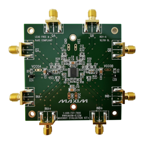
The MAX9601 evaluation kit (EV kit) is a fully assem-
bled and tested surface-mount PCB that evaluates the
MAX9601 dual-channel PECL output comparators. It
can be used to evaluate the MAX9601's performance in
tracking high-fidelity narrow pulses, as well as conform
its low-propagation delay and delay dispersion. The
differential input stage accepts a wide range of signals
in the common-mode range from (VEE + 3V) to (VCC -
2V). The outputs are complementary digital signals with
external components necessary to observe the PECL
serial-data output on a 50I input oscilloscope. The
board also provides layout options that allow the output
termination to be modified easily for alternate output
terminations, such as +5V PECL and high impedance
or AC-coupled level translation. The EV kit features test
points to control the complementary latch-enable control
inputs. The EV kit also provides resistor footprints to
evaluate the MAX9601's adjustable hysteresis feature.
DESIGNATION
QTY
C1, C13,
4
C17, C22
C5, C8,
4
C11, C20
C6, C9,
4
C12, C19
C7, C10,
4
C18, C21
INA+, INA-,
INB+, INB-, QA,
8
QA, QB, QB
For pricing, delivery, and ordering information, please contact Maxim Direct
at 1-888-629-4642, or visit Maxim's website at www.maximintegrated.com.
DESCRIPTION
0I Q5% resistors (0603)
10FF Q10%, 10V X7R ceramic
capacitors (1206)
Murata GRM31CR71A106K
TDK C3216X7R1A106K
0.1FF Q10%, 50V X7R ceramic
capacitors (0603)
Murata GRM188R71H104K
TDK C1608X7R1H104K
0.01FF Q10%, 50V X7R ceramic
capacitors (0603)
Murata GRM188R71H103K
TDK C1608X7R1H103K
Edge-mount receptacle SMA
connectors
MAX9601 Evaluation Kit
Evaluates: MAX9601
-2.2V to +3V Input Range with +5V/-5.2V Supplies
S
-1.2V to +4V Input Range with +6V/-4.2V Supplies
S
SMA Connectors to Access Differential Inputs and
S
Outputs
Differential PECL Outputs
S
Latch Enable
S
Adjustable Hysteresis
S
Output Terminated for Interfacing with a 50I
S
Oscilloscope Input
Allows Alternate Output Terminations
S
Fully Assembled and Tested
S
PART
MAX9601EVKIT+
+Denotes lead(Pb)-free and RoHS compliant.
DESIGNATION
QTY
LEA, LEA,
4
LEB, LEB
R1, R4,
4
R10, R13
R2, R3,
4
R11, R12
R6, R8, R9,
6
R15, R17, R18
R7, R16
2
R19–R22,
8
R27–R30
U1
1
—
1
Features
Ordering Information
TYPE
EV Kit
Component List
DESCRIPTION
Test points
4.53I Q1% resistors (0603)
82.5I Q1% resistors (0603)
49.9I Q1% resistors (0603)
16.5kI Q1% resistors (0603)
90.9I Q1% resistors (0603)
Dual PECL high-speed
comparator (20 TSSOP)
Maxim MAX9601EUP+
PCB: MAX9601 EVALUATION
KIT+
19-5092; Rev 0; 12/09
Advertisement
Table of Contents

Related Manuals for Maxim Integrated MAX9601EVKIT+


Summary of Contents for Maxim Integrated MAX9601EVKIT+
-
Page 1: General Description
MAX9601 Evaluation Kit Evaluates: MAX9601 General Description Features The MAX9601 evaluation kit (EV kit) is a fully assem- -2.2V to +3V Input Range with +5V/-5.2V Supplies bled and tested surface-mount PCB that evaluates the -1.2V to +4V Input Range with +6V/-4.2V Supplies MAX9601 dual-channel PECL output comparators. -
Page 2: Quick Start
Disable the signal generator. (MAX9600/MAX9601) section in the MAX9601 IC data 10) Connect the signal generator to the edge-mount sheet for a more detailed description. SMA connector marked INA+. 11) Enable all power supplies. Enable the signal generator. Maxim Integrated... -
Page 3: Output Termination
For accurate measure- last known output state) ment of the device’s rise and fall times, an oscilloscope with a bandwidth several times larger than the maximum Invalid condition (output is in unknown state) signal frequency must be used. Maxim Integrated... - Page 4 MAX9601 Evaluation Kit Evaluates: MAX9601 Figure 1. MAX9601 EV Kit Schematic Maxim Integrated...
- Page 5 MAX9601 Evaluation Kit Evaluates: MAX9601 1.0” 1.0” Figure 2. MAX9601 EV Kit Component Placement Guide— Figure 3. MAX9601 EV Kit Component PCB Layout— Component Side Component Side 1.0” Figure 4. MAX9601 EV Kit PCB Layout—Solder Side Maxim Integrated...
- Page 6 Maxim Integrated cannot assume responsibility for use of any circuitry other than circuitry entirely embodied in a Maxim Integrated product. No circuit patent licenses are implied. Maxim Integrated reserves the right to change the circuitry and specifications without notice at any time. The parametric values (min and max limits) shown in the Electrical Characteristics table are guaranteed.
Need help?
Do you have a question about the MAX9601EVKIT+ and is the answer not in the manual?
Questions and answers