Table of Contents
Advertisement
Quick Links
Advertisement
Table of Contents

Subscribe to Our Youtube Channel
Related Manuals for Miranda SDM-771p


Summary of Contents for Miranda SDM-771p
- Page 2 This equipment has been tested and complies with the limits in accor- dance with the specifications in: - FCC Part 15, Subpart B - CE EN50081-1:1992 - CE EN50082-1:1992. How to contact us: For technical assistance, please contact the Miranda Technical Support cen- tre nearest you: Americas Asia Telephone: Telephone:...
-
Page 3: Table Of Contents
Guide to Installation and Operation Contents page 1 SDM-771p AES/EBU Digital to Analog Converter ..1 1.1 Introduction............... 1 1.2 Features..............1 2 Overall View ..............2 3 Installation ..............4 3.1 Power Supply............4 3.2 AES Input..............4 3.3 Analog Output............5 4 Operation ................ -
Page 5: Sdm-771P Aes/Ebu Digital To Analog Converter
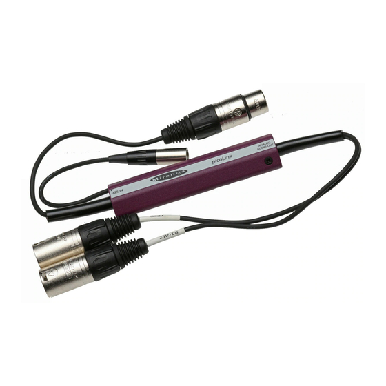
This module is available in two versions, depending on the stan- dard selected: SDM-771p/110: symmetric AES3 110 Ω / XLR input asymmetric AES3-id 75 Ω or SP-Dif / BNC input SDM-771p/75: Figure 1 Functional Block Diagram 1.2 Features... -
Page 6: Overall View
SDM-771P/75/110 2 Overall view The figures below represents the SDM-771P/75 and the SDM- 771P/110. The input is connected to the BNC socket over 75 Ω and to a three-point XLR connector over 110 Ω. A multicolor LED indicates the status of the AES-EBU carrier. A mini DE-EMPH switch is used to configure the de-emphasis cir- cuit. - Page 7 Guide to Installation and Operation Figure 2.2 SDM-771p, 110 Ω Version...
-
Page 8: Installation
Each power supply provides a regulated +5VDC@750mA power source. Plug the power supply into a wall or power bar outlet. The SDM-771p uses a mini XLR-3 connector for its power needs; figure 3.1 provides a detailed pinout of the male connector. -
Page 9: Analog Output
Guide to Installation and Operation Figure 3.2 Female XLR connector pinout Signal + Signal _ 3.3 Analog Output SDM-771p/75 & SDM-771p/110: Refer to the Configuration section to set the signal output level and the de-emphasis type. Figure 3.3 Male XLR connector pinout Signal +... -
Page 10: Operation
SDM-771P/75/110 4 Operation 4.1 Configuring the switches Figure 5 Switch Location Configuring the left output level Configuring the right output level Configuring de-emphasis Level Switches The level of each stereo output can be set using the two three- position LEFT & RIGHT switches... - Page 11 Guide to Installation and Operation Green: The SDM-711p is turned on and the AES-EBU carrier is valid. Yellow: The audio signal from the AES-EBU carrier is invalid (validity bit) Red: The AES-EBU carrier is invalid (no signal detected, biphase coding error, parity error) Off: The unit is not powered on.
-
Page 12: Specifications
SDM-771P/75/110 5 Specifications Measurement Conditions AES input, sampling frequency: 48 kHz outputs 0 dBFS = +24 dBu loaded on 10 kΩ AES3-110Ω INPUT 110 Ω Input impedance: Maximum level: 10 Vcc Minimum level: 0.2 Vcc AES3-75 Ω INPUT (SP-Dif - COMPATIBLE) 75 Ω... - Page 13 Guide to Installation and Operation Attenuation of sine-shaped jitter 100 kHz: 20 dB Display: 1 multicolored LED, three functions 670 µsec. @ 48 kHz Processing time: Maximum power consumption: 10 K load: 1.2 W 600 Ω load:...
Need help?
Do you have a question about the SDM-771p and is the answer not in the manual?
Questions and answers