Table of Contents
Advertisement
Quick Links
Guide to Installation and Operation
Copyright 2002 Miranda Technologies Inc.
imaging Series
ASD - 111i
M293-9900-201
Specifications may be subject to change.
Printed in Canada
August 2002
Miranda
Technologies inc.
3499 Douglas-B.-Floreani
St-Laurent, Québec, Canada H4S 1Y6
Tel. 514-333-1772
Fax. 514-333-9828
www.miranda.com
4:2:2 Component
Analog to Digital
Converter
Advertisement
Table of Contents

Related Manuals for Miranda ASD-111i


Summary of Contents for Miranda ASD-111i
- Page 1 4:2:2 Component imaging Series Analog to Digital ASD - 111i Converter Guide to Installation and Operation M293-9900-201 Copyright 2002 Miranda Technologies Inc. Specifications may be subject to change. Printed in Canada August 2002 Miranda Technologies inc. 3499 Douglas-B.-Floreani St-Laurent, Québec, Canada H4S 1Y6 Tel.
- Page 3 Equipment that fails after the warranty period, has been operated or installed in a manner other than that specified by Miranda, or has been subjected to abuse or modification, will be repaired for time and material charges at the Buyer’s expense.
-
Page 4: Electromagnetic Compatibility
Out-Of Warranty Equipment Updates and Spare Parts Policy Miranda Technologies’ current pricing structure for out-of-warranty equipment updates, or the sale of spare parts, is available from Miranda Technical Support Services at (514) 333-1772. ELECTROMAGNETIC COMPATIBILITY - This equipment has been tested for verification of compliance with FCC Part 15, Subpart B, class A requirements for Digital Devices. -
Page 5: Table Of Contents
Contents ASD-111i 4:2:2 Analog to Digital Converter............1.1 Introduction......................1 1.2 Features....................... 1 Installation........................ 3 2.1 ASD-111i Mechanical Installation................ 3 2.1.1 imaging Quartet, Quartet-C and Quartet-M Housing Frame...... 2.1.2 imaging Symphonie Housing Frame............3 2.1.2 imaging Solo Housing Frame..............2.2 Rear Panel Label....................4 2.2.1 imaging Quartet/Quartet-C/Quartet-M/Solo Connector Label.... -
Page 7: Asd-111I 4:2:2 Analog To Digital Converter
4:2:2 outputs conform to the SMPTE 259M standard. The ASD-111i is a member of the imaging family of digital video cards and therefore requires the imaging Quartet, Quartet-C or Quartet-M, imaging Solo or imaging Symphonie housing frame for mounting and power. - Page 8 • Automatic input calibration • Pre-calibration for 11 formats • EDH Insertion (as per SMPTE-165M) • Built-in color bars • Black on loss of signal • Horizontal centering adjustment • External or sync-on-green sync selection • Masking capability of incoming vertical ancillary data •...
-
Page 9: Installation
Symphonie or Solo imaging housing frames in order to provide power to the card. This section describes how to install the ASD-111i in any of these housing frames. It is not necessary to switch off the power from these housing frames when installing the SDM-111i. -
Page 10: Rear Panel Label
2.2 Rear Panel Label 2.2.1 imaging Quartet/Quartet-C/Quartet-M/Solo Connector Label A connector label has been shipped with your ASD-111i. This label is to be installed on the housing frame's rear panel in order to identify the ASD-111i external connectors. To install the label, follow these steps. -
Page 11: Asd-111I Electrical Installation
Rear module 2.3 ASD-111i Electrical Installation When connecting the ASD-111i to external equipment, make sure that all serial digital connections are point-to-point. For instance, there must be a point-to-point connection between a 4:2:2 OUT BNC and target equipment. If a T-connector is used to connect other equipment, the maximum specified cable length is no longer valid. - Page 12 CAV inputs Supported CAV input formats include GBR, SMPTE/EBU, Betacam, and MII. After installing the CAV inputs make sure to program the ASD-111i for the appropriate input format. Refer to section 3, Operation. 4:2:2 Serial digital video outputs 4:2:2 Serial digital component video signals are provided on the BNC connectors labeled 4:2:2 OUT (1 to 3).
-
Page 13: Operation
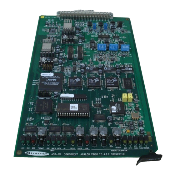
3 Operation 3.1 ASD-111i User Interface Figure 3.1 outlines the ASD-111i's user interface situated at the front end of the card. The interface components include, from left to right: • Line format status and error detection. • Input signal format selection. -
Page 14: Line Format Status And Error Detection
The following indicators provide information on the ASD-111i's line format status. Refer to Figure 3.1 for the correct indicator location. • This LED lights up to indicate the ASD-111i has detected a CAV input with a 525 line format. •... -
Page 15: Input Signal Format Selection
3.3 Input Signal Format Selection The ASD-111i must be informed on the type of CAV input installed. The choices of CAV inputs, as they successively appear when scrolled through, is shown in Figure 3.3 below. In order to program the appropriate format, use the FORMAT push-button to scroll through the choices of CAV inputs. -
Page 16: Manual Calibration Of Gain, Offset And Horizontal Centering
3. Depress the CALIB. push-button for more than 2 seconds in order to execute automatic calibration. For several seconds, the ASD-111i will attempt to conform the output 4:2:2 signal to the SMPTE 259M standard. During this time, the ERR calibration LED will flicker. The flickering will stop automatically after a complete and successful calibration. -
Page 17: Recalling Default Values
1. Make sure the ASD-111i is programmed for the type of input CAV signal being processed. Use the FORMAT push-button to make any modifications. Refer to the note following this procedure. 2. Depress the SELECT push-button. The Y GAIN, B-Y GAIN and R-Y GAIN LEDs light up. -
Page 18: Vertical Ancillary Data Masking
V ANC jumper. Perform the following steps in order to mask vertical ancillary data or to allow it to pass through the ASD-111i. 1. Locate the V ANC jumper situated on the left side of the ASD-111i (refer to figure 3.2 for location). -
Page 19: Specifications
1. Locate the CORING jumper (LK2) situated on the left side of the ASD-111i (refer to figure 3.2 for location). 2. To enable the coring function set the jumper in the ON position. In order to remove the coring effect, set the jumper in the OFF position. -
Page 21: Schematic Diagrams
5 Schematic DIagrams...
Need help?
Do you have a question about the ASD-111i and is the answer not in the manual?
Questions and answers