Table of Contents
Advertisement
Quick Links
DVC-800/820
Guide to Installation and Operation
Copyright 2003 Miranda Technologies Inc.
M619-9900-200
Specifications may be subject to change.
Printed in Canada
August 2003
Miranda
Technologies inc.
3499 Douglas-B.-Floreani
St-Laurent, Québec, Canada H4S 1Y6
Tel. 514-333-1772
Fax. 514-333-9828
www.miranda.com
Downconverter
and DV Encoder
for HD Acquisition
Advertisement
Table of Contents

Subscribe to Our Youtube Channel
Related Manuals for Miranda DVC-800


Summary of Contents for Miranda DVC-800
- Page 1 Downconverter DVC-800/820 and DV Encoder for HD Acquisition Guide to Installation and Operation M619-9900-200 Copyright 2003 Miranda Technologies Inc. Specifications may be subject to change. Printed in Canada August 2003 Miranda Technologies inc. 3499 Douglas-B.-Floreani St-Laurent, Québec, Canada H4S 1Y6 Tel.
- Page 2 Miranda Technologies Inc. warrants that the equipment it manufactures shall be free from defects in materials and workmanship for a period of two (2) years from the date of shipment from the factory. If equipment fails due to such defects, Miranda will provide repair of the failed unit under the terms of the Miranda warranty.
- Page 3 St. Laurent (Montreal), Que. H4S 1Y6 France Tokyo, Japan 108-0073 Canada +1 (514) 333-1772 +33 1 55 86 87 88 +81 3 5730 2988 +1 (514) 333-6914 +33 1 55 86 00 29 +81 3 5730 2973 Toll free: 1-800-224-9828 www.miranda.com ii | DVC-800/820...
-
Page 4: Table Of Contents
GUIDE TO INSTALLATION AND OPERATION Table of Contents 1 DVC-800/820 Downconverter and DV Encoder for HD Acquisition ......1 1.1 Introduction...............................1 1.2 Features ..............................2 2 Installation........................4 2.1 Unpacking..............................4 2.2 Mechanical Installation – DVC-800 on Sony cameras ................4 2.3 Mechanical Installation – DVC-820 on Panasonic cameras ..............5 2.4 Electrical Installation..........................5... - Page 5 GUIDE TO INSTALLATION AND OPERATION iv | DVC-800/820...
-
Page 6: Dvc-800/820 Downconverter And Dv Encoder For Hd Acquisition
Panasonic Varicam (DVC-820). The DVC-800/820 provides a unique combination of outputs and functionality to facilitate monitoring, review and approval, rough cut editing and the preparation of dailies while on set. Designed in cooperation with a number of electronic acquisition pioneers, the DVC-800/820 is the indispensable tool for electronic acquisition. -
Page 7: Features
Pass-through mode formats (to HD SDI out only) 1920x1080i/60 1920x1080p/30sF 1920x1080p/24sF 720p/60 Automatic or Manual selection between HD SDI or HDCAM SONY video input (DVC-800 only) Video Output Two (2) HD SDI outputs including: Four (4) embedded audio channels ATC video time code (line 10) - Page 8 Replaces channel 4 of the embedded audio when present Can be inserted in DV as metadata Distinct graticule markers settings in DV playback mode and in normal mode Default configuration settings: for burned-in information and the user marker Locked audio not supported for DVCPRO DVC-800/820 | 3...
-
Page 9: Installation
GUIDE TO INSTALLATION AND OPERATION 2 Installation 2.1 Unpacking Make sure the following items have been shipped with your DVC-800/820. If any of the following items are missing, contact your distributor or Miranda Technologies Inc. • DVC-800 or DVC-820 Downconverter and DV encoder for HD Acquisition •... -
Page 10: Mechanical Installation - Dvc-820 On Panasonic Cameras
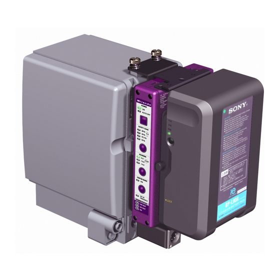
The Sony HDCAM connector is integral to the mounting bracket of the DVC-800, and connection is made when the DVC-800 is mounted on the rear of the camera body. As well, the external DC input is passed through the DVC-800. -
Page 11: Inputs And Outputs
GUIDE TO INSTALLATION AND OPERATION 2.4.2 Inputs and Outputs All remaining input and output connectors are located on the side of the DVC-800/820 body. The figure shows the location of the various connectors. DIP switches LTC in HD SDI in... -
Page 12: Serial Communication Connector (Rs-232) Layout
Two threaded holes (6-32; maximum penetration 3/16” or 0.188”) are provided on the camera side of the DVC-800/820 to allow custom brackets to be attached for the mounting of external accessories. See Fig. 2.6. Fig. 2.6 Threaded holes for mounting accessory support brackets... -
Page 13: Configuration
The figure below illustrates a production configuration involving all of the inputs and outputs available on the DVC-800/820. Observe how master recordings, dailies, on-set monitoring and off-line post-production capabilities are all supported and facilitated through the use of the DVC-800/820. Subsets of this configuration may be appropriate for less complex production situations. -
Page 14: Operation
Illuminates when Centre Mark is turned ON (either size) Note: Two different sets of settings for the markers are stored in the DVC-800/820 - one for the down-converter mode, and one for the DV playback mode. These settings are memorised and retained when the unit is turned off. -
Page 15: Dip Switches
GUIDE TO INSTALLATION AND OPERATION 4.2.6 Dip Switches There are 16 dip-switches located on the upper side panel of the DVC-800/820, laid out as shown in the figure below. F R : 2 3 . 9 8 / 2 9 . 9 7 / 5 9 . 9 4... -
Page 16: Video Operation
4.4 Video Operation 4.4.1 Video Source Selection If DV is present on the IEEE1394 input to the DVC-800/820, it is by default converted and sent to the SD video outputs (composite,Y,SDI). When there is no DV input to the DVC-800, the output is derived from one of the two HD inputs:... - Page 17 GUIDE TO INSTALLATION AND OPERATION Figure 4.3 Marker configurations 12 | DVC-800/820...
-
Page 18: On-Screen Display (Osd) Configuration
The user-defined fields allow the display of almost anything on the screen. The configuration of the OSD can be accomplished using software available on Miranda’s web site. Software is available for both PC and PDA platforms. For more information on how to configure the OSD, see section 4.7.2. -
Page 19: Dv Operation & External Device Control
Locked audio is not supported for the DVCPRO25 format. This can be a problem for some DVCPRO VTRs that will not accept the DVCPRO stream from the DVC-800. To be able to record the DVCPRO stream on a DVCPRO VTR, the user might have to select a different audio source than the one included in the stream. - Page 20 The HD CAM connector is proprietary to Sony, and is located at the rear of their cameras. There is always an audio signal, either voice, tone or mute. Audio 3 and 4 from the external AES IN of the DVC-800 is always routed to the camera through this connector. HD SDI IN: The audio found in group 1 of the HD VIDEO IN is disembedded.
-
Page 21: Time Code Operation
800/820 will not read the time code embedded in the HD SDI input signal if an external LTC signal is present. • When no time code source is present, the DVC-800/820 generates its own time code. This is necessary for DV to work properly and also for the frame rate converter. 16 | DVC-800/820... -
Page 22: User Bits
4.7.2 Control Mode In Control Mode, the RS-232 port is connected to a PC or PDA running software created by Miranda. This software allows the user to perform three functions: •... -
Page 23: Specifications
GUIDE TO INSTALLATION AND OPERATION 5 Specifications 5.1 Input Specifications HD SIGNAL 20-bit Y-Pb-Pr HD as per HDW-F900 Sony Interface (DVC-800 only) FORMAT 1920x1080i/59.94 SMPTE-274M 1920x1080i/60 SMPTE-274M 1920x1080p/30sF SMPTE-274M 1920x1080p/29.97sF SMPTE-274M 1920x1080i/50 SMPTE-274M 1920x1080p/25sF SMPTE-295M 1920x1080p/24sF SMPTE-274M 1920x1080p/23.98sF SMPTE-274M 1280x720p/59.94... -
Page 24: Power Specifications
< 600 Ω IMPEDANCE < 70 dB Ref 0 dBFS (A weighted) CONNECTOR Hirose 6-pin (HR10A series) AUDIO CAM (3/4) per Sony HDW-F900 (DVC-800 only) LEVEL: LVTTL, 3.3V CONNECTOR 50-pin camera connector, as per Sony HDW-F900 5.3 Power Specifications POWER INPUT: 11 –... -
Page 25: Time Code
2fr compensation 1fr delay DVITC HD DVITC Transparent Transparent Transparent = Remains unprocessed, i.e. Out = In Compensation = Time code is compensated for delays Delay = The user bits will lag the video by 1 frame. 20 | DVC-800/820...
Need help?
Do you have a question about the DVC-800 and is the answer not in the manual?
Questions and answers