Victor CUTMASTER Operating Manual
12mm plasma cutting system
Hide thumbs
Also See for CUTMASTER:
- Service manual (80 pages) ,
- Operating manual (80 pages) ,
- Operating manual (84 pages)

Related Manuals for Victor CUTMASTER


Summary of Contents for Victor CUTMASTER
- Page 1 380- 400V CUTMASTER 12mm ® PLASMA CUTTING SYSTEM Operating Manual Art # A-09205_AB Revision: AI Issue Date: December 5, 2013 Manual No.: 0-5076 VictorThermalDynamics.com...
- Page 2 WE APPRECIATE YOUR BUSINESS! Congratulations on your new Victor Thermal Dynamics product. We are proud to have you as our customer and will strive to provide you with the best service and reliability in the industry. This product is backed by our extensive warranty and world-wide service network. To locate your nearest distributor or service agency call 1-800-426-1888, or visit us on the web at www.VictorThermalDynamics.com.
- Page 3 Plasma Cutting Power Supply CutMaster 12mm ® SL60 1Torch™ Operating Manual Number 0-5076 Published by: Victor Technologies International, Inc. 82 Benning Street West Lebanon, New Hampshire, USA 03784 (603) 298-5711 www.victorthermaldynamics.com Copyright 2008, 2009, 2010, 2011, 2012, 2013 by Victor Technologies International, Inc.
- Page 4 This Page Intentionally Blank...
-
Page 5: Table Of Contents
Table of Contents SECTION 1: GENERAL INFORMATION ................1-1 1.01 Notes, Cautions and Warnings ................. 1-1 1.02 Important Safety Precautions ................... 1-1 1.03 Publications ......................1-2 1.04 Note, Attention et Avertissement ................1-3 1.05 Precautions De Securite Importantes ............... 1-3 1.06 Documents De Reference .................. - Page 6 Table of Contents PATENT INFORMATION ...................4T-12 SECTION 5 SYSTEM: SERVICE ..................5-1 5.01 General Maintenance ....................5-1 5.02 Maintenance Schedule....................5-2 5.03 Common Faults ......................5-2 5.04 Fault Indicator ......................5-3 5.05 Basic Troubleshooting Guide ..................5-4 5.06 Power Supply Basic Parts Replacement ..............5-6 SECTION 5 TORCH: SERVICE ..................
-
Page 7: Section 1: General Information
CUTMASTER 12mm SECTION 1: GENERAL INFORMATION GASES AND FUMES Gases and fumes produced during the plasma cutting process can be dangerous and hazardous to your health. 1.01 Notes, Cautions and Warnings • Keep all fumes and gases from the breathing area. Keep your head out of the welding fume plume. -
Page 8: Publications
CUTMASTER 12mm • Protect others in the work area from the arc rays. Use protective booths, screens or shields. FIRE AND EXPLOSION • Use the shade of lens as suggested in the following per Fire and explosion can be caused by hot slag, sparks, or the ANSI/ASC Z49.1: plasma arc. Minimum Protective Suggested • Be sure there is no combustible or flammable material Arc Current Shade No. Shade No. in the workplace. Any material that cannot be removed Less Than 300* must be protected. -
Page 9: Note, Attention Et Avertissement
CUTMASTER 12mm 8. NFPA Standard 51, OXYGEN-FUEL GAS SYSTEMS FOR WELDING, CUTTING AND ALLIED PROCESSES, obtainable from the National Fire Protection Association, Batterymarch AVERTISSEMENT Park, Quincy, MA 02269 Toute procédure pouvant provoquer des blessures 9. NFPA Standard 70, NATIONAL ELECTRICAL CODE, obtain- de l’opérateur ou des autres personnes se trouvant... - Page 10 CUTMASTER 12mm • Les sortes de gaz et de fumée provenant de l’arc de plasma dépendent du genre de métal utilisé, des revêtements se INCENDIE ET EXPLOSION trouvant sur le métal et des différents procédés. Vous devez prendre soin lorsque vous coupez ou soudez tout métal Les incendies et les explosions peuvent résulter des scories pouvant contenir un ou plusieurs des éléments suivants: chaudes, des étincelles ou de l’arc de plasma. Le procédé à l’arc antimoine cadmium mercure de plasma produit du métal, des étincelles, des scories chaudes pouvant mettre le feu aux matières combustibles ou provoquer...
-
Page 11: Documents De Reference
CUTMASTER 12mm Nuance Minimum Nuance Suggerée 4. Norme ANSI Z87.1, PRATIQUES SURES POUR LA PRO- TECTION DES YEUX ET DU VISAGE AU TRAVAIL ET DANS Courant Arc Protective Numéro Numéro LES ECOLES, disponible de l’Institut Américain des Normes Moins de 300* Nationales (American National Standards Institute), 1430... -
Page 12: Declaration Of Conformity
The product is designed and manufactured to a number of standards and technical requirements. Among them are: Harmonized Standard of “EMC Directive” EN 60974-10:2007 Arc Welding Equipment - Part 10: Electromagnetic compatibility (EMC) requirements Harmonized Standard of “Low Voltage Directive” EN 60974-1:2012 Arc Welding Equipment - Part 1: Welding power sources. (Supersedes Standard EN 60974-1:2005) Extensive product design verification is conducted at the manufacturing facility as part of the routine design and manufacturing process. This is to ensure the product is safe, when used according to instructions in the manual and related industry standards, and performs as specified. Rigorous testing is incorporated into the manufacturing process to ensure the manufactured product meets or exceeds all design specifications. Victor Technologies. has been manufacturing products for more than 30 years, and will continue to achieve excellence in our area of manufacture. Manufacturer’s Authorized Representative Steve Ward V.P. Europe and General Manager Address: Victor Technologies International Inc. Europa Building (Signature) Chorley N Industrial Park Chorley, Lancashire, Steve Ward England PR6 7BX Full Name Date: March 18, 2014 V.P. Europe and General Manager... - Page 13 CUTMASTER 12mm Classification: The equipment described in this manual is Class A and intended for industrial use. WARNING This Class A equipment is not intended for use in residential locations where the electrical power is provided by the public low-voltage supply system. There may be potential difficulties in ensuring electromagnetic compatibility in those locations, due to conducted as well as radiated disturbances.
-
Page 14: Statement Of Warranty
Victor Thermal Dynamics Corporation will honor warranty claims submitted within the warranty periods listed below. All warranty periods begin on the date of sale of the product to the original retail customer or 1 year after sale to an authorized Victor Thermal... -
Page 15: Section 2 System: Introduction
Owner’s Manual number and equipment identification numbers. Electronic copies of this manual can also be downloaded at no charge in Acrobat PDF format by going to the Victor Thermal Dynamics web site listed below and clicking on Thermal Dynamics and then on the Literature link: http://www.victorthermaldynamics.com... -
Page 16: Power Supply Specifications
Input Power 400 VAC (360 - 440 VAC), Three Phase, 50/60 Hz NOTE: Some CutMaster 12mm models will only operate on 380-400V. Please check your machine † before attempting to run on any of the other voltages that are listed above. -
Page 17: Input Wiring Specifications
CUTMASTER 12mm 2.05 Input Wiring Specifications CutMaster 12mm Power Supply Input Cable Wiring Requirements Input voltage Freq Power Input Suggested Sizes Flexible Cord Volts I max I eff Fuse (amps) (AWG) 50/60 3 Phase 50/60 Line Voltages with Suggested Circuit Protection and Wire Sizes... -
Page 18: Power Supply Features
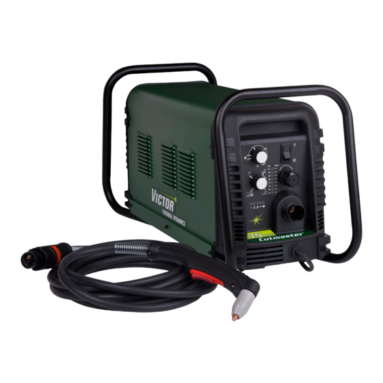
CUTMASTER 12mm 2.06 Power Supply Features Handle and Leads Wrap Control Panel Torch Leads Receptacle Art # A-07942 Work Cable and Clamp Port for Optional Automation Interface Cable Filter Assembly Gas Inlet Port Art # A-08544 Input Power Cord INTRODUCTION... -
Page 19: Section 2 Torch: Introduction
CUTMASTER 12mm SECTION 2 TORCH: 2. Mechanized Torch, Model INTRODUCTION The standard machine torch has a position- ing tube with rack & pinch block assembly. 15.875" / 403 mm 2T.01 Scope of Manual 9.285" / 236 mm This manual contains descriptions, operating instructions and maintenance procedures for the 1Torch Models SL60/ 1.175"... -
Page 20: 04 Options And Accessories
CUTMASTER 12mm G. Gas Requirements Manual and Mechanized Torch Gas Specifications Gas (Plasma and Secondary) Compressed Air Operating Pressure 60 - 95 psi Refer to NOTE 4.1 - 6.5 bar Maximum Input Pressure 125 psi / 8.6 bar Power 300 - 500 scfh... - Page 21 CUTMASTER 12mm E. Parts - In - Place (PIP) The torch includes a 'Parts - In - Place' (PIP) circuit. When the shield cup is properly installed, it closes a switch. The torch will not operate if this switch is open.
- Page 22 CUTMASTER 12mm This Page Intentionally Blank 2T-4 INTRODUCTION Manual 0-5076...
-
Page 23: Section 3 System: Installation
CUTMASTER 12mm SECTION 3 SYSTEM: Three-Phase (3ø) and Jumper Settings INSTALLATION Jumper L1 -L4 3.01 UNPACKING 1. Use the packing lists to identify and account for each item. 2. Inspect each item for possible shipping damage. If damage is evident, contact your distributor and / or shipping company before proceeding with the installation. -
Page 24: Gas Connections
CUTMASTER 12mm 8. Reinstall the Power Supply cover per instructions found Installing Optional Single - Stage Air Filter in section 5. An optional filter kit is recommended for improved filtering with 9. Connect the opposite end of individual wires to a cus- compressed air, to keep moisture and debris out of the torch. - Page 25 CUTMASTER 12mm Installing Optional Two - Stage Air Filter Kit Using High Pressure Air Cylinders This optional two - stage air line filter is also for use on When using high pressure air cylinders as the air supply: compressed air shop systems. Filter removes moisture and 1.
- Page 26 CUTMASTER 12mm This Page Intentionally Blank INSTALLATION Manual 0-5076...
-
Page 27: Section 3 Torch: Installation
If necessary, connect the torch to the Power Supply. Connect only the Victor Thermal Dynamics model SL60 / Manual or SL100 / Mechanical Torch to this power supply. Maximum torch leads length is 100 feet / 30.5 m, including extensions. - Page 28 CUTMASTER 12mm This Page Intentionally Blank 3T-2 INSTALLATION Manual 0-5076...
-
Page 29: Section 4 System: Operation
CUTMASTER 12mm SECTION 4 SYSTEM: OPERATION 4.01 Front Panel Controls / Features See Illustration for numbering Identification 1. Output Current Control Sets the desired output current. Output settings up to 40 Amps may be used for drag cutting (with the torch tip contacting the workpiece) or standoff cutting. -
Page 30: Preparations For Operation
/ 4.8 - 5.9 bar (LED's in center of control panel). Torch Connection Refer to the Standoff chart for pressure setting details. Check that the torch is properly connected. Only Victor Thermal Dynamics model SL60 / Manual or SL100 / Me- chanical Torches may be connected to this Power Supply. - Page 31 CUTMASTER 12mm Shutdown DRAG CutMaster 12mm Gas Pressure Turn the ON / OFF switch to OFF (down). All Settings Power Supply indicators shut OFF. Unplug the input power Leads SL60 cord or disconnect input power. Power is removed from Length (Hand Torch) the system.
- Page 32 CUTMASTER 12mm This Page Intentionally Blank OPERATION Manual 0-5076...
-
Page 33: Section 4 Torch: Operation
CUTMASTER 12mm SECTION 4 TORCH: 3. Install the replacement Electrode by pushing it straight into the torch head until it clicks. OPERATION 4 . Install the starter cartridge and desired tip for the operation into the torch head. 4T.01 Torch Parts Selection 5. -
Page 34: 03 General Cutting Information
CUTMASTER 12mm Cut Surface NOTE The desired or specified condition (smooth or rough) of Handle torch leads with care and protect them the face of the cut. from damage. Nitride Build - Up Piloting Piloting is harder on parts life than actual cutting... -
Page 35: 04 Hand Torch Operation
CUTMASTER 12mm and can be easily scraped off. "High speed dross" usually 4. Slide the trigger release toward the back of the torch forms a narrow bead along the bottom of the cut edge and handle while simultaneously squeezing the trigger. The is very difficult to remove. - Page 36 CUTMASTER 12mm 8. For a consistent standoff height from the workpiece, heat protection. Choose the holding technique that install the standoff guide by sliding it onto the torch feels most comfortable and allows good control and shield cup. Install the guide with the legs at the sides movement.
-
Page 37: 05 Gouging
CUTMASTER 12mm NOTE torch handle. Gas vents through this gap as part of normal operation. Do not attempt to force the When the shield cup is properly installed, there shield cup to close this gap. Forcing the shield cup is a slight gap between the shield cup and the against the torch head or torch handle can damage torch handle. -
Page 38: 06 Mechanized Torch Operation
CUTMASTER 12mm Standoff Distance The tip to work distance affects gouge quality and depth. CAUTION Standoff distance of 1/8 - 1/4 inch (3 - 6 mm) allows for Touching the torch tip or shield cup to the work smooth, consistent metal removal. Smaller standoff dis- surface will cause excessive parts wear. - Page 39 CUTMASTER 12mm D i r e c t i o n o f T o r c Standoff Distance r a v Straight Arc Trailing Arc A-02586 Leading Arc Mechanized Torch Operation For optimum smooth surface quality, the travel speed should be adjusted so that only the leading edge of the arc column produces the cut.
-
Page 40: 07 Parts Selection For Manual And Mechanized Torch Cutting
9-8241 9-8237 Tips: Tip Gouging A 9-8225 (40 Amps Max.) NOTE CutMaster 52 uses 60A and less Tip Gouging B 9-8226 (50 - 100 Amps) CutMaster 82 uses 80A and less CutMaster 102 uses 100A and less Art # A-08065_AE... -
Page 41: 08 Recommended Cutting Speeds For Sl60 Torch With Exposed Tip
CUTMASTER 12mm 4T.08 Recommended Cutting Speeds for SL60 Torch With Exposed Tip Type Torch: SL60 With Exposed Tip Type Material: Mild Steel Type Plasma Gas: Air Type Secondary Gas: Single Gas Torch Thickness Output Amperage Speed (Per Minute) Standoff Plasma Gas Press... -
Page 42: 09 Recommended Cutting Speeds For Sl60 Torch With Shielded Tip
CUTMASTER 12mm 4T.09 Recommended Cutting Speeds for SL60 Torch With Shielded Tip Type Torch: SL60 With Shielded Tip Type Material: Mild Steel Type Plasma Gas: Air Type Secondary Gas: Single Gas Torch Thickness Output Amperage Speed (Per Minute) Standoff Plasma Gas Press... -
Page 43: Patent Information
CUTMASTER 12mm PATENT INFORMATION Plasma Cutting Torch Patents The following parts are covered under U.S. and Foreign Patents as follows: Catalog # Description Patent(s) 9-8215 Electrode US Pat No(s) 6163008; 6987238 Other Pat(s) Pending 9-8213 Cartridge US Pat No(s) 6903301; 6717096; 6936786;... - Page 44 CUTMASTER 12mm Catalog # Description Patent(s) 9-8245 Shield Cap US Pat No(s) 6914211; D496951 Other Pat(s) Pending The following parts are also licensed under U.S. Patent No. 5,120,930 and 5,132,512: Catalog # Description 9-8235 Shield Cap 9-8236 Shield Cap 9-8237...
- Page 45 CUTMASTER 12mm Manual 0-5076 OPERATION 4T-13...
- Page 46 CUTMASTER 12mm This Page Intentionally Blank 4T-14 OPERATION Manual 0-5076...
-
Page 47: Section 5 System: Service
CUTMASTER 12mm SECTION 5 SYSTEM: SERVICE 5.01 GENERAL MAINTENANCE Maintain more often Warning! if used under severe Disconnect input power before maintaining. conditions Each Use Visual check of torch tip and electrode Weekly Visually inspect the cables and leads. Replace as needed... -
Page 48: Maintenance Schedule
4. Worn torch parts 5. Cutting current too low. Daily Operational Checks or Every Six Cutting Hours: 6. Non - Genuine Victor Thermal Dynamics parts used Check torch consumable parts, replace if damaged 7. Incorrect gas pressure or worn. -
Page 49: Fault Indicator
CUTMASTER 12mm 5.04 FAULT INDICATOR At initial power up, two lights will temporarily illuminate for 2-3 seconds to show the version of software used. To determine the first digit, count the function indicators left to right, 1 through 5. To determine the second digit count the pressure indicators, reading from bottom to top, 0 through 7. -
Page 50: Basic Troubleshooting Guide
CUTMASTER 12mm 5.05 BASIC TROUBLESHOOTING GUIDE WARNING There are extremely dangerous voltage and power levels present inside this unit. Do not attempt to diagnose or repair unless you have had training in power electronics measurement and troubleshooting techniques. Problem - Symptom Possible Cause... - Page 51 CUTMASTER 12mm Problem - Symptom Possible Cause Recommended Action FAULT & 80 PSI 1. Torch shield cup is loose. 1. Tighten shield cup by hand. Do not overtighten. indicators flashing. 2. Torch tip, electrode or starter 2. Turn OFF power supply. Remove shield cup. Install Gas flow is cycling cartridge missing.
-
Page 52: Power Supply Basic Parts Replacement
CUTMASTER 12mm 1. Remove power from the power supply; turn OFF the 5.06 POWER SUPPLY BASIC PARTS REPLACEMENT gas supply and bleed down the system. 2. Remove the system cover. See "A Cover Removal" in this section. WARNING 3. Locate the internal air line and the fitting from the filter Disconnect primary power to the system before assembly. - Page 53 CUTMASTER 12mm NOTE If replacing or cleaning just the filter element refer Housing to the following illustration for disassembly. Filter Element (Cat. No. 9-7741) Spring Filter Element O-ring (Cat. No. 9-7743) Assembled Filter Cover Barbed Fitting Art # A-02476 Optional Single-Stage Filter Element Replacement 5.
- Page 54 CUTMASTER 12mm 3. Loosen the two bolts on the top of the Filter Assembly enough to allow the Filter Elements to move freely. 4. Note the location and orientation of the old Filter Ele- ments. 5. Slide out the old Filter Elements.
-
Page 55: Section 5 Torch: Service
CUTMASTER 12mm SECTION 5 TORCH: SERVICE Upper Groove 5T.01 GENERAL MAINTENANCE with Vent Holes Must Remain Open NOTE Upper O-Ring Refer to Previous "Section 5 System" for common in Correct Groove and fault indicator descriptions. Threads Cleaning Torch Lower O-Ring... -
Page 56: 02 Inspection And Replacement Of Consumable Torch Parts
CUTMASTER 12mm 4. Remove the tip. Check for excessive wear (indicated 5T.02 INSPECTION AND REPLACEMENT OF by an elongated or oversized orifice). Clean or replace CONSUMABLE TORCH PARTS the tip if necessary. Good Tip Worn Tip WARNING Disconnect primary power to the system before disassembling the torch or torch leads. -
Page 57: Section 6: Parts Lists
Description Catalog # CutMaster 12mm CE Power Supply with 400/415VAC, 3 Phase, 50 Hz, with input power cable 3-5130-4 CutMaster 12mm Non CE Power Supply with 400/415VAC, 3 Phase, 50 Hz, with input power cable 3-5130-3 Manual 0-5076 PARTS LIST... -
Page 58: Replacement Power Supply Parts
CUTMASTER 12mm 6.04 Replacement Power Supply Parts Description Catalog # Regulator 9-0115* Filter Assembly Replacement Element 9-0116 Input Power Cord for 400 V Power Supply 9-0218 NOTE *9-0115 regulator, If the serial number of the power supply is prior to #05078755 then kit number 9-0201 will be needed to replace not only the regulator (9-0115) but the logic PCB as well. -
Page 59: Replacement Parts For Hand Torch
CUTMASTER 12mm 6.06 Replacement Parts for Hand Torch Item # Description Catalog # Torch Handle Replacement Kit (includes items No. 2 & 3) 9-7030 Trigger Assembly Replacement Kit 9-7034 Handle Screw Kit (5 each, 6-32 x 1/2” cap screw, and wrench) 9-8062 Torch Head Assembly Replacement Kit (includes items No. -
Page 60: Replacement Parts - For Machine Torches With Unshielded Leads
CUTMASTER 12mm 6.07 Replacement Parts - for Machine Torches with Unshielded Leads Item No. Description Catalog No. Torch Head Assembly without leads (includes items 2, 3, and 14) 9-8220 Large O-Ring 8-3487 Small O-Ring 8-3486 PIP Switch Kit 9-7036 Unshielded Automated Leads Assemblies with ATC connectors 5 - foot / 1.5 m Leads Assembly with ATC connector... - Page 61 CUTMASTER 12mm 5 & 6 A-07994_AB Manual 0-5076 PARTS LIST...
-
Page 62: Replacement Shielded Machine Torch Leads Assemblies
CUTMASTER 12mm 6.08 Replacement Shielded Machine Torch Leads Assemblies Item No. Description Catalog No. Mechanized Shielded Leads Assemblies with ATC Connectors 5 - foot / 1.5 m Leads Assembly with ATC Connector 4-7846 10 - foot / 3.05 m Leads Assembly with ATC Connector 4-7847 25 - foot / 7.6 m Leads Assembly with ATC Connector... -
Page 63: Torch Consumable Parts (Sl60)
9-8241 9-8237 Tips: Tip Gouging A 9-8225 (40 Amps Max.) NOTE CutMaster 52 uses 60A and less Tip Gouging B 9-8226 (50 - 100 Amps) CutMaster 82 uses 80A and less CutMaster 102 uses 100A and less Art # A-08065_AE... -
Page 64: Torch Consumable Parts (Sl100)
CUTMASTER 12mm 6.10 Torch Consumable Parts (SL100) Ohmic Clip Automation Torch Ohmic Clip 9-8224 Manual Torch 9-8259 20-40A Shield Tip: Shield Cap, Machine Cup Body, STANDOFF 40A 9-8245 9-8237 CUTTING 9-8205 Shield Cap, Deflector Shield Cup 9-8206 9-8243 9-8218 9-8208... -
Page 65: Appendix 1: Sequence Of Operation (Block Diagram
CUTMASTER 12mm APPENDIX 1: SEQUENCE OF OPERATION (BLOCK DIAGRAM) ACTION: ACTION: ACTION: ACTION: RUN / Rapid Auto Restart / ON / OFF switch to ON Close external RUN / SET / LATCH disconnect switch. Rapid Auto Restart / switch to RUN... -
Page 66: Appendix 2: Data Tag Information
CUTMASTER 12mm APPENDIX 2: DATA TAG INFORMATION West Lebanon, NH USA 03784 Manufacturer's Name and/or Logo, Location, Model and Revision Level, Serial Number M odel : and Production Code Dat e of M f r : Made in USA Type of Power... -
Page 67: Appendix 3: Torch Pin - Out Diagrams
CUTMASTER 12mm APPENDIX 3: TORCH PIN - OUT DIAGRAMS A. Hand Torch Pin - Out Diagram ATC Female Receptacle ATC Male Connector Front View Front View Negative / Negative / Plasma Plasma 8 - Open 8 - Ground 4 - Green /... -
Page 68: Appendix 4: Torch Connection Diagrams
CUTMASTER 12mm APPENDIX 4: TORCH CONNECTION DIAGRAMS A. Hand Torch Connection Diagram Torch: SL60 / SL100 Hand Torch Leads: Torch Leads with ATC Connector Power Supply: with ATC Receptacle Male ATC Leads ATC Female Power Connector Receptacle Torch Torch Supply... - Page 69 CUTMASTER 12mm This Page Intentionally Blank Manual 0-5076 APPENDIX...
-
Page 70: Appendix 5: System Schematic, 380/400/415V Units
CUTMASTER 12mm APPENDIX 5: SYSTEM SCHEMATIC, 380/400/415V UNITS PRI 1 PRI 1 PRI 2 PRI 2 PRI 4 PRI 4 PRI 3 PRI 3 BIAS SUPPLY MTH1 MTH1 MTH2 MTH2 +12VDC + C1-C4* + C1-C4* CHOKE /INRUSH CE UNITS ONLY... - Page 71 CUTMASTER 12mm 1TORCH PIP SWITCH PIP SWITCH SEC1 SEC1 SEC2 SEC2 CHOKE1 CHOKE1 +12VDC TORCH SWITCH TORCH SWITCH TEMP /OVERTEMP ATC CONNECTOR CIRCUIT AUTOMATION TORCH SOLENOID -V OUT 1 -V OUT 1 ELECTRODE1 ELECTRODE1 TIP1 TIP1 PILOT IGBT PILOT IGBT...
- Page 72 CUTMASTER 12mm This Page Intentionally Blank APPENDIX Manual 0-5076...
- Page 73 CUTMASTER 12mm This Page Intentionally Blank Manual 0-5076 APPENDIX...
-
Page 74: Appendix 6: Publication History
Updated ART A-07994 per ECOB2136. Dec. 5, 2013 Updated Declaration of Conformity. Made the following rebranding changes: updated cover to show new Victor Thermal Dynamics trade dress, updated thank you text, changed headers and footers, updated rear cover. A-10 APPENDIX... - Page 75 This Page Intentionally Blank...
- Page 76 I N N O V A T I O N T O S H A P E T H E W O R L D ™ U.S. Customer Care: 800-426-1888 / FAX 800-535-0557 Canada Customer Care: 905-827-4515 / FAX 800-588-1714 International Customer Care: 940-381-1212 / FAX 940-483-8178 Printed in Mexico © 2012 Victor Technologies International, Inc. www.victortechnologies.com...
Need help?
Do you have a question about the CUTMASTER and is the answer not in the manual?
Questions and answers