
Related Manuals for Victor CUTMASTER 102


Summary of Contents for Victor CUTMASTER 102
- Page 1 400V 460V 600V 208/230V CUTMASTER ™ PLASMA CUTTING SYSTEM Service Manual Art # A-08618_AD Revision: AM Issue Date: September 4, 2014 Manual No.: 0-4998 VictorThermalDynamics.com...
- Page 2 WE APPRECIATE YOUR BUSINESS! Congratulations on your new Victor Thermal Dynamics product. We are proud to have you as our customer and will strive to provide you with the best service and reliability in the industry. This product is backed by our extensive warranty and world-wide service network. To locate your nearest distribu- tor or service agency call 1-800-426-1888, or visit us on the web at www.thermal-dynamics.com.
- Page 3 Plasma Cutting Power Supply CutMaster ® SL100 1Torch™ Service Manual Number 0-4998 Published by: Victor Technologies International, Inc. 82 Benning Street West Lebanon, New Hampshire, USA 03784 (603) 298-5711 www.thermal-dynamics.com Copyright 2008, 2009, 2010, 2012, 2013 by Victor Technologies International, Inc.
- Page 4 This Page Intentionally Blank...
-
Page 5: Table Of Contents
TABLE OF CONTENTS SECTION 1: GENERAL INFORMATION ..................1-1 1.01 Notes, Cautions and Warnings ..............1-1 1.02 Important Safety Precautions ..............1-1 1.03 Publications ....................1-2 1.04 Note, Attention et Avertissement ..............1-3 1.05 Precautions De Securite Importantes ............1-3 1.06 Documents De Reference ................1-5 1.07 Statement of Warranty ................1-6 SECTION 2 SYSTEM: INTRODUCTION ..................2-1 2.01... - Page 6 TABLE OF CONTENTS SECTION 5 SYSTEM: SERVICE ......................5-1 5.01 General Maintenance .................5-1 5.02 Maintenance Schedule ................5-2 5.03 Common Faults ..................5-2 5.04 Fault Indicator .....................5-3 5.05 Basic Troubleshooting Guide ..............5-5 5.06 Circuit Fault Isolation ..................5-7 5.07 Main Input and Internal Power Problems ..........5-10 5.08 Pilot Arc Problems ..................5-15 5.09...
-
Page 7: Section 1: General Information
CUTMASTER 102 SECTION 1: GENERAL INFORMATION GASES AND FUMES Gases and fumes produced during the plasma cutting process can be dangerous and hazardous to your health. 1.01 Notes, Cautions and Warnings • Keep all fumes and gases from the breathing area. Keep Throughout this manual, notes, cautions, and warnings are your head out of the welding fume plume. -
Page 8: Publications
CUTMASTER 102 • Keep helmet and safety glasses in good condition. Re- • Install and maintain equipment according to NEC code, place lenses when cracked, chipped or dirty. refer to item 9 in Subsection 1.03, Publications. • Disconnect power source before performing any service • Protect others in the work area from the arc rays. Use protective booths, screens or shields. or repairs. • Use the shade of lens as suggested in the following per • Read and follow all the instructions in the Operating ANSI/ASC Z49.1:... -
Page 9: Note, Attention Et Avertissement
CUTMASTER 102 10. NFPA Standard 51B, CUTTING AND WELDING PROCESSES, 1.05 Precautions De Securite obtainable from the National Fire Protection Association, Bat- Importantes terymarch Park, Quincy, MA 02269 11. CGA Pamphlet P-1, SAFE HANDLING OF COMPRESSED GASES IN CYLINDERS, obtainable from the Compressed Gas Associa- tion, 1235 Jefferson Davis Highway, Suite 501, Arlington, VA 22202 AVERTISSEMENTS 12. CSA Standard W117.2, CODE FOR SAFETY IN WELDING AND L’OPÉRATION ET LA MAINTENANCE DU MATÉ-... - Page 10 CUTMASTER 102 • Pour des informations sur la manière de tester la fumée et les gaz de votre lieu de travail, consultez l’article 1 et les documents cités à la page 5. INCENDIE ET EXPLOSION • Utilisez un équipement spécial tel que des tables de coupe Les incendies et les explosions peuvent résulter des scories à débit d’eau ou à courant descendant pour capter la fumée chaudes, des étincelles ou de l’arc de plasma.
-
Page 11: Documents De Reference
CUTMASTER 102 4. Norme ANSI Z87.1, PRATIQUES SURES POUR LA PRO- Nuance Minimum Nuance Suggerée Courant Arc Protective Numéro Numéro TECTION DES YEUX ET DU VISAGE AU TRAVAIL ET DANS LES ECOLES, disponible de l’Institut Américain des Normes Moins de 300* Nationales (American National Standards Institute), 1430 300 - 400*... -
Page 12: Statement Of Warranty
Victor Thermal Dynamics Corporation will honor warranty claims submitted within the warranty periods listed below. All warranty periods begin on the date of sale of the product to the original retail customer or 1 year after sale to an authorized Victor Thermal Dynamics Distributor. -
Page 13: Section 2 System: Introduction
Electronic copies of this manual can also be downloaded at no charge in Acrobat PDF format by going to the Victor Thermal Dynamics web site listed below and clicking on Thermal Dynamics and then on the Literature link: http://www.victorthermaldynamics.com... -
Page 14: Power Supply Specifications
Power Supply includes input cable. Output Current 30 - 100 Amps, Continuously Adjustable Power Supply Gas Particulates to 5 Microns Filtering Ability CutMaster 102 Power Supply Duty Cycle * Ambient Tempera- Duty Cycle Ratings @ 40° C (104° F) ture Operating Range 0° - 50° C All Units... -
Page 15: Input Wiring Specifications
CUTMASTER 102 2.05 Input Wiring Specifications CutMaster 102 Power Supply Input Cable Wiring Requirements Input volt- Freq Power Input Suggested Sizes Volts I max I1eff Fuse (amps) Flexible Cord (Min. AWG) 1 Phase 50/60 20.6 4 Type W 50/60 21.9 4 Type W 50/60 27.6... -
Page 16: Power Supply Features
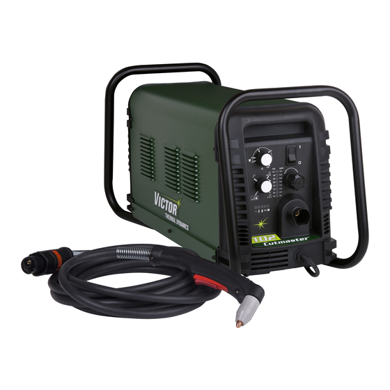
CUTMASTER 102 2.06 Power Supply Features Handle and Leads Wrap Control Panel Torch Leads Receptacle Art # A-08359 Work Cable and Clamp Port for Optional Automation Interface Cable Input Power Selection Filter Assembly Gas Inlet Port Art # A-08360 Input Power Cord... -
Page 17: Section 2 Torch: Introduction
CUTMASTER 102 SECTION 2 TORCH: 2. Mechanized Torch, Model INTRODUCTION The standard machine torch has a positioning tube with rack & pinch block assembly. 15.875" / 403 mm 9.285" / 236 mm 2T.01 Scope of Manual This manual contains descriptions, operating instructions and maintenance procedures for the 1Torch Models SL100/Manual 1.175"... -
Page 18: 04 Options And Accessories
CUTMASTER 102 G. Gas Requirements Manual and Mechanized Torch Gas Specifications Gas (Plasma and Secondary) Compressed Air Operating Pressure 60 - 95 psi Refer to NOTE 4.1 - 6.5 bar Power Maximum Input Pressure 125 psi / 8.6 bar Supply... - Page 19 CUTMASTER 102 D. Main Cutting Arc Remote Pendant DC power is also used for the main cutting arc. The nega- tive output is connected to the torch electrode through the torch lead. The positive output is connected to the workpiece via the work cable and to the torch through a...
- Page 20 CUTMASTER 102 This Page Intentionally Blank INTRODUCTION Manual 0-4998 2T-4...
-
Page 21: Section 3 System: Installation
CUTMASTER 102 SECTION 3 SYSTEM: The following illustration and directions are for changing phase of the power supply. INSTALLATION Input Power Cable Connections Single-Phase (1ø) and Jumper Settings Three-Phase (3ø) Store copper jumpers on base plate 3.01 Unpacking 1. Use the packing lists to identify and account for each item. -
Page 22: Gas Connections
CUTMASTER 102 6. Connect the wires as follows. • Wires to L1, L2 and L3 input. It does not matter CAUTION what order these wires are attached. See previous The primary power source and power cable must illustration and on label in the power supply. conform to local electrical code and the recom- • Green / Yellow wire to Ground. - Page 23 CUTMASTER 102 Installing Optional Single - Stage Air Filter Installing Optional Two - Stage Air Filter Kit An optional filter kit is recommended for improved filtering with This optional two - stage air line filter is also for use on compressed air, to keep moisture and debris out of the torch.
- Page 24 CUTMASTER 102 Using High Pressure Air Cylinders When using high pressure air cylinders as the air supply: 1. Refer to the manufacturer’s specifications for instal- lation and maintenance procedures for high pressure regulators. 2. Examine the cylinder valves to be sure they are clean and free of oil, grease or any foreign material. Briefly open each cylinder valve to blow out any dust which may be present.
-
Page 25: Section 3 Torch: Installation
3T.01 Torch Connections a machine torch. If necessary, connect the torch to the Power Supply. Connect only the Victor Thermal Dynamics model SL100 / Manual or SL100 / Mechanical Torch to this power supply. Maximum WARNING torch leads length is 100 feet / 30.5 m, including extensions. - Page 26 CUTMASTER 102 This Page Intentionally Blank INSTALLATION Manual 0-4998 3T-2...
-
Page 27: Section 4 System: Operation
CUTMASTER 102 SECTION 4 SYSTEM: AC Indicator OPERATION Steady light indicates power supply is ready for operation. Blinking light indicates unit is in protective interlock mode. Shut unit OFF, shut OFF or disconnect input power, correct the fault, and restart the unit. Refer to Section 5 for details. -
Page 28: Preparations For Operation
Set Operating Pressure Torch Connection 1. Place the Power Supply Function Control knob to the Check that the torch is properly connected. Only Victor Thermal Dynamics model SL100 / Manual or SL100 / Me- position. Gas will flow. chanical Torches may be connected to this Power Supply. - Page 29 Art# A-07946 Output current setting or cutting speeds may be reduced STANDOFF to allow slower cutting when following a line, or using CutMaster 102 Gas Pressure Settings a template or cutting guide while still producing cuts of Leads SL100 SL100 excellent quality.
- Page 30 CUTMASTER 102 This Page Intentionally Blank OPERATION Manual 0-4998...
-
Page 31: Section 4 Torch: Operation
CUTMASTER 102 SECTION 4 TORCH: 3. Install the replacement Electrode by pushing it straight into the torch head until it clicks. OPERATION 4 . Install the start cartridge and desired tip for the opera- tion into the torch head. 4T.01 Torch Parts Selection 5. Hand tighten the shield cup assembly until it is seated... -
Page 32: 03 General Cutting Information
CUTMASTER 102 Top - Edge Rounding Edge Starting Rounding on the top edge of a cut due to wearing from the For edge starts, hold the torch perpendicular to the work- initial contact of the plasma arc on the workpiece. -
Page 33: 04 Hand Torch Operation
CUTMASTER 102 4T.04 Hand Torch Operation Standoff Cutting With Hand Torch NOTE For best performance and parts life, always use the Trigger correct parts for the type of operation. 1. The torch can be comfortably held in one hand or Trigger Release steadied with two hands. - Page 34 CUTMASTER 102 3. Keep the torch in contact with the workpiece during the cutting cycle. 4. Hold the torch away from your body. 5. Slide the trigger release toward the back of the torch handle while simultaneously squeezing the trigger. The Shield Cup pilot arc will start. Standoff Guide Torch Tip Workpiece Art # A-04034 Shield Cup With Straight Edge...
-
Page 35: 05 Gouging
CUTMASTER 102 Cutting speed depends on material, thickness, and the opera- Piercing With Hand Torch tor’s ability to accurately follow the desired cut line. The fol- 1. The torch can be comfortably held in one hand or lowing factors may have an impact on system performance: steadied with two hands. -
Page 36: 06 Mechanized Torch Operation
CUTMASTER 102 Current Setting 4T.06 Mechanized Torch Operation Current settings depend on torch travel speed, mode of Cutting With Mechanized Torch operation (hand or machine torch), and the amount of material to be removed. The mechanized torch can be activated by remote control pendant or by a remote interface device such as CNC. - Page 37 CUTMASTER 102 3. Trailing Arc The trailing arc is directed in the opposite direc- tion as torch travel. D i r e c t i o n o f T o r c Standoff Distance r a v Straight Arc...
-
Page 38: 07 Parts Selection For Manual And Mechanized Torch Cutting
CUTMASTER 102 4T.07 Parts Selection for Manual and Mechanized Torch Cutting Ohmic Clip Automation Torch Ohmic Clip 9-8224 Manual Torch 9-8259 20-40A Shield Tip: Shield Cap, Machine Cup Body, STANDOFF 40A 9-8245 9-8237 CUTTING 9-8205 Shield Cap, Deflector Shield Cup... - Page 39 CUTMASTER 102 4T.08 Recommended Cutting Speeds for Mechanized Torch With Exposed Tip Type Torch: Mechanized With Exposed Tip Type Material: Mild Steel Type Plasma Gas: Air Type Secondary Gas: Single Gas Torch Thickness Output Amperage Speed (Per Minute) Standoff Plasma Gas Press...
- Page 40 CUTMASTER 102 Type Torch: Mechanized With Exposed Tip Type Material: Mild Steel Type Plasma Gas: Air Type Secondary Gas: Single Gas Torch Thickness Output Amperage Speed (Per Minute) Standoff Plasma Gas Press Flow (CFH) Pierce Pierce Height Inches mm (Cat. No.) Volts(VDC) (Amps) Inches Meters...
- Page 41 CUTMASTER 102 4T.09 Recommended Cutting Speeds for Mechanized Torch With Shielded Tip Type Torch: Mechanized With Shielded Tip Type Material: Mild Steel Type Plasma Gas: Air Type Secondary Gas: Single Gas Torch Thickness Output Amperage Speed (Per Minute) Standoff Plasma Gas Press...
- Page 42 CUTMASTER 102 Type Torch: Mechanized With Shielded Tip Type Material: Mild Steel Type Plasma Gas: Air Type Secondary Gas: Single Gas Torch Thickness Output Amperage Speed (Per Minute) Standoff Plasma Gas Press Flow (CFH) Pierce Pierce Height Inches mm (Cat. No.) Volts(VDC) (Amps) Inches Meters...
- Page 43 CUTMASTER 102 Type Torch: Mechanized With Shielded Tip Type Material: Aluminum Type Plasma Gas: Air Type Secondary Gas: Single Gas Torch Thickness Output Amperage Speed (Per Minute) Standoff Plasma Gas Press Flow (CFH) Pierce Pierce Height Inches mm (Cat. No.) Volts(VDC) (Amps) Inches Meters Inches mm...
-
Page 44: Patent Information
CUTMASTER 102 PATENT INFORMATION Plasma Cutting Torch Patents The following parts are covered under U.S. and Foreign Patents as follows: Catalog # Description Patent(s) 9-8215 Electrode US Pat No(s) 6163008; 6987238 Other Pat(s) Pending 9-8213 Cartridge US Pat No(s) 6903301; 6717096; 6936786;... - Page 45 CUTMASTER 102 Catalog # Description Patent(s) 9-8245 Shield Cap US Pat No(s) 6914211; D496951 Other Pat(s) Pending The following parts are also licensed under U.S. Patent No. 5,120,930 and 5,132,512: Catalog # Description 9-8235 Shield Cap 9-8236 Shield Cap 9-8237...
- Page 46 CUTMASTER 102 This Page Intentionally Blank OPERATION Manual 0-4998 4T-16...
-
Page 47: Section 5 System: Service
CUTMASTER 102 SECTION 5 SYSTEM: SERVICE 5.01 General Maintenance Maintain more often Warning! if used under severe Disconnect input power before maintaining. conditions Each Use Visual check of torch tip and electrode Weekly Visually inspect the cables and leads. Replace as needed... -
Page 48: Maintenance Schedule
CUTMASTER 102 5.02 Maintenance Schedule 5.03 Common Faults NOTE Problem - Symptom Common Cause The actual frequency of maintenance may need to Insufficient 1. Cutting speed too fast. be adjusted according to the operating environ- Penetration 2. Torch tilted too much. -
Page 49: Fault Indicator
CUTMASTER 102 Explanation of Faults 5.04 Fault Indicator UNDER PRESSURE: Indicates that operating pressure At initial power up, two lights will temporarily illuminate for 2-3 is set too low and power supply output power will be seconds to show the version of software used. - Page 50 CUTMASTER 102 The second mode is a non-latched mode. The 85 PSI LED blinks at 5 cycles per second, indicating one of three fault modes exists: 1) While using an Automation Torch at current settings above 45 amps, the tip has contacted the work piece 2) Air restriction in torch resulting in low voltage dur- ing pilot.
-
Page 51: Basic Troubleshooting Guide
CUTMASTER 102 5.05 Basic Troubleshooting Guide WARNING There are extremely dangerous voltage and power levels present inside this unit. Do not attempt to diagnose or repair unless you have had training in power electronics measurement and troubleshooting techniques. Problem - Symptom Possible Cause... - Page 52 CUTMASTER 102 Problem - Symptom Possible Cause Recommended Action FAULT & 80 PSI 1. Torch shield cup is loose. 1. Tighten shield cup by hand. Do not overtighten. indicators flashing. 2. Torch tip, electrode or start 2. Turn OFF power supply. Remove shield cup. Install missing Gas flow is cycling cartridge missing.
-
Page 53: Circuit Fault Isolation
CUTMASTER 102 5.06 Circuit Fault Isolation B. Cover Installation 1. Reverse previous procedures for cover installation. NOTE WARNING When installing the upper screws, attempt to reuse The following procedures should not be attempted the original threads. The easiest way to do this is... - Page 54 CUTMASTER 102 D. Initial Set up Conditions DRAG This section is to help isolate the defective circuit before CutMaster 102 Gas Pressure Settings troubleshooting, identify symptoms, and test the unit Leads SL100 for proper operation. Follow the instructions as given to...
- Page 55 CUTMASTER 102 This completes the Pilot Arc Test. If the above are all correct 8. Set the FUNCTION CONTROL SWITCH to RAPID AUTO then proceed to the next section "G, Main Arc and Controls RESTART mode. Test". If the unit does not function as stated above, then note 9.
-
Page 56: Main Input And Internal Power Problems
CUTMASTER 102 2. Bring the torch to the work piece and transfer to cutting 5.07 Main Input and Internal Power arc. Problems • OK-TO-MOVE signal is present. (Meter shows continuity) A. Primary input line fuse blows as soon as primary disconnect is closed. - Page 57 CUTMASTER 102 D. All front panel indicators are OFF, Fan MOT 1 F. UNDER PRESSURE FAULT. AC LED ON, never turns ON. Main Contactor W1 does not FAULT Indicator and 60 PSI LED flashing. close. 1. Air pressure source to unit is too low.
- Page 58 CUTMASTER 102 If not correct, replace Main PCB 1. START ERROR FAULT. The FAULT Indicator and 75 PSI LED flashing. 5. Defective Ribbon cable. 1. Start signal is active when SW1 is turned to ON posi- a) Check continuity of the ribbon cable connecting tion.
- Page 59 CUTMASTER 102 4. Open conductor in torch leads L. AC LED ON, TEMP, GAS, DC LED's are OFF, FAULT Indicator is flashing. MIN PRESSURE a) Check continuity LED is flashing. 5. Defective Main PCB 1. 1. Gas supply not connected to unit.
- Page 60 CUTMASTER 102 4. Defective torch solenoid. O. AC LED ON, TEMP LED OFF, GAS LED ON, Gas flows. DC LED & FAULT indicator OFF. a) Measure the coil terminals of the torch mounted W1 contactor does not energize. gas solenoid SOL2 for 24VAC. If present, replace SOL2.
-
Page 61: Pilot Arc Problems
CUTMASTER 102 3) Defective Capacitor PCB 2. B. SHORTED TORCH (OUTPUT) FAULT. Fault indicator and 85 PSI Indicators are flashing at a) Disconnect plug from J2 connector on Capacitor 1 cycle per second. PCB 2 and measure for 12VDC between J2-1 to J2-2. If low or missing, replace PCB 2. - Page 62 CUTMASTER 102 c) Measure Logic PCB 3 for the corresponding signals Negative / Plasma Lead to measure less than 2VDC: For 230VAC - Signal /230_IN between J1-5 to TP1 For 460VAC - Signal /460_IN between J1-4 to TP1 4 Torch Switch If corresponding signal measures 12 VDC, replace the 3 Torch Switch Logic PCB 3 2 PIP 12. Defective Main PCB 1.
- Page 63 CUTMASTER 102 Fan MOT 1 turns ON without START signal being Perform Pre power-up checks activated. (Rev AB & earlier) 1. W1 1. Open connection between J2 on Capacitor PCB to J3 2. Open Input Diode – Input rectifier D1 on Main PCB or on 40A PCB. 40A PCB 2. Defective Main PCB 3.
- Page 64 CUTMASTER 102 Code displayed after START signal is activated, F. INTERNAL ERROR. Fault Indicator and 90 PSI during main transfer Indicators are flashing. 1. Ferrite on Ribbon cable between Logic PCB J1 and 1. There has been a microprocessor problem.
-
Page 65: Main Arc And Controls Problems
CUTMASTER 102 J. Fans MOT 2 & MOT 3 do not turn ON after C. Main arc transfers but current cannot be START signal is activated. adjusted. 1. Open connection between Main PCB 1 J13 to 40A PCB 1. Defective Logic PCB 3. -
Page 66: Cnc Interface Problems
CUTMASTER 102 G. In RAPID AUTO RESTART mode, with torch 5.11 Test Procedures switch closed, the pilot does not start immediately when the cutting arc extinguishes A. Main Contactor (W1) Test 1. Defective Logic PCB 3 1. Check continuity between:... - Page 67 CUTMASTER 102 2. Using an ohmmeter perform the tests in the chart: B. PCB 1 Input Diode D1 Test 1. Using an ohmmeter perform the tests in the chart: INPUT VOLTAGE SELECTION RELAYS PCB 2 Input Diode Module D1 on PCB 1 Meter + Meter - Indication Test points located on PCB 2 MTH 7 MTH 4 Charging Meter (+) Meter (-)
- Page 68 CUTMASTER 102 F. PCB 5 IGBT Test H. PCB 5 Output Diode D2 Test 1. Disconnect transformer wires from 40 Amp PCB 5 1. Disconnect transformer wires from Main PCB 5 termi- terminal PRI 1 (A). nal SEC1. 2. Using an ohmmeter perform the following checks: 2. Using an ohmmeter perform the following checks: PCB 5 - Q1 PCB 5 –...
- Page 69 CUTMASTER 102 K. PCB 1 Input Diode Test. (With PCB 2 removed M. PCB 1 IGBT Test. (With PCB 2 removed from form unit) unit) 1. Using an ohmmeter perform the following checks: 1. Using an ohmmeter perform the following checks: Input Diode Module D1 on PCB 1 PCB 1 Q1 Test points located on PCB 1...
- Page 70 CUTMASTER 102 PCB 5 – Q2 Test points located on PCB 5 Meter (+) Meter (-) Indication PRI 4 PMTH 3 Forward Biased Diode PRI 4 PMTH 4 Reverse Biased Diode PMTH 3 PRI 4 Reverse Biased Diode PMTH 4...
- Page 71 CUTMASTER 102 *J2 PINOUT PRI_4 J4 J3 I_DMD1 PRI_1 GND1 PRI_3 PRI_2 TIP1 SEC1 ELECTRODE1 +48V2 +12V2 -V_OUT1 +48V1 J8 J7 J6 J5 GND2 Art # A-08518_AB CHOKE1 SEC2 +12V1 WORK_1 MAIN PCB 1 LAYOUT Manual 0-4998 SERVICE 5-25...
- Page 72 CUTMASTER 102 MAIN PCB 1 SIGNALS J1-1 L1 Primary AC Line J1-2 Not used J1-3 Not used J1-4 Not used J1-5 L2 Primary AC Line Signal Source/Destination J2-1 -VOUT (-) OUTPUT VOLTAGE J2-2 /TIP VOLTS Active high when tip is installed...
- Page 73 CUTMASTER 102 J2-34 For Factory Use J12-1 +12VDC J2-35 +3.3VDC J12-2 /460VAC J2-36 J12-3 /230VAC J2-37 J13-1 /OVERTEMP J2-38 Common J13-2 /FAN_ON J2-39 J13-3 /CSR J2-40 Not Used J13-4 CUR_SET J3-1 /230VAC J13-5 MAIN_PCB_ID J3-2 Common J13-6 Common J4-1 3.3VDC...
- Page 74 CUTMASTER 102 PRI1 MTH8 MTH6 MTH1 MTH2 PMTH4 PMTH3 MTH7 PRI2 MTH4 80A_AC1 80A_AC3 80A_AC2 PMTH1 PMTH2 40A_AC1 Art # A-08505AB 40A_AC3 40A_AC2 CAPACITOR PCB 2 LAYOUT CAPACITOR PCB 2 SIGNALS J1-1 +12VDC J1-2 /460VAC J1-3 /230VAC J2-1 +12VDC J2-2...
- Page 75 CUTMASTER 102 LOGIC PCB 3 SIGNALS Signal info is the same as MAIN PCB 1 - J2 connector. J3-1 +5VDC J3-2 Pressure Transducer output 0.5 to 5 VDC / 0 - 100 psi J3-3 Common LOGIC PCB 3 LED INDICATORS...
- Page 76 CUTMASTER 102 SEC1 CHOKE1 +OUT_1 SEC2 PMTH3 PMTH4 PRI3 PRI4 I_OUT1 GND1 I_DMD1 PRI2 PRI1 PMTH2 PMTH1 Art # A-08506 40AMP PCB 5 LAYOUT SERVICE Manual 0-4998 5-30...
- Page 77 CUTMASTER 102 40AMP PCB 5 SIGNALS J1-1 +12VDC Supply for Fan MOT 2 J1-2 /FAN Active Low to enable Fan MOT 2 J2-1 +12VDC Supply for Fan MOT 3 J2-2 /FAN Active Low to enable Fan MOT 3 Signal Source/Destination...
- Page 78 CUTMASTER 102 RIGHT SIDE WIRING DIAGRAM TO SW2 (MAIN PCB J12) (MAIN PCB J4) NOT USED TO PCB 3 (MAIN PCB J4) NOT USED CHOKE TO ATC (-) TO ATC (+) WORK CABLE USED TO T1 TO TS1 TO ATC...
- Page 79 CUTMASTER 102 (40A/50A PCB J2) (40A/50A PCB J4) (40A/50A PCB J1) (40A/50A PCB J3) TO MOT3 TO MOT2 TO T2 CHOKE NOT USED TO T2 Art # A-08620_AB Manual 0-4998 SERVICE 5-33...
- Page 80 CUTMASTER 102 This Page Intentionally Blank SERVICE Manual 0-4998 5-34...
-
Page 81: Section 5 Torch: Service
CUTMASTER 102 SECTION 5 TORCH: SERVICE Upper Groove 5T.01 General Maintenance with Vent Holes Must Remain Open NOTE Upper O-Ring Refer to Previous "Section 5 System" for common in Correct Groove and fault indicator descriptions. Threads Cleaning Torch Lower O-Ring... -
Page 82: 02 Inspection And Replacement Of Consumable Torch Parts
CUTMASTER 102 4. Remove the tip. Check for excessive wear (indicated 5T.02 Inspection and Replacement of by an elongated or oversized orifice). Clean or replace Consumable Torch Parts the tip if necessary. Good Tip Worn Tip WARNING Disconnect primary power to the system before disassembling the torch or torch leads. DO NOT touch any internal torch parts while the AC A-03406 indicator light of the Power Supply is ON. -
Page 83: Section 6: Parts Lists
The following items are included with the replacement power supply: work cable & clamp, input power cable, gas pressure regula- tor / filter, and operating manual. Description Catalog # CutMaster 102 Power Supply 208/230 - 460VAC, Single or 3 Phase, 60Hz, with 208/230 - 460 VAC single phase input power cable and plug 3-1330-1 with 460 - 208/230 VAC three phase input power cable... -
Page 84: Major External Replacement Parts
CUTMASTER 102 6.04 Major External Replacement Parts Item # Description Catalog # Cover with labels 9-0185 Base Enclosure Assembly 9-0186 Tube, roll handle 9-0121 Front Panel 9-0187 Rear Panel 9-0101 Art # A-08564 NOTE Illustration may vary slightly from unit. -
Page 85: Front Panel Replacement Parts
CUTMASTER 102 6.05 Front Panel Replacement Parts Item# Description Ref. Catalog # Output Current Control and Function Control Knobs 9-8527 Toggle - ON/OFF Switch 9-0109 Work Cable with Clamp, 20 Ft / 6.1 m 9-0189 Art # A-08123 NOTE Illustration may vary slightly from unit. -
Page 86: Left Side Replacement Parts
CUTMASTER 102 6.06 Left Side Replacement Parts Item # Description Catalog # Main PCB Assembly non 600V PCB 1 9-0108 Main PCB Assembly 600V Only PCB 1 9-0165 Main PCB Assembly 40 Amp non 600V PCB 5 9-0194 Main PCB Assembly 40 Amp 600V Only... -
Page 87: Right Side Replacement Parts
CUTMASTER 102 6.07 Right Side Replacement Parts Item # Description Catalog # Contactor, 4 Pole 9-8587 Solenoid, 12V SOL1 9-0114 Spare Parts Box 7-3267 Spare Parts Box Cover 7-3266 Console Quick Disconnect 9-0161 Regulator, with knob and mounting nut 9-0115*... -
Page 88: Options And Accessories
CUTMASTER 102 6.08 Options and Accessories Description Ref. Catalog # Single - Stage Filter Kit (includes Filter & Hose) 7-7507 Replacement Filter Body 9-7740 Replacement Filter Hose (not shown) 9-7742 Replacement Filter Element 9-7741 Two - Stage Filter Kit (includes Hose, Bracket & Mounting Screws) -
Page 89: Replacement Parts For Hand Torch
CUTMASTER 102 6.09 Replacement Parts for Hand Torch Item # Description Catalog # Torch Handle Replacement Kit (includes items No. 2 & 3) 9-7030 Trigger Assembly Replacement Kit 9-7034 Handle Screw Kit (5 each, 6-32 x 1/2” cap screw, and wrench) 9-8062 Torch Head Assembly Replacement Kit (includes items No. -
Page 90: Replacement Parts - For Machine Torches With Unshielded Leads
CUTMASTER 102 6.10 Replacement Parts - for Machine Torches with Unshielded Leads Item No. Description Catalog No. Torch Head Assembly without leads (includes items 2, 3, and 14) 9-8220 Large O-Ring 8-3487 Small O-Ring 8-3486 PIP Switch Kit 9-7036 Unshielded Automated Leads Assemblies with ATC connectors 5 - foot / 1.5 m Leads Assembly with ATC connector... - Page 91 CUTMASTER 102 5 & 6 A-07994_AB Manual 0-4998 PARTS LIST...
-
Page 92: Torch Consumable Parts (Sl100 Sv)
CUTMASTER 102 6.11 Torch Consumable Parts (SL100 SV) Ohmic Clip Automation Torch Ohmic Clip 9-8224 Manual Torch 9-8259 20-40A Shield Tip: Shield Cap, Machine Cup Body, STANDOFF 40A 9-8245 9-8237 CUTTING 9-8205 Shield Cap, Deflector Shield Cup 9-8206 9-8243 9-8218... -
Page 93: Section 7: Replacement Procedures
CUTMASTER 102 SECTION 7: REPLACEMENT 5. Open the equipment enclosure and remove the failed PC board. PROCEDURES 6. Carefully open the ESD protective bag and remove the replacement PC Board. 7.01 Scope 7. Install the replacement PC Board in the equipment and make all necessary connections. This section describes parts replacement procedures which may 8. Place the failed PC Board in the ESD protective bag be performed on the CutMaster 52 Power Supply. -
Page 94: Front Panel Parts Replacement
CUTMASTER 102 Tools required: T20 Torx Driver Upper 1. Remove the cover per subsection 7.04-A. Screws 2. While grasping the panel close to the base, pull the panel directly from the base to release the locking tabs. Lower Screws 3. To re-engage the panel, position the panel so that the... - Page 95 CUTMASTER 102 C. Replacing Gas Hoses F. Gas Solenoid Replacement Tools required: T20 Torx Driver Tools required: T20 Torx Driver, Flat Screw Driver 1. Remove the cover per subsection 7.04-A. 1. Remove the cover per subsection 7.04-A. 2. Push the gas fitting locking ring back. A small open 2. Disconnect J5 connector from the Main PCB.
-
Page 96: Left Side Internal Parts Replacement
CUTMASTER 102 6. Install replacement fan by reversing the above steps. H. ON/OFF Switch (SW1) Replacement Tools required: T20 Torx Driver 7. Reinstall the power supply cover Fans MOT 2 or MOT 3 1. Remove the cover per subsection 7.04-A. - Page 97 CUTMASTER 102 9. Carefully guide the Center Chassis towards the center of C. Main Transformer (T2) Replacement the base to disengage the bottom locking tabs securing Tools required: T20 Torx Driver the Chassis to the base. 1. Remove the Cover per subsection 7.04-A.
-
Page 98: Rear Panel Parts Replacement
CUTMASTER 102 7. Remove the filter element assembly through the rear 7.07 Rear Panel Parts Replacement opening. A. Filter Element Assembly Replacement NOTE The Filter Element Assembly is in the rear panel. For better If replacing or cleaning just the filter element refer system performance, the filter element should be checked to the following illustration for disassembly. - Page 99 CUTMASTER 102 D. Optional Single-Stage Filter Element Optional Two-Stage Filter Element Replacement Replacement The Two-Stage Air Filter has two Filter Elements. When the Filter These instructions apply to power supplies where the optional Elements become dirty the Power Supply will continue to oper- Single-Stage Filter has been installed.
-
Page 100: Right Side Internal Parts Replacement
CUTMASTER 102 D. 40 AMP PCB (PCB 5) Replacement 7.08 Right Side Internal Parts Replacement Tools required: T20 Torx Driver 1. Remove the Cover per subsection 7.04-A. A. Capacitor PCB (PCB 2) Replacement 2. Remove Capacitor PCB per subsection 7.08-A. -
Page 101: Appendix 1: Sequence Of Operation (Block Diagram
CUTMASTER 102 APPENDIX 1: SEQUENCE OF OPERATION (BLOCK DIAGRAM) ACTION: ACTION: ACTION: ACTION: RUN / Rapid Auto Restart / ON / OFF switch to ON Close external RUN / SET / LATCH disconnect switch. Rapid Auto Restart / switch to RUN... -
Page 102: Appendix 2: Data Tag Information
CUTMASTER 102 APPENDIX 2: DATA TAG INFORMATION West Lebanon, NH USA 03784 Manufacturer's Name and/or Logo, Location, Model and M odel : Revision Level, Serial Number and Production Code Dat e of M f r : Made in USA Type of Power... -
Page 103: Appendix 3: Torch Pin - Out Diagrams
CUTMASTER 102 APPENDIX 3: TORCH PIN - OUT DIAGRAMS A. Hand Torch Pin - Out Diagram ATC Female Receptacle ATC Male Connector Front View Front View Negative / Negative / Plasma Plasma 8 - Open 8 - Ground 4 - Green /... -
Page 104: Appendix 4: Torch Connection Diagrams
CUTMASTER 102 APPENDIX 4: TORCH CONNECTION DIAGRAMS A. Hand Torch Connection Diagram Torch: SL60 / SL100 Hand Torch Leads: Torch Leads with ATC Connector Power Supply: with ATC Receptacle Male ATC Leads ATC Female Receptacle Power Connector Torch Torch Supply... - Page 105 CUTMASTER 102 This Page Intentionally Blank Manual 0-4998 APPENDIX...
-
Page 106: Appendix 5: System Schematic, 208/460V Units
CUTMASTER 102 APPENDIX 5: SYSTEM SCHEMATIC, 208/460V UNITS PRI 4 PRI 4 PRI 3 PRI 3 BIAS SUPPLY PRI 2 PRI 2 PRI 2 PRI 2 INRUSH +12VDC RESISTORS PRI 1 PRI 1 PRI 1 PRI 1 MTH1 MTH1 MTH2... - Page 107 TITLE: TITLE: TITLE: Size Size Size DWG No: DWG No: DWG No: 42X1315 42X1315 42X1315 Last Modified: Last Modified: Last Modified: Friday, December 11, 2009 09:02:19 09:02:19 09:02:19 CUTMASTER 102/152/A80/A120 230/460V CUTMASTER 102/152/A80/A120 230/460V CUTMASTER 102/152/A80/A120 230/460V Manual 0-4998 APPENDIX...
-
Page 108: Appendix 6: System Schematic, 600V Units
CUTMASTER 102 APPENDIX 6: SYSTEM SCHEMATIC, 600V UNITS PRI 3 PRI 3 PRI 4 PRI 4 BIAS SUPPLY PRI 2 PRI 2 PRI 2 PRI 2 INRUSH +12VDC RESISTORS PRI 1 PRI 1 PRI 1 PRI 1 MTH1 MTH1 MTH2... - Page 109 CUTMASTER 102 1TORCH PIP SWITCH PIP SWITCH TORCH SWITCH TORCH SWITCH SEC1 SEC1 SEC2 SEC2 CHOKE1 CHOKE1 +12VDC ATC CONNECTOR AUTOMATION TEMP /OVERTEMP TORCH SOLENOID CIRCUIT -V OUT 1 -V OUT 1 ELECTRODE1 ELECTRODE1 TIP1 TIP1 PILOT IGBT PILOT IGBT...
-
Page 110: Appendix 7: Publication History
Removed Declaration of Conformity. Added paragraph at end of p. 3-1. Made the fol lowing changes per ECO B2527: updated cover to show new Victor Thermal Dynamics trade dress, updated thank you text, changed headers and footers, changed logo on art on pages A-2, A-7, A-9, updated rear cover. - Page 111 This Page Intentionally Blank...
- Page 112 I N N O V A T I O N T O S H A P E T H E W O R L D ™ U.S. Customer Care: 800-426-1888 / FAX 800-535-0557 Canada Customer Care: 905-827-4515 / FAX 800-588-1714 International Customer Care: 940-381-1212 / FAX 940-483-8178 Printed in Mexico © 2012 Victor Technologies International, Inc. www.victortechnologies.com...
Need help?
Do you have a question about the CUTMASTER 102 and is the answer not in the manual?
Questions and answers