
Related Manuals for Victor cutmaster 82


Summary of Contents for Victor cutmaster 82
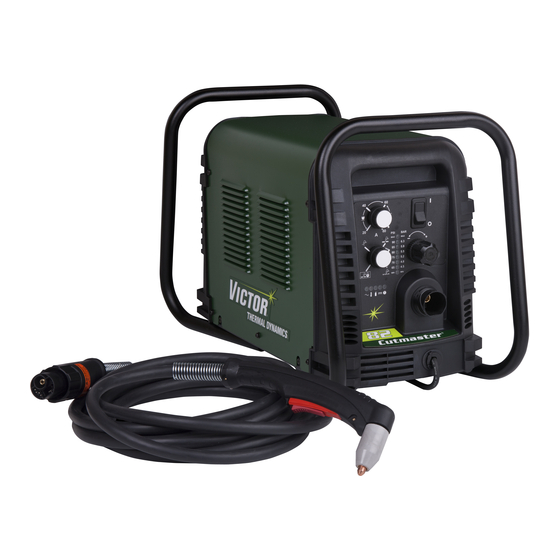
- Page 1 208- 400V 460V 600V 230V CUTMASTER ™ PLASMA CUTTING SYSTEM Operating Manual Art # A-08607_AD Revision: AR Issue Date: February 11, 2014 Manual No.: 0-4979 VictorThermalDynamics.com...
- Page 2 WE APPRECIATE YOUR BUSINESS! Congratulations on your new Victor Thermal Dynamics product. We are proud to have you as our customer and will strive to provide you with the best service and reliability in the industry. This product is backed by our extensive warranty and world-wide service network. To locate your nearest distributor or service agency call 1-800-426-1888, or visit us on the web at www.VictorThermalDynamics.com.
- Page 3 Manufacturer assumes no liability for its use. Plasma Cutting Power Supply CutMaster™ 82 SL60 1Torch™ Operating Manual Number 0-4979 Published by: Victor Technologies International, Inc. 82 Benning Street West Lebanon, New Hampshire, USA 03784 (603) 298-5711 www.victorthermaldynamics.com Copyright 2007, 2008, 2009, 2010, 2011, 2012, 2013 by Victor Technologies International, Inc.
- Page 4 This Page Intentionally Blank...
-
Page 5: Table Of Contents
TABLE OF CONTENTS SECTION 1: GENERAL INFORMATION ................1-1 1.01 Notes, Cautions and Warnings ..................1-1 1.02 Important Safety Precautions ..................1-1 1.03 Publications ........................1-2 1.04 Note, Attention et Avertissement ................1-2 1.05 Precautions De Securite Importantes .................1-3 1.06 Documents De Reference ....................1-5 1.07 Declaration of Conformity ....................1-6 1.08 Statement of Warranty ....................1-7... - Page 6 TABLE OF CONTENTS SECTION 4 TORCH: OPERATION ................4T-1 4T.01 Torch Parts Selection ....................4T-1 4T.02 Cut Quality ........................4T-2 4T.03 General Cutting Information ..................4T-2 4T.04 Hand Torch Operation ....................4T-3 4T.05 Gouging ......................... 4T-6 4T.06 Mechanized Torch Operation ..................4T-7 4T.07 Parts Selection for Manual and Mechanized Torch Cutting .......
-
Page 7: Section 1: General Information
CUTMASTER 82 SECTION 1: To prevent possible injury, read, understand and follow all warnings, safety precautions GENERAL INFORMATION and instructions before using the equipment. Call 1-603-298-5711 or your local distributor if you have any questions. 1.01 Notes, Cautions and Warnings Throughout this manual, notes, cautions, and warnings are used to highlight important information. -
Page 8: Publications
CUTMASTER 82 • Never touch any parts that are electrically “live” or “hot.” PLASMA ARC RAYS • Wear dry gloves and clothing. Insulate yourself from the work piece or other parts of the welding Plasma Arc Rays can injure your eyes and burn your circuit. -
Page 9: Note, Attention Et Avertissement
CUTMASTER 82 5. ANSI Standard Z41.1, STANDARD FOR MEN’S SAFE- TY-TOE FOOTWEAR, obtainable from the American National Standards Institute, 1430 Broadway, New York, AVERTISSEMENT NY 10018 6. ANSI Standard Z49.2, FIRE PREVENTION IN THE USE Toute procédure pouvant provoquer des bles- OF CUTTING AND WELDING PROCESSES, obtain- sures de l’opérateur ou des autres personnes... - Page 10 CUTMASTER 82 • Eloignez toute fumée et gaz de votre zone de respi- ration. Gardez votre tête hors de la plume de fumée provenant du chalumeau. CHOC ELECTRIQUE • Utilisez un appareil respiratoire à alimentation en Les chocs électriques peuvent blesser ou même tuer. Le air si l’aération fournie ne permet pas d’éliminer la...
- Page 11 CUTMASTER 82 • Utilisez la nuance de lentille qui est suggèrée dans le recommendation qui suivent ANSI/ASC Z49.1: INCENDIE ET EXPLOSION Nuance Minimum Nuance Suggerée Courant Arc Protective Numéro Numéro Les incendies et les explosions peuvent résulter des scories chaudes, des étincelles ou de l’arc de plasma. Le Moins de 300* procédé...
-
Page 12: Documents De Reference
CUTMASTER 82 1.06 Documents De Reference Consultez les normes suivantes ou les révisions les plus récentes ayant été faites à celles-ci pour de plus amples renseignements : 1. OSHA, NORMES DE SÉCURITÉ DU TRAVAIL ET DE PROTECTION DE LA SANTÉ, 29CFR 1910, disponible auprès du Superintendent of Documents, U.S. -
Page 13: Declaration Of Conformity
* CSA E60974-1: 2012 Arc Welding Equipment - Part 1: Welding Power Sources * IEC 60974-1: 2012 Arc Welding Equipment - Part 1: Welding Power Sources Victor Technologies has been manufacturing products for more than 30 years, and will continue to achieve excellence in our area of manufacture. -
Page 14: Statement Of Warranty
Victor Technologies, Inc. will honor warranty claims submitted within the warranty periods listed below. All warranty periods begin on the date of sale of the product to the original retail customer or 1 year after sale to an authorized Victor Thermal Dynamics Distributor. -
Page 15: Section 2 System: Introduction
Additional copies of this manual may be purchased by contacting Victor Technologies at the address and phone number in your area listed in the inside back cover of this manual. Include the Owner’s Manual number and equipment identification numbers. -
Page 16: Power Supply Specifications
Output Current 20 - 80 Amps, Continuously Adjustable Power Supply Gas Particulates to 5 Microns Filtering Ability CutMaster 82 Power Supply Duty Cycle * Duty Cycle Ratings @ 40° C (104° F) Ambient Temperature Operating Range 0° - 50° C Rating... -
Page 17: Input Wiring Specifications
CUTMASTER 82 2.05 Input Wiring Specifications CutMaster 82 Power Supply Input Cable Wiring Requirements Input voltage Freq Power Input Suggested Sizes Flexible Cord Volts I max Fuse (amps) (Min. AWG) 1 Phase 50/60 50/60 11.8 3 Phase 50/60 11.8 Line Voltages with Suggested Circuit Protection and Wire Sizes... -
Page 18: Power Supply Features
CUTMASTER 82 2.06 Power Supply Features Handle and Leads Wrap Control Panel Torch Leads Receptacle Art # A-07942 Work Cable and Clamp Port for Optional Automation Interface Cable Input Power Selection Filter Assembly Gas Inlet Port Art # A-07981 Input Power Cord... -
Page 19: Section 2 Torch: Introduction
CUTMASTER 82 SECTION 2 TORCH: 10.125" (257 mm) INTRODUCTION 2T.01 Scope of Manual 3.75" (95 mm) This manual contains descriptions, operating instruc- Art # A-03322_AB tions and maintenance procedures for the 1Torch Models 1.17" (29 mm) SL60/Manual and SL100/Mechanized Plasma Cut- ting Torches. -
Page 20: 04 Options And Accessories
CUTMASTER 82 F. Torch Ratings 2T.05 Introduction to Plasma Manual Torch Ratings A. Plasma Gas Flow Ambient 104° F Plasma is a gas which has been heated to an ex- Temperature 40° C tremely high temperature and ionized so that it... - Page 21 CUTMASTER 82 B. Gas Distribution E. Parts - In - Place (PIP) The single gas used is internally split into plasma The torch includes a 'Parts - In - Place' (PIP) circuit. and secondary gases. When the shield cup is properly installed, it closes a switch.
- Page 22 CUTMASTER 82 This Page Intentionally Blank INTRODUCTION Manual 0-4979 2T-4...
-
Page 23: Section 3 System: Installation
CUTMASTER 82 SECTION 3 SYSTEM: INSTALLATION 3.01 Unpacking 1. Use the packing lists to identify and account for each item. 2. Inspect each item for possible shipping damage. If damage is evident, contact your distributor and Art# A-11478 / or shipping company before proceeding with Contactor cover the installation. - Page 24 CUTMASTER 82 NOTE 7. With a little slack in the wires, tighten the through - hole protector to secure the power cable. There is only one jumper setting that changes between the single and three phase settings. 8. Reinstall the Power Supply cover per instructions To change from single phase to three phase, found in section 5.
-
Page 25: Gas Connections
CUTMASTER 82 7. With a little slack in the wires, tighten the through - hole NOTE protector to secure the power cable. For a secure seal, apply thread sealant to the fitting threads, according to the maker's in- 8. Reinstall the Power Supply cover per instructions found structions. - Page 26 CUTMASTER 82 Regulator/Filter Assembly 2-Stage Filter Inlet Port (IN) Regulator Input Outlet Port (OUT) Two Stage Filter Hose Clamp Assembly Gas Supply Hose 1/4 NPT to 1/4” (6mm) Fitting Art # A-07945_AC Optional Two - Stage Filter Installation Using High Pressure Air Cylinders When using high pressure air cylinders as the air supply: 1.
-
Page 27: Section 3 Torch: Installation
CUTMASTER 82 SECTION 3 TORCH: Check Air Quality To test the quality of air: INSTALLATION 1. Put the ON / OFF switch in the ON (up) 3T.01 Torch Connections position. If necessary, connect the torch to the Power Supply. 2. Put the Function Control switch in the SET Connect only the Thermal Dynamics model SL60 / position. - Page 28 CUTMASTER 82 Pinch Block Assembly Square Workpiece A-02585 Mechanical Torch Set - Up 3. The proper torch parts (shield cup, tip, start car- tridge, and electrode) must be installed for the type of operation. Refer to Section 4T.07, Torch Parts Selection for details.
-
Page 29: Section 4 System: Operation
CUTMASTER 82 SECTION 4 SYSTEM: OPERATION 4.01 Front Panel Controls / Features See illustration for numbering Identification 1. Output Current Control Sets the desired output current. Output settings up to 60 Amps may be used for drag cutting (with the torch tip contacting the workpiece) or higher for standoff cutting. -
Page 30: Preparations For Operation
CUTMASTER 82 Power ON 4.02 Preparations for Operation Place the Power Supply ON / OFF switch to the At the start of each operating session: ON (up) position. AC indicator turns ON. Gas indicator turns ON if there is sufficient gas... - Page 31 CUTMASTER 82 STANDOFF Typical Cutting Speeds CutMaster 82 Gas Pressure Settings Cutting speeds vary according to torch output am- Leads SL60 SL100 perage, the type of material being cut, and operator Length (Hand Torch) (Mechanized Torch) skill. Refer to Section 4T.08 and following for greater details.
- Page 32 CUTMASTER 82 This Page Intentionally Blank OPERATION Manual 0-4979...
-
Page 33: Section 4 Torch: Operation
CUTMASTER 82 SECTION 4 TORCH: OPERATION Torch Head Electrode 4T.01 Torch Parts Selection Depending on the type of operation to be done deter- mines the torch parts to be used. Start Cartridge Type of operation: Drag cutting, standoff cutting or gouging... -
Page 34: 02 Cut Quality
CUTMASTER 82 4T.02 Cut Quality Bottom Dross Buildup Molten material which is not blown out of the cut NOTE area and resolidifies on the plate. Excessive dross may require secondary cleanup operations after Cut quality depends heavily on setup and cutting. -
Page 35: 04 Hand Torch Operation
CUTMASTER 82 Edge Starting 4T.04 Hand Torch Operation For edge starts, hold the torch perpendicular to the Standoff Cutting With Hand Torch workpiece with the front of the tip near (not touch- ing) the edge of the workpiece at the point where NOTE the cut is to start. - Page 36 CUTMASTER 82 Forcing the shield cup against the torch head or torch handle can damage components. 8. For a consistent standoff height from the work- piece, install the standoff guide by sliding it onto the torch shield cup. Install the guide with the...
- Page 37 CUTMASTER 82 1. Install the drag cutting tip and set the output 8. Cut as usual. Simply release the trigger assembly current. to stop cutting. 2. The torch can be comfortably held in one hand 9. Follow normal recommended cutting practices as or steadied with two hands.
-
Page 38: 05 Gouging
CUTMASTER 82 NOTE Gouging Parameters The gas preflow and postflow are a character- Gouging performance depends on parameters istic of the power supply and not a function such as torch travel speed, current level, lead angle of the torch. (the angle between the torch and workpiece), and... -
Page 39: 06 Mechanized Torch Operation
CUTMASTER 82 Standoff Distance The tip to work distance affects gouge quality and depth. Standoff distance of 1/8 - 1/4 inch (3 - 6 mm) allows for smooth, consistent metal removal. Smaller standoff distances may result in a severance D i r cut rather than a gouge. -
Page 40: 07 Parts Selection For Manual And Mechanized Torch Cutting
NOTE CutMaster 52 uses 60A and less Tip Gouging B 9-8226 (50 - 100 Amps) CutMaster 82 uses 80A and less CutMaster 102 uses 100A and less Tip Gouging C 9-8227 (60 - 120 Amps) CutMaster 152 uses 120A and less... -
Page 41: 08 Recommended Cutting Speeds For Mechanized Torch With Exposed Tip
CUTMASTER 82 4T.08 Recommended Cutting Speeds for Mechanized Torch With Exposed Tip Type Torch: SL60 With Exposed Tip Type Material: Mild Steel Type Plasma Gas: Air Type Secondary Gas: Single Gas Torch Thickness Output Amperage Speed (Per Minute) Standoff Plasma Gas Press... - Page 42 CUTMASTER 82 Type Torch: SL60 With Exposed Tip Type Material: Mild Steel Type Plasma Gas: Air Type Secondary Gas: Single Gas Torch Thickness Output Amperage Speed (Per Minute) Standoff Plasma Gas Press Flow (CFH) Pierce Pierce Height Inches mm (Cat. No.) Volts(VDC)
- Page 43 CUTMASTER 82 Type Torch: SL60 With Exposed Tip Type Material: Mild Steel Type Plasma Gas: Air Type Secondary Gas: Single Gas Torch Thickness Output Amperage Speed (Per Minute) Standoff Plasma Gas Press Flow (CFH) Pierce Pierce Height Inches mm (Cat. No.) Volts(VDC)
-
Page 44: 09 Recommended Cutting Speeds For Mechanized Torch With Shielded Tip
CUTMASTER 82 Type Torch: SL60 with Exposed Tip Type Material: Aluminum Type Plasma Gas: Air Type Secondary Gas: Single Gas Torch Thickness Output Amperage Speed (Per Minute) Standoff Plasma Gas Press Flow (CFH) Pierce Pierce Height Inches mm (Cat. No.) Volts(VDC) - Page 45 CUTMASTER 82 Type Torch: SL60 With Shielded Tip Type Material: Aluminum Type Plasma Gas: Air Type Secondary Gas: Single Gas Torch Thickness Output Amperage Speed (Per Minute) Standoff Plasma Gas Press Flow (CFH) Pierce Pierce Height Inches (Cat. No.) Volts(VDC)
- Page 46 CUTMASTER 82 Type Torch: SL60 With Shielded Tip Type Material: Aluminum Type Plasma Gas: Air Type Secondary Gas: Single Gas Torch Thickness Output Amperage Speed (Per Minute) Standoff Plasma Gas Press Flow (CFH) Pierce Pierce Height Inches mm (Cat. No.) Volts(VDC)
- Page 47 CUTMASTER 82 Type Torch: SL60 With Shielded Tip Type Material: Stainless Steel Type Plasma Gas: Air Type Secondary Gas: Single Gas Torch Thickness Output Amperage Speed (Per Minute) Standoff Plasma Gas Press Flow (CFH) Pierce Pierce Height Inches mm (Cat. No.) Volts(VDC)
-
Page 48: Patent Information
CUTMASTER 82 PATENT INFORMATION Plasma Cutting Torch Patents The following parts are covered under U.S. and Foreign Patents as follows: Catalog # Description Patent(s) 9-8215 Electrode US Pat No(s) 6163008; 6987238 Other Pat(s) Pending 9-8213 Cartridge US Pat No(s) 6903301; 6717096; 6936786;... - Page 49 CUTMASTER 82 Catalog # Description Patent(s) 9-8245 Shield Cap US Pat No(s) 6914211; D496951 Other Pat(s) Pending The following parts are also licensed under U.S. Patent No. 5,120,930 and 5,132,512: Catalog # Description 9-8235 Shield Cap 9-8236 Shield Cap 9-8237...
- Page 50 CUTMASTER 82 This Page Intentionally Blank OPERATION Manual 0-4979 4T-18...
-
Page 51: Section 5 System: Service
CUTMASTER 82 SECTION 5 SYSTEM: SERVICE 5.01 General Maintenance Maintain more often Warning! if used under severe Disconnect input power before maintaining. conditions Each Use Visual check of torch tip and electrode Weekly Visually inspect the cables and leads. Replace as needed... -
Page 52: Maintenance Schedule
CUTMASTER 82 5.02 Maintenance Schedule 5.03 Common Faults Problem - Symptom Common Cause NOTE Insufficient 1. Cutting speed too fast. The actual frequency of maintenance may Penetration 2. Torch tilted too much. need to be adjusted according to the operat- 3. -
Page 53: Fault Indicator
CUTMASTER 82 5.04 Fault Indicator At initial power up, two lights will temporarily illumi- nate for 2-3 seconds to show the version of software used. To determine the first digit, count the function indicators left to right, 1 through 5. To determine the second digit count the pressure indicators, reading from bottom to top, 0 through 7. -
Page 54: Basic Troubleshooting Guide
CUTMASTER 82 5.05 Basic Troubleshooting Guide WARNING There are extremely dangerous voltage and power levels present inside this unit. Do not attempt to diagnose or repair unless you have had training in power electronics measurement and troubleshooting techniques. Problem - Symptom Possible Cause... - Page 55 CUTMASTER 82 Problem - Symptom Possible Cause Recommended Action FAULT & 80 PSI 1. Torch shield cup is loose. 1. Tighten shield cup by hand. Do not overtighten. indicators flashing. 2. Torch tip, electrode or starter 2. Turn OFF power supply. Remove shield cup. Install Gas flow is cycling cartridge missing.
-
Page 56: Power Supply Basic Parts Replacement
CUTMASTER 82 5.06 Power Supply Basic Parts C. Filter Element Assembly Replacement Replacement The Filter Element Assembly is in the rear panel. For better system performance, the filter element should be checked per the Maintenance Schedule (Subsection 5.02), and either cleaned or replaced. - Page 57 CUTMASTER 82 5. Remove the fitting from the filter element as- to Section 6, Parts List, for replacement filter element sembly by inserting a 6 mm hex wrench into catalog number. the internal hex fitting and turning it counter 1. Remove power from power supply.
- Page 58 CUTMASTER 82 WARNING Always turn OFF the air supply and bleed the system before disassembling the Filter Assembly as injury could result. 3. Loosen the two bolts on the top of the Filter As- sembly enough to allow the Filter Elements to move freely.
-
Page 59: Section 5 Torch: Service
CUTMASTER 82 SECTION 5 TORCH: SERVICE Upper Groove 5T.01 General Maintenance with Vent Holes Must Remain Open NOTE Upper O-Ring Refer to Previous "Section 5 System" for com- in Correct Groove mon and fault indicator descriptions. Threads Cleaning Torch Lower O-Ring... -
Page 60: 02 Inspection And Replacement Of Consumable Torch Parts
CUTMASTER 82 5T.02 Inspection and Replacement of 4. Remove the tip. Check for excessive wear (indi- cated by an elongated or oversized orifice). Clean Consumable Torch Parts or replace the tip if necessary. Worn Tip Good Tip WARNING Disconnect primary power to the system before disassembling the torch or torch leads. -
Page 61: Section 6: Parts Lists
The following items are included with the replacement power supply: work cable & clamp, input power cable, gas pressure regulator / filter, and operating manual. Description Catalog # CutMaster 82 Power Supply 208/230 - 460VAC, Single or 3 Phase, 60Hz, with input power cable and plug 3-1130-1... -
Page 62: Replacement Power Supply Parts
CUTMASTER 82 6.04 Replacement Power Supply Parts Description Catalog # Regulator 9-0115* Filter Assembly Replacement Element 9-0116 Input Power Cord for 208 / 230 V Power Supply 8-4384 Input Power Cord for 460/600 V Power Supply 9-8593 NOTE *9-0115 regulator, if the serial number of the power supply is prior to #05078755 then kit number 9-0201 will be needed to replace not only the regulator (9-0115) but the logic PCB as well. -
Page 63: Replacement Parts For Hand Torch
CUTMASTER 82 6.06 Replacement Parts for Hand Torch Item # Description Catalog # Torch Handle Replacement Kit (includes items No. 2 & 3) 9-7030 Trigger Assembly Replacement Kit 9-7034 Handle Screw Kit (5 each, 6-32 x 1/2” cap screw, and wrench) 9-8062 Torch Head Assembly Replacement Kit (includes items No. -
Page 64: Replacement Parts - For Machine Torches With Unshielded Leads
CUTMASTER 82 6.07 Replacement Parts - for Machine Torches with Unshielded Leads Item No. Qty Description Catalog No. Torch Head Assembly without leads (includes items 2, 3, and 14) 9-8220 Large O-ring 8-3487 Small O-ring 8-3486 PIP Switch Kit 9-7036 Unshielded Automated Leads Assemblies with ATC connectors 5 - foot / 1.5 m Leads Assembly with ATC connector... - Page 65 CUTMASTER 82 5 & 6 A-07994_AB Manual 0-4979 PARTS LIST...
-
Page 66: Replacement Shielded Machine Torch Leads Assemblies
CUTMASTER 82 6.08 Replacement Shielded Machine Torch Leads Assemblies Item No. Qty Description Catalog No. Mechanized Shielded Leads Assemblies with ATC Connectors 5 - foot / 1.5 m Leads Assembly with ATC Connector 4-7846 10 - foot / 3.05 m Leads Assembly with ATC Connector 4-7847 25 - foot / 7.6 m Leads Assembly with ATC Connector... -
Page 67: Torch Consumable Parts (Sl60)
Tip Gouging A 9-8225 (40 Amps Max.) NOTE CutMaster 52 uses 60A and less Tip Gouging B 9-8226 (50 - 100 Amps) CutMaster 82 uses 80A and less CutMaster 102 uses 100A and less Art # A-08065_AE Tip Gouging C 9-8227 (60 - 120 Amps) -
Page 68: Torch Consumable Parts (Sl100)
CUTMASTER 82 6.10 Torch Consumable Parts (SL100) Ohmic Clip Automation Torch Ohmic Clip 9-8224 Manual Torch 9-8259 20-40A Shield Tip: Shield Cap, Machine Cup Body, STANDOFF 40A 9-8245 9-8237 CUTTING 9-8205 Shield Cap, Deflector Shield Cup 9-8206 9-8243 9-8218 9-8208... -
Page 69: Appendix 1: Sequence Of Operation (Block Diagram
CUTMASTER 82 APPENDIX 1: SEQUENCE OF OPERATION (BLOCK DIAGRAM) ACTION: ACTION: ACTION: ACTION: RUN / Rapid Auto Restart / ON / OFF switch to ON Close external RUN / SET / LATCH disconnect switch. Rapid Auto Restart / switch to RUN... -
Page 70: Appendix 2: Data Tag Information
CUTMASTER 82 APPENDIX 2: DATA TAG INFORMATION West Lebanon, NH USA 03784 Manufacturer's Name and/or Logo, Location, Model and M odel : Revision Level, Serial Number and Production Code Dat e of M f r : Made in USA Type of Power... -
Page 71: Appendix 3: Torch Pin - Out Diagrams
CUTMASTER 82 APPENDIX 3: TORCH PIN - OUT DIAGRAMS A. Hand Torch Pin - Out Diagram ATC Female Receptacle ATC Male Connector Front View Front View Negative / Negative / Plasma Plasma 8 - Open 8 - Ground 4 - Green /... -
Page 72: Appendix 4: Torch Connection Diagrams
CUTMASTER 82 APPENDIX 4: TORCH CONNECTION DIAGRAMS A. Hand Torch Connection Diagram Torch: SL60 / SL100 Hand Torch Leads: Torch Leads with ATC Connector Power Supply: with ATC Receptacle Male ATC Female ATC Leads Connector Receptacle Power Torch Supply Torch... - Page 73 CUTMASTER 82 This Page Intentionally Blank Manual 0-4979 APPENDIX...
-
Page 74: Appendix 5: System Schematic, 208/460V Units
CUTMASTER 82 APPENDIX 5: SYSTEM SCHEMATIC, 208/460V UNITS K1-K4 K1-K4 K5, K6 K5, K6 PRI 2 PRI 2 PRI 1 PRI 1 PRI 4 PRI 4 PRI 3 PRI 3 +12VDC BIAS SUPPLY MTH2 MTH2 MTH1 MTH1 C1-C4* C1-C4* /INRUSH... - Page 75 CUTMASTER 82 CM82 / A60 ONLY 1TORCH PIP SWITCH PIP SWITCH SEC1 SEC1 SEC2 SEC2 CHOKE1 CHOKE1 +12VDC TORCH SWITCH TORCH SWITCH TEMP /OVERTEMP CIRCUIT ATC CONNECTOR AUTOMATION TORCH SOLENOID -V OUT 1 -V OUT 1 ELECTRODE1 ELECTRODE1 TIP1 TIP1...
-
Page 76: Appendix 6: System Schematic, 600V Units
CUTMASTER 82 APPENDIX 6: SYSTEM SCHEMATIC, 600V UNITS PRI 1 PRI 1 PRI 2 PRI 2 PRI 4 PRI 4 PRI 3 PRI 3 BIAS SUPPLY MTH1 MTH1 MTH2 MTH2 +12VDC + C1-C4* + C1-C4* CHOKE /INRUSH CE UNITS ONLY... - Page 77 CUTMASTER 82 1TORCH PIP SWITCH PIP SWITCH SEC1 SEC1 SEC2 SEC2 CHOKE1 CHOKE1 +12VDC TORCH SWITCH TORCH SWITCH TEMP /OVERTEMP ATC CONNECTOR CIRCUIT AUTOMATION TORCH SOLENOID -V OUT 1 -V OUT 1 ELECTRODE1 ELECTRODE1 TIP1 TIP1 PILOT IGBT PILOT IGBT...
-
Page 78: Appendix 7: Publication History
Nov. 26, 2012 Changed logo on Front Cover and Inside Front Cover from "Thermal Dynamics" to "Victor Thermal Dynamics", modified Prop 65 text Section 1, changed Catalog Number for Automation Interface Kit from 9-8310 to 9-8311 pg. 6-2; deleted items 10 &11 pg. 6-3; deleted "NOTE"... - Page 79 This Page Intentionally Blank...
- Page 80 I N N O V A T I O N T O S H A P E T H E W O R L D ™ U.S. Customer Care: 800-426-1888 / FAX 800-535-0557 Canada Customer Care: 905-827-4515 / FAX 800-588-1714 International Customer Care: 940-381-1212 / FAX 940-483-8178 Printed in Mexico © 2012 Victor Technologies International, Inc. www.victortechnologies.com...
Need help?
Do you have a question about the cutmaster 82 and is the answer not in the manual?
Questions and answers