Victor cutmaster Operating Manual
35mm
Hide thumbs
Also See for cutmaster:
- Service manual (80 pages) ,
- Operating manual (76 pages) ,
- Operating manual (80 pages)

Related Manuals for Victor cutmaster


Summary of Contents for Victor cutmaster
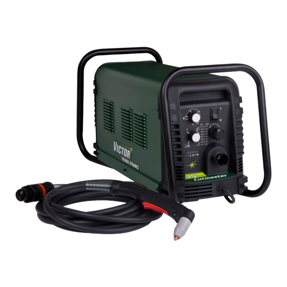
- Page 1 380/400V CUTMASTER 35 mm ® PLASMA CUTTING SYSTEM Operating Manual Revision: AJ Issue Date: February 17, 2014 Manual No.: 0-5082 VictorThermalDynamics.com...
- Page 2 WE APPRECIATE YOUR BUSINESS! Congratulations on your new Victor Thermal Dynamics product. We are proud to have you as our customer and will strive to provide you with the best service and reliability in the industry. This product is backed by our extensive warranty and world-wide service network. To locate your nearest distribu- tor or service agency call 1-800-426-1888, or visit us on the web at www.thermal-dynamics.com.
- Page 3 West Lebanon, New Hampshire, USA 03784 (603) 298-5711 www.thermal-dynamics.com Copyright 2008, 2009, 2010, 2012 by Victor Technologies International, Inc. All rights reserved. Reproduction of this work, in whole or in part, without written permission of the publisher is prohibited. The publisher does not assume and hereby disclaims any liability to any party for any loss or damage caused by any error or omission in this Manual, whether such error results from negligence, accident, or any other cause.
- Page 4 This Page Intentionally Blank...
-
Page 5: Table Of Contents
TABLE OF CONTENTS SECTION 1: GENERAL INFORMATION .....................1-1 1.01 Notes, Cautions and Warnings ..............1-1 1.02 Important Safety Precautions ..............1-1 1.03 Publications ....................1-2 1.04 Note, Attention et Avertissement ..............1-3 1.05 Precautions De Securite Importantes ............1-3 1.06 Documents De Reference ................1-6 1.07 Declaration of Conformity ................1-7 1.08 Statement of Warranty ................1-9... - Page 6 TABLE OF CONTENTS 4T.04 Hand Torch Operation ................4T-3 4T.05 Gouging ....................4T-6 4T.06 Mechanized Torch Operation ..............4T-7 4T.07 Parts Selection for SL100 Torch Cutting ..........4T-11 4T.08 Recommended Cutting Speeds for SL100 Torch With Exposed Tip ..4T-12 4T.09 Recommended Cutting Speeds for SL100 Torch With Shielded Tip ..4T-16 PATENT INFORMATION .....................4T-20 SECTION 5 SYSTEM: SERVICE .........................5-1...
-
Page 7: General Information
CUTMASTER 35MM SECTION 1: To prevent possible injury, read, understand and follow all warnings, safety precautions GENERAL INFORMATION and instructions before using the equipment. Call 1-603-298-5711 or your local distributor if you have any questions. 1.01 Notes, Cautions and Warnings Throughout this manual, notes, cautions, and warnings are used to highlight important information. -
Page 8: Publications
CUTMASTER 35MM • Never touch any parts that are electrically “live” or “hot.” PLASMA ARC RAYS • Wear dry gloves and clothing. Insulate yourself from the work piece or other parts of the welding Plasma Arc Rays can injure your eyes and burn your circuit. -
Page 9: Note, Attention Et Avertissement
CUTMASTER 35MM 4. ANSI Standard Z87.1, SAFE PRACTICES FOR OC- NOTE CUPATION AND EDUCATIONAL EYE AND FACE Toute opération, procédure ou renseigne- PROTECTION, obtainable from American National ment général sur lequel il importe d’insister Standards Institute, 1430 Broadway, New York, NY davantage ou qui contribue à... - Page 10 CUTMASTER 35MM Il faut communiquer aux opérateurs et au • Le phosgène, un gaz toxique, est généré par la fumée personnel TOUS les dangers possibles. Afin provenant des solvants et des produits de nettoyage d’éviter les blessures possibles, lisez, compre- chlorés.
- Page 11 CUTMASTER 35MM • Prévoyez une veille d’incendie lors de tout travail dans une zone présentant des dangers d’incendie. BRUIT • Le gas hydrogène peut se former ou s’accumuler sous Le bruit peut provoquer une perte permanente de l’ouïe. les pièces de travail en aluminium lorsqu’elles sont coupées sous l’eau ou sur une table d’eau.
-
Page 12: Documents De Reference
CUTMASTER 35MM 1.06 Documents De Reference Consultez les normes suivantes ou les révisions les plus récentes ayant été faites à celles-ci pour de plus amples renseignements : 1. OSHA, NORMES DE SÉCURITÉ DU TRAVAIL ET DE PROTECTION DE LA SANTÉ, 29CFR 1910, disponible auprès du Superintendent of Documents, U.S. -
Page 13: Declaration Of Conformity
• 2004/108/EC The Electromagnetic Compatibility (EMC) Directive hereby declare that Equipment: Plasma Cutting Power Source Model Name/Number: CutMaster 35MM Market Release Date: January 16,2014 is in conformity with the applicable requirements of the following harmonized standards • EN 60974-10:2007 Arc Welding Equipment - Part 10: Electromagnetic compatibility (EMC) requirements • EN 60974-1:2012 Arc Welding Equipment - Part 1: Welding power sources. - Page 14 CUTMASTER 35MM Classification: The equipment described in this manual is Class A and intended for industrial use. WARNING This Class A equipment is not intended for use in residential locations where the electrical power is provided by the public low-voltage supply system. There may be potential difficulties in ensuring electromagnetic compatibility in those locations, due to conducted as well as radiated disturbances.
-
Page 15: Statement Of Warranty
Victor Technologies, Inc. will honor warranty claims submitted within the warranty periods listed below. All warranty periods begin on the date of sale of the product to the original retail customer or 1 year after sale to an authorized Victor Thermal Dynamics Distributor. - Page 16 CUTMASTER 35MM CIGWELD Terms of Warranty - 2014 Effective 1st January 2014, all warranties against defects (also known as a manufacturer’s warranty) supplied with goods or services must comply with the mandatory requirements in the new Australian Consumer Law and the Trade Practices (Australian Consumer Law) Amendment Regulations (2010) (No.1).
-
Page 17: Section 2 System: Introduction
Electronic copies of this manual can also be downloaded at no charge in Acrobat PDF format by going to the Victor Thermal Dynamics web site listed below and clicking on Victor Thermal Dynamics and then on the Literature link: http://www.victorthermaldynamics.com... -
Page 18: Power Supply Specifications
30 - 100 Amps, Continuously Adjustable Power Supply Gas Particulates to 5 Microns Filtering Ability CutMaster 35mm Power Supply Duty Cycle * Duty Cycle Ratings @ 40° C (104° F) Ambient Temperature Operating Range 0° - 50° C Duty Cycle... -
Page 19: Input Wiring Specifications
CUTMASTER 35MM 2.05 Input Wiring Specifications CutMaster 35mm Power Supply Input Cable Wiring Requirements Input voltage Freq Power Input Suggested Sizes Fuse Flexible Cord Flexible Cord Volts I max I eff (amps) (Min. AWG) (Min. mm 18.4 Phase 18.7 Line Voltages with Suggested Circuit Protection and Wire Sizes... -
Page 20: Power Supply Features
CUTMASTER 35MM 2.06 Power Supply Features Handle and Leads Wrap Control Panel Torch Leads Receptacle Art # A-08359 Work Cable and Clamp Port for Optional Automation Interface Cable Filter Assembly Gas Inlet Port Art # A-08547 Input Power Cord INTRODUCTION... -
Page 21: Section 2 Torch: Introduction
CUTMASTER 35MM SECTION 2 TORCH: 2T.03 Specifications INTRODUCTION A. Torch Configurations 1. Hand/Manual Torch, Models 2T.01 Scope of Manual The hand torch head is at 75° to the torch handle. The hand torches include a torch handle and torch This manual contains descriptions, operating instruc- trigger assembly. -
Page 22: 04 Options And Accessories
CUTMASTER 35MM 2T.04 Options And Accessories E. Type Cooling Combination of ambient air and gas stream through For options and accessories, see section 6. torch. 2T.05 Introduction to Plasma F. Torch Ratings Manual Torch Ratings A. Plasma Gas Flow Ambient 104°... - Page 23 CUTMASTER 35MM B. Gas Distribution E. Parts - In - Place (PIP) The single gas used is internally split into plasma The torch includes a 'Parts - In - Place' (PIP) circuit. and secondary gases. When the shield cup is properly installed, it closes a switch.
- Page 24 CUTMASTER 35MM This Page Intentionally Blank 2T-4 INTRODUCTION Manual 0-5082...
-
Page 25: Section 3 System: Installation
CUTMASTER 35MM SECTION 3 SYSTEM: 3.03 Primary Input Power Connections INSTALLATION CAUTION 3.01 Unpacking Check your power source for correct voltage before plugging in or connecting the unit. 1. Use the packing lists to identify and account for The primary power source, fuse, and any each item. -
Page 26: Gas Connections
CUTMASTER 35MM Regulator/Filter Assembly CAUTION The primary power source and power cable Inlet Port must conform to local electrical code and the recommended circuit protection and wiring requirements (refer to table in Section 2). Hose Clamp 6. Connect the wires as follows. - Page 27 CUTMASTER 35MM Regulator/Filter Regulator/Filter Assembly Assembly 2-Stage Filter Inlet Port (IN) Regulator Input Outlet Port Inlet Port (OUT) Two Stage Filter Hose Clamp Assembly Gas Supply Hose Art # A-07944 1/4 NPT to 1/4” (6mm) Fitting Art # A-07945_AC Hose Clamp Optional Two - Stage Filter Installation 1/4 NPT to 1/4"...
- Page 28 CUTMASTER 35MM This Page Intentionally Blank INSTALLATION Manual 0-5082...
-
Page 29: Section 3 Torch: Installation
CUTMASTER 35MM SECTION 3 TORCH: Check Air Quality INSTALLATION To test the quality of air: 1. Put the ON / OFF switch in the ON (up) 3T.01 Torch Connections position. If necessary, connect the torch to the Power Supply. 2. Put the Function Control switch in the SET Connect only the Thermal Dynamics model SL100 / position. - Page 30 CUTMASTER 35MM Pinch Block Assembly Square Workpiece A-02585 Mechanical Torch Set - Up 3. The proper torch parts (shield cup, tip, start car- tridge, and electrode) must be installed for the type of operation. Refer to Section 4T.07, Torch Parts Selection for details.
-
Page 31: Section 4 System: Operation
CUTMASTER 35MM SECTION 4 SYSTEM: OPERATION 4.01 Front Panel Controls / Features See Illustration for numbering Identification 1. Output Current Control Sets the desired output current. Output settings up to 60 Amps may be used for drag cutting (with the torch tip contacting the workpiece) or higher for standoff cutting. -
Page 32: Preparations For Operation
CUTMASTER 35MM 10. Pressure Indicators Air Source Ensure source meets requirements (refer to Section 2). Check connections and turn air supply ON. Connect Work Cable Clamp the work cable to the workpiece or cutting table. The area must be free from oil, paint and rust. - Page 33 RUN position, there is a brief delay in restarting the pilot arc. With the knob in the RAPID AUTO STANDOFF RESTART position, when the torch leaves the work- CutMaster 35mm Gas Pressure Settings piece the pilot arc restarts instantly, and the cutting Leads SL100...
- Page 34 CUTMASTER 35MM This Page Intentionally Blank OPERATION Manual 0-5082...
-
Page 35: Section 4 Torch: Operation
CUTMASTER 35MM SECTION 4 TORCH: OPERATION Torch Head Electrode 4T.01 Torch Parts Selection Depending on the type of operation to be done deter- mines the torch parts to be used. Start Cartridge Type of operation: Drag cutting, standoff cutting or gouging... -
Page 36: 03 General Cutting Information
CUTMASTER 35MM 4T.03 General Cutting Information Kerf Width Cut Surface Bevel Angle WARNING Spatter Disconnect primary power at the source be- fore disassembling the power supply, torch, Top Edge or torch leads. Rounding Frequently review the Important Safety Pre- cautions at the front of this manual. Be sure... -
Page 37: 04 Hand Torch Operation
CUTMASTER 35MM 4T.04 Hand Torch Operation Direction of Cut In the torches, the plasma gas stream swirls as it Standoff Cutting With Hand Torch leaves the torch to maintain a smooth column of gas. This swirl effect results in one side of a cut be- NOTE ing more square than the other. - Page 38 CUTMASTER 35MM Trigger Shield Cup Standoff Guide Trigger Release Torch Tip A-02986 Workpiece Art # A-04034 5. Bring the torch within transfer distance to the work. The main arc will transfer to the work, Shield Cup With Straight Edge and the pilot arc will shut off.
- Page 39 CUTMASTER 35MM 2. The torch can be comfortably held in one hand 7. Cut as usual. Simply release the trigger assembly or steadied with two hands. Position the hand to to stop cutting. press the Trigger on the torch handle. With the 8.
-
Page 40: 05 Gouging
CUTMASTER 35MM NOTES Gouging Parameters The gas preflow and postflow are a character- Gouging performance depends on parameters istic of the power supply and not a function such as torch travel speed, current level, lead angle of the torch. (the angle between the torch and workpiece), and... -
Page 41: 06 Mechanized Torch Operation
CUTMASTER 35MM 4T.06 Mechanized Torch Operation Torch Head Cutting With Mechanized Torch The mechanized torch can be activated by remote control pendant or by a remote interface device 35° such as CNC. 1. To start a cut at the plate edge, position the center of the torch along the edge of the plate. - Page 42 CUTMASTER 35MM For optimum smooth surface quality, the travel speed should be adjusted so that only the leading edge of the arc column produces the cut. If the travel speed is too slow, a rough cut will be produced as the arc moves from side to side in search of metal for transfer.
- Page 43 CUTMASTER 35MM This Page Intentionally Blank 4T-9 Manual 0-5082 OPERATION...
- Page 44 CUTMASTER 35MM This Page Intentionally Blank 4T-10 OPERATION Manual 0-5082...
-
Page 45: 07 Parts Selection For Sl100 Torch Cutting
CUTMASTER 35MM 4T.07 Parts Selection for SL100 Torch Cutting Ohmic Clip Automation Torch Ohmic Clip 9-8224 Manual Torch 9-8259 20-40A Shield Tip: Shield Cap, Machine Cup Body, STANDOFF 40A 9-8245 9-8237 CUTTING 9-8205 Shield Cap, Deflector Shield Cup 9-8206 9-8243... -
Page 46: 08 Recommended Cutting Speeds For Sl100 Torch With Exposed Tip
CUTMASTER 35MM 4T.08 Recommended Cutting Speeds for SL100 Torch With Exposed Tip Type Torch: SL100 With Exposed Tip Type Material: Mild Steel Type Plasma Gas: Air Type Secondary Gas: Single Gas Torch Thickness Output Amperage Speed (Per Minute) Standoff Plasma Gas Press... - Page 47 CUTMASTER 35MM Type Torch: SL100 With Exposed Tip Type Material: Mild Steel Type Plasma Gas: Air Type Secondary Gas: Single Gas Torch Thickness Output Amperage Speed (Per Minute) Standoff Plasma Gas Press Flow (CFH) Pierce Pierce Height Inches mm (Cat. No.) Volts(VDC)
- Page 48 CUTMASTER 35MM Type Torch: SL100 With Exposed Tip Type Material: Mild Steel Type Plasma Gas: Air Type Secondary Gas: Single Gas Torch Thickness Output Amperage Speed (Per Minute) Standoff Plasma Gas Press Flow (CFH) Pierce Pierce Height Inches mm (Cat. No.) Volts(VDC)
- Page 49 CUTMASTER 35MM Type Torch: SL100 With Exposed Tip Type Material: Mild Steel Type Plasma Gas: Air Type Secondary Gas: Single Gas Torch Thickness Output Amperage Speed (Per Minute) Standoff Plasma Gas Press Flow (CFH) Pierce Pierce Height Inches mm (Cat. No.) Volts(VDC)
-
Page 50: 09 Recommended Cutting Speeds For Sl100 Torch With Shielded Tip
CUTMASTER 35MM 4T.09 Recommended Cutting Speeds for SL100 Torch With Shielded Tip Type Torch: SL100 With Shielded Tip Type Material: Mild Steel Type Plasma Gas: Air Type Secondary Gas: Single Gas Torch Thickness Output Amperage Speed (Per Minute) Standoff Plasma Gas Press... - Page 51 CUTMASTER 35MM Type Torch: SL100 With Shielded Tip Type Material: Mild Steel Type Plasma Gas: Air Type Secondary Gas: Single Gas Torch Thickness Output Amperage Speed (Per Minute) Standoff Plasma Gas Press Flow (CFH) Pierce Pierce Height Inches mm (Cat. No.) Volts(VDC)
- Page 52 CUTMASTER 35MM Type Torch: SL100 With Shielded Tip Type Material: Mild Steel Type Plasma Gas: Air Type Secondary Gas: Single Gas Torch Thickness Output Amperage Speed (Per Minute) Standoff Plasma Gas Press Flow (CFH) Pierce Pierce Height Inches mm (Cat. No.)
- Page 53 CUTMASTER 35MM Type Torch: SL100 With Shielded Tip Type Material: Mild Steel Type Plasma Gas: Air Type Secondary Gas: Single Gas Torch Thickness Output Amperage Speed (Per Minute) Standoff Plasma Gas Press Flow (CFH) Pierce Pierce Height Inches (Cat. No.)
-
Page 54: Patent Information
CUTMASTER 35MM PATENT INFORMATION Plasma Cutting Torch Patents The following parts are covered under U.S. and Foreign Patents as follows: Catalog # Description Patent(s) 9-8215 Electrode US Pat No(s) 6163008; 6987238 Other Pat(s) Pending 9-8213 Cartridge US Pat No(s) 6903301; 6717096; 6936786;... - Page 55 CUTMASTER 35MM Catalog # Description Patent(s) 9-8245 Shield Cap US Pat No(s) 6914211; D496951 Other Pat(s) Pending The following parts are also licensed under U.S. Patent No. 5,120,930 and 5,132,512: Catalog # Description 9-8235 Shield Cap 9-8236 Shield Cap 9-8237...
- Page 56 CUTMASTER 35MM This Page Intentionally Blank 4T-22 OPERATION Manual 0-5082...
-
Page 57: Section 5 System: Service
CUTMASTER 35MM SECTION 5 SYSTEM: SERVICE 5.01 General Maintenance Maintain more often Warning! if used under severe Disconnect input power before maintaining. conditions Each Use Visual check of torch tip and electrode Weekly Visually inspect the cables and leads. Replace as needed... -
Page 58: Maintenance Schedule
CUTMASTER 35MM 5.02 Maintenance Schedule 5.03 Common Faults NOTE Problem - Symptom Common Cause Insufficient 1. Cutting speed too fast. The actual frequency of maintenance may Penetration 2. Torch tilted too much. need to be adjusted according to the operat- 3. -
Page 59: Fault Indicator
CUTMASTER 35MM 5.04 Fault Indicator At initial power up, two lights will temporarily illumi- nate for 2-3 seconds to show the version of software used. To determine the first digit, count the function indicators left to right, 1 through 5. To determine the second digit count the pressure indicators, reading from bottom to top, 0 through 7. -
Page 60: Basic Troubleshooting Guide
CUTMASTER 35MM 5.05 Basic Troubleshooting Guide WARNING There are extremely dangerous voltage and power levels present inside this unit. Do not attempt to diagnose or repair unless you have had training in power electronics measurement and troubleshooting techniques. Problem - Symptom Possible Cause... - Page 61 CUTMASTER 35MM Problem - Symptom Possible Cause Recommended Action FAULT & 80 PSI 1. Torch shield cup is loose. 1. Tighten shield cup by hand. Do not overtighten. indicators flashing. 2. Torch tip, electrode or starter 2. Turn OFF power supply. Remove shield cup. Install missing Gas flow is cycling cartridge missing.
-
Page 62: Power Supply Basic Parts Replacement
CUTMASTER 35MM 5.06 Power Supply Basic Parts C. Filter Element Assembly Replacement Replacement The Filter Element Assembly is in the rear panel. For better system performance, the filter element should be checked per the Maintenance Schedule (Subsection 5.02), and either cleaned or replaced. - Page 63 CUTMASTER 35MM 5. Remove the fitting from the filter element as- Optional Single-Stage Filter Element sembly by inserting a 6 mm hex wrench into Replacement the internal hex fitting and turning it counter These instructions apply to power supplies where the clock-wise (left).
- Page 64 CUTMASTER 35MM Optional Two-Stage Filter Element Replacement The Two-Stage Air Filter has two Filter Elements. When the Filter Elements become dirty the Power Supply will continue to operate but cut quality may become unac- ceptable. Refer to Section 6, Parts List, for replacement filter element catalog number.
-
Page 65: Section 5 Torch: Service
CUTMASTER 35MM SECTION 5 TORCH: SERVICE Upper Groove 5T.01 General Maintenance with Vent Holes Must Remain Open NOTE Upper O-Ring Refer to Previous "Section 5 System" for com- in Correct Groove mon and fault indicator descriptions. Threads Cleaning Torch Lower O-Ring... -
Page 66: 02 Inspection And Replacement Of Consumable Torch Parts
CUTMASTER 35MM 5T.02 Inspection and Replacement of 4. Remove the tip. Check for excessive wear (indi- cated by an elongated or oversized orifice). Clean Consumable Torch Parts or replace the tip if necessary. Good Tip Worn Tip WARNING Disconnect primary power to the system before disassembling the torch or torch leads. -
Page 67: Parts Lists
/ filter, and operating manual. Description Catalog # CutMaster 35mm CE Power Supply with 400VAC, 3 phase input power cable 3-1330-4 CutMaster 35mm Non CE Power Supply with 400VAC, 3 phase input power cable 3-1330-3 6.04 Replacement Power Supply Parts Description Catalog #... -
Page 68: Options And Accessories
CUTMASTER 35MM 6.05 Options and Accessories Description Catalog # Single - Stage Filter Kit (includes Filter & Hose) 7-7507 Replacement Filter Body 9-7740 Replacement Filter Hose (not shown) 9-7742 Replacement Filter Element 9-7741 Two - Stage Filter Kit (includes Hose & Mounting Screws) - Page 69 CUTMASTER 35MM Art # A-07993_AB Manual 0-5082 PARTS LIST...
-
Page 70: Replacement Parts - For Machine Torches With Unshielded Leads
CUTMASTER 35MM 6.07 Replacement Parts - for Machine Torches with Unshielded Leads Item No. Qty Description Catalog No. Torch Head Assembly without leads (includes items 2, 3, and 14) 9-8220 Large O-Ring 8-3487 Small O-Ring 8-3486 PIP Switch Kit 9-7036 Unshielded Automated Leads Assemblies with ATC connectors 5 - foot / 1.5 m Leads Assembly with ATC connector... - Page 71 CUTMASTER 35MM 5 & 6 A-07994_AB Manual 0-5082 PARTS LIST...
-
Page 72: Replacement Shielded Machine Torch Leads Assemblies
CUTMASTER 35MM 6.08 Replacement Shielded Machine Torch Leads Assemblies Item No. Qty Description Catalog No. Mechanized Shielded Leads Assemblies with ATC Connectors 5 - foot / 1.5 m Leads Assembly with ATC Connector 4-7846 10 - foot / 3.05 m Leads Assembly with ATC Connector 4-7847 25 - foot / 7.6 m Leads Assembly with ATC Connector... -
Page 73: Torch Consumable Parts (Sl100)
CUTMASTER 35MM 6.09 Torch Consumable Parts (SL100) Ohmic Clip Automation Torch Ohmic Clip 9-8224 Manual Torch 9-8259 20-40A Shield Tip: Shield Cap, Machine Cup Body, STANDOFF 9-8237 40A 9-8245 CUTTING 9-8205 Shield Cap, Deflector Shield Cup 9-8206 9-8243 9-8218 9-8208... - Page 74 CUTMASTER 35MM This Page Intentionally Blank PARTS LIST Manual 0-5082...
-
Page 75: Appendix 1: Sequence Of Operation (Block Diagram
CUTMASTER 35MM APPENDIX 1: SEQUENCE OF OPERATION (BLOCK DIAGRAM) ACTION: ACTION: ACTION: ACTION: RUN / Rapid Auto Restart / ON / OFF switch to ON Close external RUN / SET / LATCH disconnect switch. Rapid Auto Restart / switch to RUN... -
Page 76: Appendix 2: Data Tag Information
CUTMASTER 35MM APPENDIX 2: DATA TAG INFORMATION West Lebanon, NH USA 03784 Manufacturer's Name and/or Logo, Location, Model and M odel : Revision Level, Serial Number and Production Code Dat e of M f r : Made in USA Type of Power... -
Page 77: Appendix 3: Torch Pin - Out Diagrams
CUTMASTER 35MM APPENDIX 3: TORCH PIN - OUT DIAGRAMS A. Hand Torch Pin - Out Diagram ATC Female Receptacle ATC Male Connector Front View Front View Negative / Negative / Plasma Plasma 8 - Open 8 - Ground 4 - Green /... -
Page 78: Appendix 4: Torch Connection Diagrams
CUTMASTER 35MM APPENDIX 4: TORCH CONNECTION DIAGRAMS A. Hand Torch Connection Diagram Torch: SL60 / SL100 Hand Torch Leads: Torch Leads with ATC Connector Power Supply: with ATC Receptacle Male ATC Leads ATC Female Connector Receptacle Power Torch Supply Torch... - Page 79 CUTMASTER 35MM This Page Intentionally Blank Manual 0-5082 APPENDIX...
-
Page 80: Appendix 5: System Schematic, 400V Units
CUTMASTER 35MM APPENDIX 5: SYSTEM SCHEMATIC, 400V UNITS PRI 3 PRI 3 PRI 4 PRI 4 BIAS SUPPLY PRI 2 PRI 2 PRI 2 PRI 2 INRUSH +12VDC PRI 1 PRI 1 RESISTORS PRI 1 PRI 1 MTH1 MTH1 MTH2... - Page 81 CUTMASTER 35MM 1TORCH PIP SWITCH PIP SWITCH TORCH SWITCH TORCH SWITCH SEC1 SEC1 SEC2 SEC2 CHOKE1 CHOKE1 +12VDC ATC CONNECTOR AUTOMATION TEMP /OVERTEMP TORCH SOLENOID CIRCUIT -V OUT 1 -V OUT 1 ELECTRODE1 ELECTRODE1 TIP1 TIP1 PILOT IGBT PILOT IGBT...
-
Page 82: Appendix 6: Publication History
Updated consumables art in section 4T and 6 per ECOB1819. Mar. 20, 2012 Updated ART A-08066 and changed COO text, per ECOB2149. April 25, 2012 Updated ART A-07994 per ECOB2136. No AH rev information given. Feb. 17, 2014 Implemented Victor trade dress standards. Updated DoC. ECO-B2688. APPENDIX Manual 0-5082... - Page 83 This Page Intentionally Blank...
- Page 84 I N N O V A T I O N T O S H A P E T H E W O R L D ™ U.S. Customer Care: 800-426-1888 / FAX 800-535-0557 Canada Customer Care: 905-827-4515 / FAX 800-588-1714 International Customer Care: 940-381-1212 / FAX 940-483-8178 Printed in Mexico © 2012 Victor Technologies International, Inc. www.victortechnologies.com...
Need help?
Do you have a question about the cutmaster and is the answer not in the manual?
Questions and answers