
Related Manuals for Victor CUTMASTER A80


Summary of Contents for Victor CUTMASTER A80
- Page 1 208- 380- 460V 600V 230V 400V CUTMASTER ® AUTOMATED PLASMA CUTTING SYSTEM Operating Manual Art # A-08954_AC Revision: AQ Issue Date: October 24, 2014 Manual No.: 0-4985 VictorThermalDynamics.com...
- Page 2 WE APPRECIATE YOUR BUSINESS! Congratulations on your new Victor Thermal Dynamics product. We are proud to have you as our customer and will strive to provide you with the best service and reliability in the industry. This product is backed by our extensive warranty and world-wide service network. To locate your nearest distributor or service agency call 1-800-426-1888, or visit us on the web at www.VictorThermalDynamics.com.
- Page 3 Plasma Cutting Power Supply CutMaster ® SL100 1Torch™ Operating Manual Number 0-4985 Published by: Victor Technologies International, Inc. 82 Benning Street West Lebanon, New Hampshire, USA 03784 (603) 298-5711 www.victorthermaldynamics.com Copyright 2008, 2009, 2010, 2011, 2012, 2013, 2014 by Victor Technologies International, Inc.
- Page 4 This Page Intentionally Blank...
-
Page 5: Table Of Contents
TABLE OF CONTENTS SECTION 1: GENERAL INFORMATION ..................1-1 1.01 Notes, Cautions and Warnings ..................1-1 1.02 Important Safety Precautions ..................1-1 1.03 Publications ........................1-2 1.04 Note, Attention et Avertissement ..................1-3 1.05 Precautions De Securite Importantes ................1-3 1.06 Documents De Reference ....................1-5 1.07 Declaration of Conformity .....................1-6 1.08 Statement of Warranty ....................1-7... - Page 6 TABLE OF CONTENTS 4T.09 Recommended Cutting Speeds for Machine and Automated Torches With Shielded Tip ...................... 4T-32 PATENT INFORMATION ........................ 4T-51 SECTION 5 SYSTEM: SERVICE ......................5-1 5.01 General Maintenance ....................5-1 5.02 Maintenance Schedule ....................5-2 5.03 Common Faults ......................5-2 5.04 Fault Indicator .......................5-3 5.05 Basic Troubleshooting Guide ..................5-4 5.06...
-
Page 7: Section 1: General Information
CUTMASTER A80 SECTION 1: GENERAL INFORMATION GASES AND FUMES Gases and fumes produced during the plasma cutting process can be dangerous and hazardous to your health. 1.01 Notes, Cautions and Warnings • Keep all fumes and gases from the breathing area. Keep your Throughout this manual, notes, cautions, and warnings are used to head out of the welding fume plume. -
Page 8: Publications
CUTMASTER A80 * These values apply where the actual arc is clearly seen. Experience has shown that lighter filters may be used when the arc is hidden by the workpiece. FIRE AND EXPLOSION Fire and explosion can be caused by hot slag, sparks, or the plasma arc. -
Page 9: Note, Attention Et Avertissement
CUTMASTER A80 13. NWSA booklet, WELDING SAFETY BIBLIOGRAPHY obtainable 1.05 Precautions De Securite Importantes from the National Welding Supply Association, 1900 Arch Street, Philadelphia, PA 19103 14. American Welding Society Standard AWSF4.1, RECOM- AVERTISSEMENTS MENDED SAFE PRACTICES FOR THE PREPARATION FOR WELDING AND CUTTING OF CONTAINERS AND PIPING THAT L’OPÉRATION ET LA MAINTENANCE DU MATÉRIEL DE... - Page 10 CUTMASTER A80 • Le phosgène, un gaz toxique, est généré par la fumée provenant des solvants et des produits de nettoyage chlorés. Eliminez toute source de telle fumée. RAYONS D’ARC DE PLASMA • AVERTISSEMENT: Ce produit contient des produits chimiques, Les rayons provenant de l’arc de plasma peuvent blesser vos yeux et notamment du plomb, reconnu par l'État de la Californie pour...
-
Page 11: Documents De Reference
CUTMASTER A80 1.06 Documents De Reference 14. Norme AWSF4.1 de l’Association Américaine de Soudage, RECOM- MANDATIONS DE PRATIQUES SURES POUR LA PRÉPARATION À Consultez les normes suivantes ou les révisions les plus récentes ayant LA COUPE ET AU SOUDAGE DE CONTENEURS ET TUYAUX AYANT été... -
Page 12: Declaration Of Conformity
Extensive product design verification is conducted at the manufacturing facility as part of the routine design and manufacturing process. This is to ensure the product is safe, when used according to instructions in the manual and related industry standards, and performs as specified. Rigorous testing is incorporated into the manufacturing process to ensure the manufactured product meets or exceeds all design specifications. Victor Technologies. has been manufacturing products for more than 30 years, and will continue to achieve excellence in our area of manufacture. Manufacturer’s Authorized Representative Steve Ward V.P. Europe and General Manager Address: Victor Technologies International Inc. - Page 13 CUTMASTER A80 Classification: The equipment described in this manual is Class A and intended for industrial use. WARNING This Class A equipment is not intended for use in residential locations where the electrical power is provided by the public low-voltage supply system. There may be potential difficulties in ensuring electromagnetic compatibility in those locations, due to conducted as well as radiated disturbances.
-
Page 14: Statement Of Warranty
Victor Thermal Dynamics Corporation will honor warranty claims submitted within the warranty periods listed below. All warranty periods begin on the date of sale of the product to the original retail customer or 1 year after sale to an authorized Victor Thermal Dynamics Distributor. -
Page 15: Section 2 System: Introduction
Include the Owner’s Manual number and equipment identification numbers. Electronic copies of this manual can also be downloaded at no charge in Acrobat PDF format by going to the Victor Thermal Dynamics web site listed below and clicking on Thermal Dynamics and then on the Literature link: http://www.victorthermaldynamics.com... -
Page 16: Power Supply Specifications
30 - 100 Amps, Continuously Adjustable Power Supply Gas Particulates to 5 Microns Filtering Ability CutMaster A80 Power Supply Duty Cycle * Ambient Temperature Duty Cycle Ratings @ 40° C (104° F) Operating Range 0° - 50° C All Units... -
Page 17: Input Wiring Specifications
CUTMASTER A80 2.05 Input Wiring Specifications CutMaster A80 Power Supply Input Cable Wiring Requirements Input voltage Freq Power Input Suggested Sizes Flexible Cord Flexible Cord Volts I max Fuse (amps) (Min. AWG) (Min. mm 20.6 4 Type W 25 Type W 1 Phase 21.9... -
Page 18: Power Supply Features
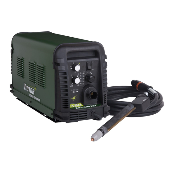
CUTMASTER A80 2.06 Power Supply Features Art # A-08460 Control Panel Torch Leads Receptacle Mounting Rails Work Cable and Clamp Automation Interface Cable Port Input Power Selection Filter Assembly Gas Inlet Port Input Power Cord Art # A-08461 Manual 0-4985... -
Page 19: Section 2 Torch: Introduction
CUTMASTER A80 SECTION 2 TORCH: 2. Machine Torch, Model INTRODUCTION The standard machine torch has a positioning tube with rack & pinch block assembly. 15.875" / 403 mm 2T.01 Scope of Manual 9.285" / 236 mm This manual contains descriptions, operating instructions and maintenance procedures for the 1Torch Models SL100/Manual 1.175"... -
Page 20: 04 Options And Accessories
CUTMASTER A80 F. Torch Ratings 2T.05 Introduction to Plasma Automated / Machine Torch Ratings A. Plasma Gas Flow Ambient 104° F Temperature 40° C Plasma is a gas which has been heated to an extremely high temperature and ionized so that it becomes electri-... - Page 21 CUTMASTER A80 B. Gas Distribution Remote Pendant The single gas used is internally split into plasma and secondary gases. The plasma gas flows into the torch through the negative PIP Switch Shield Cup lead, through the starter cartridge, around the electrode, To ATC and out through the tip orifice. The secondary gas flows down around the outside of the torch starter cartridge, and out between the tip and shield cup around the plasma arc.
- Page 22 CUTMASTER A80 This Page Intentionally Blank INTRODUCTION Manual 0-4985 2T-4...
-
Page 23: Section 3 System: Installation
CUTMASTER A80 SECTION 3 SYSTEM: 2. Place the unit in the desired position and mark where INSTALLATION the four keyway holes in the mounting rails touch. 3.01 Unpacking 3. Remove the unit and using these markings, prepare holes for mounting hardware. - Page 24 CUTMASTER A80 Most units are shipped from the factory with a 230 Volt input C. Input Power Selection power cable wired to the input contactor in the single - phase Set the Input Voltage Selection Switch at the rear of the unit configuration. The following illustrations and directions are...
-
Page 25: Gas Connections
CUTMASTER A80 4. If the power cable being used is not the factory - sup- 5. Pass the cable being used through the access opening plied cable, use a three - conductor input power cable in the back panel of the power supply. Refer to Section for the voltage desired and strip back the insulation on 2 for power cable specifications. - Page 26 CUTMASTER A80 Filter Assembly Filter Assembly Inlet Port Inlet Port Hose Clamp Gas Supply Hose Art # A-08319 Art # A-08320 Hose Clamp 1/4 NPT or ISO-R to 1/4” (6mm) Fitting 1/4 NPT to 1/4" Gas Supply Air Connection to Inlet Port...
- Page 27 CUTMASTER A80 Installing Optional Two - Stage Air Filter Kit Using High Pressure Air Cylinders This optional two - stage air line filter is also for use on When using high pressure air cylinders as the air supply: compressed air shop systems. Filter removes moisture and 1. Refer to the manufacturer’s specifications for instal-...
- Page 28 CUTMASTER A80 This Page Intentionally Blank INSTALLATION Manual 0-4985...
-
Page 29: Section 3 Torch: Installation
If necessary, connect the torch to the Power Supply. Connect 2. Put the Function Control switch in the SET posi- only the Victor Thermal Dynamics model SL100SV / Automa- tion. tion, SL100 / Mechanical or SL60 / Manual Torch to this power supply. - Page 30 CUTMASTER A80 There are three options for Divided Arc Voltage signal supplied from the automation interface pcb. This is selected by connecting the black Jumper Plug on the P1 connector as follows: Arc voltage / 16.67 Jumper not installed Arc voltage / 30 Jumper Pins 1 & 2 . This is the factory default position of the jumper Arc voltage / 50 Jumper Pins 2 &...
- Page 31 CUTMASTER A80 3T.03 Setting Up Automation or Machine Torch NOTE An adapter is required to be installed in the power supply if converting a hand torch system to operate a machine or automation torch. WARNING Disconnect primary power at the source before disassembling the torch or torch leads.
- Page 32 CUTMASTER A80 This Page Intentionally Blank INSTALLATION Manual 0-4985 3T-4...
-
Page 33: Section 4 System: Operation
CUTMASTER A80 SECTION 4 SYSTEM: OPERATION 4.01 Front Panel Controls / Features See Illustration for numbering Identification 1. Output Current Control Sets the desired output current. Output settings up to 60 Amps may be used for drag cutting (with the torch tip contacting the workpiece) or higher for standoff cutting. -
Page 34: Preparations For Operation
(10) minute period once the Torch Connection condition is cleared. Check that the torch is properly connected. Only Victor Thermal Dynamics model SL100 / Manual or SL100 / Me- Set Operating Pressure chanical Torches may be connected to this Power Supply. - Page 35 CUTMASTER A80 Cutting Operation STANDOFF CutMaster A80 Gas Pressure Settings When the torch leaves the workpiece during cutting opera- tions with the Function Control Knob in the RUN position, SL100 there is a brief delay in restarting the pilot arc. With the Leads SL100 (Mechanized Torch) knob in the RAPID AUTO RESTART position, when...
- Page 36 CUTMASTER A80 This Page Intentionally Blank OPERATION Manual 0-4985...
-
Page 37: Section 4 Torch: Operation
CUTMASTER A80 SECTION 4 TORCH: For optimum smooth surface quality, the travel speed should be adjusted so that only the leading edge of the arc OPERATION column produces the cut. If the travel speed is too slow, a rough cut will be produced as the arc moves from side to side in search of metal for transfer. -
Page 38: 03 Machine And Hand Torch Parts Selection
CUTMASTER A80 NOTE Type of operation: The shield cup holds the tip and starter cartridge in Drag cutting, standoff cutting or gouging place. Position the torch with the shield cup facing Torch parts: upward to keep these parts from falling out when the cup is removed. -
Page 39: 04 Cut Quality
CUTMASTER A80 Kerf Width 4T.04 Cut Quality The width of the cut (or the width of material removed NOTE during the cut). Cut quality depends heavily on setup and param- Top Spatter (Dross) eters such as torch standoff, alignment with the... -
Page 40: 06 Hand Torch Operation
CUTMASTER A80 Direction of Cut NOTE In the torches, the plasma gas stream swirls as it leaves The tip should never come in contact with the the torch to maintain a smooth column of gas. This swirl workpiece except during drag cutting operations. - Page 41 CUTMASTER A80 Trigger WARNING The straight edge must be non - conductive. Trigger Release Non-Conductive Straight Edge Cutting Guide A-03539 Using Drag Shield Cup With Straight Edge Art # A-03383 The crown shield cup functions best when cutting 3/16 6. Cut as usual. Simply release the trigger assembly to inch (4.7 mm) solid metal with relatively smooth surface.
- Page 42 CUTMASTER A80 NOTE The tip should never come in contact with the workpiece except during drag cutting operations. 2. Angle the torch slightly to direct blowback particles away from the torch tip (and operator) rather than Trigger directly back into it until the pierce is complete.
-
Page 43: 07 Gouging
CUTMASTER A80 Lead Angle 4T.07 Gouging The angle between the torch and workpiece depends on the output current setting and torch travel speed. The recommended lead angle is 35°. At a lead angle greater WARNING than 45° the molten metal will not be blown out of the gouge and may be blown back onto the torch. -
Page 44: 08 Recommended Cutting Speeds For Machine And Automated Torches With Exposed Tip
CUTMASTER A80 4T.08 Recommended Cutting Speeds for Machine and Automated Torches With Exposed Tip Mild Steel Air Plasma / Air Shield Starter Cartridge Standard Shield Cup Deflector Heavy Duty Starter Electrode Maximum Life Shield Cup Cartridge 9-8218 9-8213 9-8243 9-8208... - Page 45 CUTMASTER A80 Torch Material Gas Pressure Initial Piercing Kerf Width Arc Voltage Working Travel Speed Pierce Delay Thickness (Air) Height @ Rec. Speed Height (mm) (torch lead Volts (mm) (mm/min) (mm) (sec) (mm) length) 3990 2920 1810 1470 4.8 (7.6m) 1345 5.2 (15.2m)
- Page 46 CUTMASTER A80 Stainless Steel Air Plasma / Air Shield Starter Cartridge Standard Shield Cup Deflector Heavy Duty Starter Electrode Maximum Life Shield Cup Cartridge 9-8218 9-8213 9-8243 9-8208 9-8232 9-8237 9-8277 Material Gas Pressure Torch Working Initial Piercing Kerf Width Arc Voltage...
- Page 47 CUTMASTER A80 Torch Material Gas Pressure Initial Piercing Kerf Width Arc Voltage Working Travel Speed Pierce Delay Thickness (Air) Height @ Rec. Speed Height (mm) (torch lead Volts (mm) (mm/min) (mm) (sec) (mm) length) 1670 1140 5.2 (7.6) 5.5 (15.2) Edge Start BOLD TYPE indicates maximum piercing parameters.
- Page 48 CUTMASTER A80 Aluminum Air Plasma / Air Shield Starter Cartridge Standard Shield Cup Deflector Heavy Duty Starter Electrode Maximum Life Shield Cup Cartridge 9-8218 9-8213 9-8243 9-8208 9-8232 9-8237 9-8277 Material Gas Pressure Torch Working Initial Piercing Kerf Width Arc Voltage...
- Page 49 CUTMASTER A80 Torch Material Gas Pressure Initial Piercing Kerf Width Arc Voltage Working Travel Speed Pierce Delay Thickness (Air) Height @ Rec. Speed Height (mm) (torch lead Volts (mm) (mm/min) (mm) (sec) (mm) length) 7620 3500 2350 4.8 (7.6m) 2170 1740 5.2 (15.2m)
- Page 50 CUTMASTER A80 Mild Steel Air Plasma / Air Shield Starter Cartridge Standard Shield Cup Deflector Heavy Duty Starter Electrode Maximum Life Shield Cup Cartridge 9-8218 9-8213 9-8243 9-8210 9-8232 9-8237 9-8277 Material Gas Pressure Torch Working Initial Piercing Kerf Width Arc Voltage...
- Page 51 CUTMASTER A80 Torch Material Gas Pressure Initial Piercing Kerf Width Arc Voltage Working Travel Speed Pierce Delay Thickness (Air) Height @ Rec. Speed Height (mm) (torch lead Volts (mm) (mm/min) (mm) (sec) (mm) length) 7540 7015 0.10 4570 0.10 3650 0.20 2465 0.20...
- Page 52 CUTMASTER A80 Stainless Steel Air Plasma / Air Shield Starter Cartridge Standard Shield Cup Deflector Heavy Duty Starter Electrode Maximum Life Shield Cup Cartridge 9-8218 9-8213 9-8243 9-8210 9-8232 9-8237 9-8277 Material Gas Pressure Torch Working Initial Piercing Kerf Width Arc Voltage...
- Page 53 CUTMASTER A80 Torch Material Gas Pressure Initial Piercing Kerf Width Arc Voltage Working Travel Speed Pierce Delay Thickness (Air) Height @ Rec. Speed Height (mm) (torch lead Volts (mm) (mm/min) (mm) (sec) (mm) length) 10890 0.00 7560 0.10 4365 0.10 2865 0.20...
- Page 54 CUTMASTER A80 Aluminum Air Plasma / Air Shield Starter Cartridge Standard Shield Cup Deflector Heavy Duty Starter Electrode Maximum Life Shield Cup Cartridge 9-8218 9-8213 9-8243 9-8210 9-8232 9-8237 9-8277 Material Gas Pressure Torch Working Initial Piercing Kerf Width Arc Voltage...
- Page 55 CUTMASTER A80 Torch Material Gas Pressure Initial Piercing Kerf Width Arc Voltage Working Travel Speed Pierce Delay Thickness (Air) Height @ Rec. Speed Height (mm) (torch lead Volts (mm) (mm/min) (mm) (sec) (mm) length) 17010 0.00 7680 0.10 6410 0.10 5230 0.20...
- Page 56 CUTMASTER A80 Mild Steel Air Plasma / Air Shield Starter Cartridge Standard Shield Cup Deflector Heavy Duty Starter Electrode Maximum Life Shield Cup Cartridge 9-8218 9-8213 9-8243 9-8211 9-8232 9-8237 9-8277 Material Gas Pressure Torch Working Initial Piercing Kerf Width Arc Voltage...
- Page 57 CUTMASTER A80 Torch Material Gas Pressure Initial Piercing Kerf Width Arc Voltage Working Travel Speed Pierce Delay Thickness (Air) Height @ Rec. Speed Height (mm) (torch lead Volts (mm) (mm/min) (mm) (sec) (mm) length) 0.00 8915 7415 0.10 5915 0.10 4095 0.30...
- Page 58 CUTMASTER A80 Stainless Steel Air Plasma / Air Shield Starter Cartridge Standard Shield Cup Deflector Heavy Duty Starter Electrode Maximum Life Shield Cup Cartridge 9-8218 9-8213 9-8243 9-8211 9-8232 9-8237 9-8277 Material Gas Pressure Torch Working Initial Piercing Kerf Width Arc Voltage...
- Page 59 CUTMASTER A80 Torch Material Gas Pressure Initial Piercing Kerf Width Arc Voltage Working Travel Speed Pierce Delay Thickness (Air) Height @ Rec. Speed Height (mm) (torch lead Volts (mm) (mm/min) (mm) (sec) (mm) length) 9020 0.00 8380 0.00 7730 0.10 5865 0.20...
- Page 60 CUTMASTER A80 Aluminum Air Plasma / Air Shield Starter Cartridge Standard Shield Cup Deflector Heavy Duty Starter Electrode Maximum Life Shield Cup Cartridge 9-8213 9-8218 9-8243 9-8211 9-8232 9-8237 9-8277 Material Gas Pressure Torch Working Initial Piercing Kerf Width Arc Voltage...
- Page 61 CUTMASTER A80 Torch Material Gas Pressure Initial Piercing Kerf Width Arc Voltage Working Travel Speed Pierce Delay Thickness (Air) Height @ Rec. Speed Height (mm) (torch lead Volts (mm) (mm/min) (mm) (sec) (mm) length) 0.00 8890 8420 0.00 0.10 7170 5710 0.20...
- Page 62 CUTMASTER A80 Mild Steel 100A Air Plasma / Air Shield Starter Cartridge Standard Shield Cup Deflector Heavy Duty Starter Electrode Maximum Life Shield Cup Cartridge 9-8218 9-8213 9-8243 9-8212 9-8232 9-8237 9-8277 Material Gas Pressure Torch Working Initial Piercing Kerf Width...
- Page 63 CUTMASTER A80 Torch Material Gas Pressure Initial Piercing Kerf Width Arc Voltage Working Travel Speed Pierce Delay Thickness (Air) Height @ Rec. Speed Height (mm) (torch lead Volts (mm) (mm/min) (mm) (sec) (mm) length) 2200 0.10 2030 0.10 1790 0.20 5.2 (7.6m) 1310 0.40...
- Page 64 CUTMASTER A80 Stainless Steel 100A Air Plasma / Air Shield Starter Cartridge Standard Shield Cup Deflector Heavy Duty Starter Electrode Maximum Life Shield Cup Cartridge 9-8218 9-8213 9-8243 9-8212 9-8232 9-8237 9-8277 Material Gas Pressure Torch Working Initial Piercing Kerf Width...
- Page 65 CUTMASTER A80 Torch Material Gas Pressure Initial Piercing Kerf Width Arc Voltage Working Travel Speed Pierce Delay Thickness (Air) Height @ Rec. Speed Height (mm) (torch lead Volts (mm) (mm/min) (mm) (sec) (mm) length) 2630 0.00 2080 0.10 1575 0.20 5.2 (7.6m) 1255 0.30...
- Page 66 CUTMASTER A80 Aluminum 100A Air Plasma / Air Shield Starter Cartridge Standard Shield Cup Deflector Heavy Duty Starter Electrode Maximum Life Shield Cup Cartridge 9-8218 9-8213 9-8243 9-8212 9-8232 9-8237 9-8277 Material Gas Pressure Torch Working Initial Piercing Kerf Width Arc Voltage...
- Page 67 CUTMASTER A80 Torch Material Gas Pressure Initial Piercing Kerf Width Arc Voltage Working Travel Speed Pierce Delay Thickness (Air) Height @ Rec. Speed Height (mm) (torch lead Volts (mm) (mm/min) (mm) (sec) (mm) length) 2630 0.00 2080 0.10 1575 0.20 5.2 (7.6m) 1255 0.30...
-
Page 68: 09 Recommended Cutting Speeds For Machine And Automated Torches With Shielded Tip
CUTMASTER A80 4T.09 Recommended Cutting Speeds for Machine and Automated Torches With Shielded Tip Mild Steel Air Plasma / Air Shield Starter Cartridge Shield Cap Maximum Life Shield Cup Heavy Duty Starter Electrode Cartridge 9-8213 9-8245 9-8237 9-8208 9-8232 9-8277... - Page 69 CUTMASTER A80 Torch Material Gas Pressure Initial Piercing Kerf Width Arc Voltage Working Travel Speed Pierce Delay Thickness (Air) Height @ Rec. Speed Height (mm) (torch lead Volts (mm) (mm/min) (mm) (sec) (mm) length) 3266 2239 1794 1651 5.2 (7.6) 1578 5.5 (15.2)
- Page 70 CUTMASTER A80 Stainless Steel Air Plasma / Air Shield Starter Cartridge Shield Cap Maximum Life Shield Cup Heavy Duty Starter Electrode Cartridge 9-8213 9-8245 9-8237 9-8208 9-8232 9-8277 Material Gas Pressure Torch Working Initial Piercing Kerf Width Arc Voltage Travel Speed...
- Page 71 CUTMASTER A80 Torch Material Gas Pressure Initial Piercing Kerf Width Arc Voltage Working Travel Speed Pierce Delay Thickness (Air) Height @ Rec. Speed Height Bar (torch lead (mm) Volts (mm) (mm/min) (mm) (sec) (mm) length) 1670 1140 5.2 (7.6) 5.5 (15.2) BOLD TYPE indicates maximum piercing parameters.
- Page 72 CUTMASTER A80 Aluminum Air Plasma / Air Shield Starter Cartridge Shield Cap Maximum Life Shield Cup Heavy Duty Starter Electrode Cartridge 9-8213 9-8245 9-8237 9-8208 9-8232 9-8277 Material Gas Pressure Torch Working Initial Piercing Kerf Width Arc Voltage Travel Speed Pierce Delay...
- Page 73 CUTMASTER A80 Torch Material Gas Pressure Initial Piercing Kerf Width Arc Voltage Working Travel Speed Pierce Delay Thickness (Air) Height @ Rec. Speed Height (mm) (torch lead Volts (mm) (mm/min) (mm) (sec) (mm) length) 7660 3490 2350 5.2 (7.6) 2170 1630 5.5 (15.2)
- Page 74 CUTMASTER A80 Mild Steel Air Plasma / Air Shield Starter Cartridge Shield Cap Maximum Life Shield Cup Heavy Duty Starter Electrode Cartridge 9-8213 9-8238 9-8237 9-8210 9-8232 9-8277 Gas Pressure Material Torch Working Initial Piercing Kerf Width Arc Voltage Travel Speed...
- Page 75 CUTMASTER A80 Torch Material Gas Pressure Initial Piercing Kerf Width Arc Voltage Working Travel Speed Pierce Delay Thickness (Air) Height @ Rec. Speed Height (mm) (torch lead Volts (mm) (mm/min) (mm) (sec) (mm) length) 6804 5942 0.10 5080 0.10 3316 0.20 2794 0.20...
- Page 76 CUTMASTER A80 Stainless Steel Air Plasma / Air Shield Starter Cartridge Shield Cap Maximum Life Shield Cup Heavy Duty Starter Electrode Cartridge 9-8213 9-8238 9-8237 9-8210 9-8232 9-8277 Material Gas Pressure Torch Working Initial Piercing Kerf Width Arc Voltage Travel Speed...
- Page 77 CUTMASTER A80 Torch Material Gas Pressure Initial Piercing Kerf Width Arc Voltage Working Travel Speed Pierce Delay Thickness (Air) Height @ Rec. Speed Height (mm) (torch lead Volts (mm) (mm/min) (mm) (sec) (mm) length) 4590 0.00 3925 0.10 3285 0.10 1985 0.20...
- Page 78 CUTMASTER A80 Aluminum Air Plasma / Air Shield Starter Cartridge Shield Cap Maximum Life Shield Cup Heavy Duty Starter Electrode Cartridge 9-8213 9-8238 9-8237 9-8210 9-8232 9-8277 Gas Pressure Material Torch Working Initial Piercing Kerf Width Arc Voltage Travel Speed Pierce Delay...
- Page 79 CUTMASTER A80 Torch Material Gas Pressure Initial Piercing Kerf Width Arc Voltage Working Travel Speed Pierce Delay Thickness (Air) Height @ Rec. Speed Height (mm) (torch lead Volts (mm) (mm/min) (mm) (sec) (mm) length) 8890 0.00 8890 0.10 7070 0.10 5095 0.20...
- Page 80 CUTMASTER A80 Mild Steel Air Plasma / Air Shield Starter Cartridge Shield Cap Maximum Life Shield Cup Heavy Duty Starter Electrode Cartridge 9-8213 9-8239 9-8237 9-8211 9-8232 9-8277 Torch Gas Pressure Material Initial Piercing Kerf Width Arc Voltage Working Travel Speed...
- Page 81 CUTMASTER A80 Torch Material Gas Pressure Initial Piercing Kerf Width Arc Voltage Working Travel Speed Pierce Delay Thickness (Air) Height @ Rec. Speed Height (mm) (torch lead Volts (mm) (mm/min) (mm) (sec) (mm) length) 0.00 7895 6395 0.10 4895 0.10 4025 0.30...
- Page 82 CUTMASTER A80 Stainless Steel Air Plasma / Air Shield Starter Cartridge Shield Cap Maximum Life Shield Cup Heavy Duty Starter Electrode Cartridge 9-8213 9-8239 9-8237 9-8211 9-8232 9-8277 Torch Gas Pressure Material Initial Piercing Kerf Width Arc Voltage Working Travel Speed...
- Page 83 CUTMASTER A80 Torch Material Gas Pressure Initial Piercing Kerf Width Arc Voltage Working Travel Speed Pierce Delay Thickness (Air) Height @ Rec. Speed Height (mm) (torch lead Volts (mm) (mm/min) (mm) (sec) (mm) length) 0.00 9410 8120 0.00 6830 0.10 5635 0.20...
- Page 84 CUTMASTER A80 Aluminum Air Plasma / Air Shield Starter Cartridge Shield Cap Maximum Life Shield Cup Heavy Duty Starter Electrode Cartridge 9-8213 9-8239 9-8237 9-8211 9-8232 9-8277 Torch Gas Pressure Material Initial Piercing Kerf Width Arc Voltage Working Travel Speed Pierce Delay...
- Page 85 CUTMASTER A80 Torch Material Gas Pressure Initial Piercing Kerf Width Arc Voltage Working Travel Speed Pierce Delay Thickness (Air) Height @ Rec. Speed Height (mm) (torch lead Volts (mm) (mm/min) (mm) (sec) (mm) length) 0.00 9020 0.00 7595 0.10 6165 0.20 5045 5.9 (7.6m)
- Page 86 CUTMASTER A80 Mild Steel 100A Air Plasma / Air Shield Starter Cartridge Shield Cap Maximum Life Shield Cup Heavy Duty Starter Electrode Cartridge 9-8213 9-8239 9-8237 9-8233 9-8232 9-8277 Material Gas Pressure Torch Working Initial Piercing Kerf Width Arc Voltage Travel Speed...
- Page 87 CUTMASTER A80 Torch Material Gas Pressure Initial Piercing Kerf Width Arc Voltage Working Travel Speed Pierce Delay Thickness (Air) Height @ Rec. Speed Height (mm) (torch lead Volts (mm) (mm/min) (mm) (sec) (mm) length) 0.00 2210 1960 0.10 1665 0.20 1185 0.30...
- Page 88 CUTMASTER A80 Stainless Steel 100A Air Plasma / Air Shield Starter Cartridge Shield Cap Maximum Life Shield Cup Heavy Duty Starter Electrode Cartridge 9-8213 9-8239 9-8237 9-8212 9-8232 9-8277 Material Gas Pressure Torch Working Initial Piercing Kerf Width Arc Voltage Travel Speed...
- Page 89 CUTMASTER A80 Torch Material Gas Pressure Initial Piercing Kerf Width Arc Voltage Working Travel Speed Pierce Delay Thickness (Air) Height @ Rec. Speed Height (mm) (torch lead Volts (mm) (mm/min) (mm) (sec) (mm) length) 0.00 2900 2265 0.10 1685 0.20 5.2 (7.6m) 1285 0.30...
- Page 90 CUTMASTER A80 Aluminum 100A Air Plasma / Air Shield Starter Cartridge Shield Cap Maximum Life Shield Cup Heavy Duty Starter Electrode Cartridge 9-8213 9-8239 9-8237 9-8212 9-8232 9-8277 Gas Pressure Material Torch Working Initial Piercing Kerf Width Arc Voltage Travel Speed...
- Page 91 CUTMASTER A80 Torch Material Gas Pressure Initial Piercing Kerf Width Arc Voltage Working Travel Speed Pierce Delay Thickness (Air) Height @ Rec. Speed Height (mm) (torch lead Volts (mm) (mm/min) (mm) (sec) (mm) length) 0.00 2920 2135 0.10 1470 0.20 5.2 (7.6m) 1230 0.30...
-
Page 92: Patent Information
CUTMASTER A80 PATENT INFORMATION Plasma Cutting Torch Patents The following parts are covered under U.S. and Foreign Patents as follows: Catalog # Description Patent(s) 9-8215 Electrode US Pat No(s) 6163008; 6987238 Other Pat(s) Pending 9-8232 Electrode US Pat No(s) 6163008; 6987238... - Page 93 CUTMASTER A80 Catalog # Description Patent(s) 9-8239 Shield Cap US Pat No(s) 6914211; D496951 Other Pat(s) Pending 9-8244 Shield Cap US Pat No(s) 6914211; D505309 Other Pat(s) Pending 9-8245 Shield Cap US Pat No(s) 6914211; D496951 Other Pat(s) Pending The following parts are also licensed under U.S. Patent No. 5,120,930 and 5,132,512:...
- Page 94 CUTMASTER A80 This Page Intentionally Blank OPERATION Manual 0-4985 4T-58...
-
Page 95: Section 5 System: Service
CUTMASTER A80 SECTION 5 SYSTEM: SERVICE 5.01 General Maintenance Maintain more often Warning! if used under severe Disconnect input power before maintaining. conditions Each Use Visual check of torch tip and electrode Weekly Visually inspect the cables and leads. Replace as needed... -
Page 96: Maintenance Schedule
3. Metal too thick. 4. Worn torch parts 5. Cutting current too low. Daily Operational Checks or Every Six Cutting 6. Non - Genuine Victor Thermal Hours: Dynamics parts used 1. Check torch consumable parts, replace if damaged or 7. Incorrect gas pressure worn. -
Page 97: Fault Indicator
CUTMASTER A80 5.04 Fault Indicator At initial power up, two lights will temporarily illuminate for 2-3 seconds to show the version of software used. To determine the first digit, count the function indicators left to right, 1 through 5. To determine the second digit count the pressure indicators, reading from bottom to top, 0 through 7. -
Page 98: Basic Troubleshooting Guide
CUTMASTER A80 5.05 Basic Troubleshooting Guide WARNING There are extremely dangerous voltage and power levels present inside this unit. Do not attempt to diagnose or repair unless you have had training in power electronics measurement and troubleshooting techniques. Problem - Symptom Possible Cause... - Page 99 CUTMASTER A80 Problem - Symptom Possible Cause Recommended Action FAULT & 80 PSI 1. Torch shield cup is loose. 1. Tighten shield cup by hand. Do not overtighten. indicators flashing. 2. Torch tip, electrode or starter 2. Turn OFF power supply. Remove shield cup. Install Gas flow is cycling cartridge missing.
-
Page 100: Power Supply Basic Parts Replacement
CUTMASTER A80 C. Filter Element Assembly Replacement 5.06 Power Supply Basic Parts Replacement The Filter Element Assembly is in the rear panel. For better system performance, the filter element should be checked per the Maintenance Schedule (Subsection 5.02), and either WARNING cleaned or replaced. - Page 101 CUTMASTER A80 5. Remove the fitting from the filter element assembly Optional Single-Stage Filter Element Replacement by inserting a 6 mm hex wrench into the internal hex These instructions apply to power supplies where the optional fitting and turning it counter clock-wise (left). Numbers Single-Stage Filter has been installed.
- Page 102 CUTMASTER A80 Optional Two-Stage Filter Element Replacement The Two-Stage Air Filter has two Filter Elements. When the Filter Elements become dirty the Power Supply will continue to oper- ate but cut quality may become unacceptable. Refer to Section 6, Parts List, for replacement filter element catalog number. 1. Shut OFF primary input power.
-
Page 103: Section 5 Torch: Service
CUTMASTER A80 SECTION 5 TORCH: SERVICE Upper Groove 5T.01 General Maintenance with Vent Holes Must Remain Open NOTE Refer to Previous "Section 5 System" for common Upper O-Ring in Correct Groove and fault indicator descriptions. Threads Cleaning Torch Lower O-Ring... -
Page 104: 02 Inspection And Replacement Of Consumable Torch Parts
CUTMASTER A80 4. Remove the tip. Check for excessive wear (indicated 5T.02 Inspection and Replacement of by an elongated or oversized orifice). Clean or replace Consumable Torch Parts the tip if necessary. Worn Tip Good Tip WARNING Disconnect primary power to the system before disassembling the torch or torch leads. -
Page 105: Section 6: Parts Lists
208/230 single phase input power cable and plug 3-1334-1 with 460V single phase input power cable 3-1334-2 CutMaster A80 Non CE Power Supply with 400VAC, 3 phase input power cable 3-1334-3 CutMaster A80 CE Power Supply with 400VAC, 3 phase input power cable... -
Page 106: Replacement Power Supply Parts
CUTMASTER A80 6.04 Replacement Power Supply Parts Description Catalog # Regulator 9-0115 Filter Assembly Replacement Element 9-0116 Input Power Cord for 208 / 230 V Power Supply 8-4384 Input Power Cord for 400 V Power Supply 9-0216 6.05 Options and Accessories... - Page 107 CUTMASTER A80 This Page Intentionally Blank Manual 0-4985 PARTS LIST...
-
Page 108: Torch Replacement Parts Sl100Sv Torch (With Solenoid On Mounting Tube)
CUTMASTER A80 6.06 Torch Replacement Parts SL100SV Torch (with Solenoid on Mounting Tube) Item No. Description Catalog No. Torch Head Assembly without leads (includes items 2, 3, and 14) 9-8220 Large O-ring 8-3487 Small O-ring 8-3486 PIP Switch Kit 9-7036 PIP Plunger and Return Spring Kit 9-7045 Automated Leads Assemblies with ATC connectors 25 - foot / 7.6 m Leads Assembly with ATC connector... - Page 109 CUTMASTER A80 Art # A-07113 Manual 0-4985 PARTS LIST...
-
Page 110: Torch Consumable Parts (Sl100 Sv)
CUTMASTER A80 6.07 Torch Consumable Parts (SL100 SV) Ohmic Clip Automation Torch Ohmic Clip 9-8224 Manual Torch 9-8259 20-40A Shield Tip: Shield Cap, Machine Cup Body, STANDOFF 40A 9-8245 9-8237 CUTTING 9-8205 Shield Cap, Deflector Shield Cup 9-8206 9-8243 9-8218... -
Page 111: Replacement Parts For Hand Torch
CUTMASTER A80 6.08 Replacement Parts for Hand Torch Item # Description Catalog # Torch Handle Replacement Kit (includes items No. 2 & 3) 9-7030 Trigger Assembly Replacement Kit 9-7034 Handle Screw Kit (5 each, 6-32 x 1/2” cap screw, and wrench) 9-8062 Torch Head Assembly Replacement Kit (includes items No. 5 & 6) 9-8219 Large O-ring 8-3487 Small O-ring 8-3486 Leads Assemblies with ATC connectors (includes switch assemblies) SL100, 20 - foot Leads Assembly with ATC connector... - Page 112 CUTMASTER A80 This Page Intentionally Blank PARTS LIST Manual 0-4985...
-
Page 113: Appendix 1: Sequence Of Operation (Block Diagram
CUTMASTER A80 APPENDIX 1: SEQUENCE OF OPERATION (BLOCK DIAGRAM) ACTION: ACTION: ACTION: ACTION: RUN / Rapid Auto Restart / ON / OFF switch to ON Close external RUN / SET / LATCH disconnect switch. Rapid Auto Restart / switch to RUN... -
Page 114: Appendix 2: Data Tag Information
CUTMASTER A80 APPENDIX 2: DATA TAG INFORMATION West Lebanon, NH USA 03784 Manufacturer's Name and/or Logo, Location, Model and Revision Level, Serial Number M odel : and Production Code Dat e of M f r : Made in USA Type of Power... -
Page 115: Appendix 3: Torch Pin - Out Diagrams
CUTMASTER A80 APPENDIX 3: TORCH PIN - OUT DIAGRAMS A. Hand Torch Pin - Out Diagram ATC Female Receptacle ATC Male Connector Front View Front View Negative / Negative / Plasma Plasma 8 - Open 8 - Ground 4 - Green /... -
Page 116: Appendix 4: Torch Connection Diagrams
CUTMASTER A80 APPENDIX 4: TORCH CONNECTION DIAGRAMS A. Hand Torch Connection Diagram Torch: SL60 / SL100 Hand Torch Leads: Torch Leads with ATC Connector Power Supply: with ATC Receptacle Male ATC Leads ATC Female Power Connector Receptacle Torch Torch Supply... - Page 117 CUTMASTER A80 This Page Intentionally Blank Manual 0-4985 APPENDIX...
-
Page 118: Appendix 5: System Schematic, 208/460V Units
CUTMASTER A80 APPENDIX 5: SYSTEM SCHEMATIC, 208/460V UNITS PRI 4 PRI 4 PRI 3 PRI 3 BIAS SUPPLY PRI 2 PRI 2 PRI 2 PRI 2 INRUSH +12VDC RESISTORS PRI 1 PRI 1 PRI 1 PRI 1 MTH1 MTH1 MTH2... - Page 119 CUTMASTER A80 A120 ONLY 1TORCH PIP SWITCH PIP SWITCH TORCH SWITCH TORCH SWITCH SEC1 SEC1 SEC2 SEC2 CHOKE1 CHOKE1 +12VDC ATC CONNECTOR AUTOMATION TEMP /OVERTEMP TORCH SOLENOID CIRCUIT -V OUT 1 -V OUT 1 ELECTRODE1 ELECTRODE1 TIP1 TIP1 PILOT IGBT...
-
Page 120: Appendix 6: System Schematic, 400V/600V Units
CUTMASTER A80 APPENDIX 6: SYSTEM SCHEMATIC, 400V/600V UNITS PRI 4 PRI 4 PRI 3 PRI 3 BIAS SUPPLY PRI 2 PRI 2 PRI 2 PRI 2 INRUSH +12VDC RESISTORS PRI 1 PRI 1 PRI 1 PRI 1 MTH1 MTH1 MTH2... - Page 121 CUTMASTER A80 1TORCH PIP SWITCH PIP SWITCH TORCH SWITCH TORCH SWITCH SEC1 SEC1 SEC2 SEC2 CHOKE1 CHOKE1 +12VDC ATC CONNECTOR AUTOMATION TEMP /OVERTEMP TORCH SOLENOID CIRCUIT -V OUT 1 -V OUT 1 ELECTRODE1 ELECTRODE1 TIP1 TIP1 PILOT IGBT PILOT IGBT...
-
Page 122: Appendix 7: Raw Arc Voltage
CUTMASTER A80 APPENDIX 7: RAW ARC VOLTAGE If raw arc voltage is necessary for the torch height control, the customer must supply an 18 AWG (1.0 mm2), single pair, unshielded cable rated for 300V or greater. All work must be performed following applicable local and national codes. - Page 123 CUTMASTER A80 Art # A-10288 Work1 (+) Polarity -V out (-) Polarity 5. Tighten the strain relief. 6. Replace the cover. 7. Connect the cable to negative and positive of Torch Height Control. Manual 0-4985 APPENDIX A-11...
-
Page 124: Appendix 8: Publication History
Add Heavy Duty Starter Cartridge 80×144(9-8277) to automated 1 Torch per ECo-B2305. Dec. 3, 2013 Updated Declaration of Conformity. Made the following rebranding changes: updated cover to show new Victor Thermal Dynamics trade dress, updated thank you text, changed headers and footers, updated rear cover. Oct. 24, 2014... - Page 125 This Page Intentionally Blank...
- Page 126 I N N O V A T I O N T O S H A P E T H E W O R L D ™ U.S. Customer Care: 800-426-1888 / FAX 800-535-0557 Canada Customer Care: 905-827-4515 / FAX 800-588-1714 International Customer Care: 940-381-1212 / FAX 940-483-8178 Printed in Mexico © 2012 Victor Technologies International, Inc. www.victortechnologies.com...
Need help?
Do you have a question about the CUTMASTER A80 and is the answer not in the manual?
Questions and answers