Table of Contents
Advertisement
Quick Links
Download this manual
See also:
Operating Manual
Advertisement
Table of Contents

Subscribe to Our Youtube Channel
Related Manuals for Victor CUTMASTER A40


Summary of Contents for Victor CUTMASTER A40
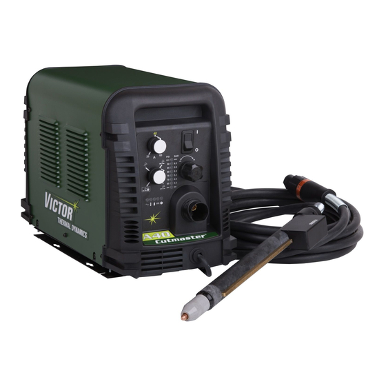
- Page 1 DUTY CYCLE 40 60 CUTMASTER A40, A60 ™ PLASMA CUTTING SYSTEM Operating Manual Revision: AJ Issue Date: April 7, 2014 Manual No.: 0-5120 VictorThermalDynamics.com...
- Page 2 WE APPRECIATE YOUR BUSINESS! Congratulations on your new Victor Thermal Dynamics product. We are proud to have you as our customer and will strive to provide you with the best service and reliability in the industry. This product is backed by our extensive warranty and world-wide service network. To locate your nearest distributor or service agency call 1-800-426-1888, or visit us on the web at www.
- Page 3 Manufacturer assumes no liability for its use. Plasma Cutting Power Supply CutMaster™ A40 SL100SV Torch™ Operating Manual No.: 0-5120 CutMaster™ A60 SL100SV Torch™ Operating Manual No.: 0-5120 Published by: Victor Technologies International, Inc. 82 Benning Street West Lebanon, New Hampshire, USA 03784 (603) 298-5711 www.victorthermaldynamics.com Copyright 2008, 2009, 2010, 2011, 2012 by Victor Technologies International, Inc.
-
Page 4: Table Of Contents
TABLE OF CONTENTS SECTION 1: GENERAL INFORMATION....................1-1 1.01 Notes, Cautions and Warnings ................1-1 1.02 Important Safety Precautions ................1-1 1.03 Publications ......................1-2 1.04 Note, Attention et Avertissement ................1-3 1.05 Precautions De Securite Importantes ..............1-3 1.06 Documents De Reference ..................1-5 1.07 Declaration of Conformity ..................1-6 1.08 Statement of Warranty ..................1-7 SECTION 2 SYSTEM:... - Page 5 TABLE OF CONTENTS 4T.04 Cut Quality ......................4T-3 4T.05 General Cutting Information ................4T-3 4T.06 Hand Torch Operation ..................4T-4 4T.07 Gouging ......................4T-7 4T.08 Recommended Cutting Speeds for Machine and Automated Torches With Exposed Tip ........................4T-10 4T.09 Recommended Cutting Speeds for Machine and Automated Torches With Shielded Tip ........................4T-19 PATENT INFORMATION .....................4T-28 SECTION 5 SYSTEM:...
- Page 6 This Page Intentionally Blank...
-
Page 7: General Information
CUTMASTER A40, A60 SECTION 1: GENERAL INFORMATION GASES AND FUMES Gases and fumes produced during the plasma cut- ting process can be dangerous and hazardous to your 1.01 Notes, Cautions and Warnings health. Throughout this manual, notes, cautions, and warn- •... -
Page 8: Publications
CUTMASTER A40, A60 • Repair or replace all worn or damaged parts. with side shields, goggles or other protective eye wear. • Extra care must be taken when the workplace is moist or damp. • Wear welding gloves and suitable clothing to protect your skin from the arc rays and sparks. -
Page 9: Note, Attention Et Avertissement
CUTMASTER A40, A60 7. AWS Standard A6.0, WELDING AND CUTTING CONTAINERS WHICH HAVE HELD COMBUS- TIBLES, obtainable from American Welding Society, AVERTISSEMENT 550 N.W. LeJeune Rd, Miami, FL 33126 Toute procédure pouvant provoquer des bles- 8. NFPA Standard 51, OXYGEN-FUEL GAS SYSTEMS sures de l’opérateur ou des autres personnes se... - Page 10 CUTMASTER A40, A60 antimoine cadmium mercure argent chrome nickel INCENDIE ET EXPLOSION arsenic cobalt plomb baryum cuivre sélénium Les incendies et les explosions peuvent résulter des béryllium manganèse vanadium scories chaudes, des étincelles ou de l’arc de plasma. Le procédé à l’arc de plasma produit du métal, des •...
-
Page 11: Documents De Reference
CUTMASTER A40, A60 Nuance Minimum Nuance Suggerée Américain des Normes Nationales (American National Courant Arc Protective Numéro Numéro Standards Institute), 1430 Broadway, New York, NY 10018 Moins de 300* 5. N o r m e A N S I Z 4 1 . 1 , N O R M E S P O U R L E S 300 - 400* CHAUSSURES PROTECTRICES, disponible auprès... -
Page 12: Declaration Of Conformity
CUTMASTER A40, A60 1.07 Declaration of Conformity Manufacturer: Thermal Dynamics Corporation Address: 82 Benning Street West Lebanon, New Hampshire 03784 The equipment described in this manual conforms to all applicable aspects and regulations of the ‘Low Voltage Directive’ (2006/95 EC) and to the National legislation for the enforcement of this Directive. -
Page 13: Statement Of Warranty
Victor Technologies, Inc. will honor warranty claims submitted within the warranty periods listed below. All warranty periods begin on the date of sale of the product to the original retail customer or 1 year after sale to an authorized Victor Thermal Dynamics Distributor. - Page 14 CUTMASTER A40, A60 This Page Intentionally Blank GENERAL INFORMATION Manual 0-5120...
-
Page 15: Section 2 System: Introduction
Additional copies of this manual may be purchased by contacting Victor Thermal Dynamics at the address and phone number in your area listed in the inside back cover of this manual. Include the Owner’s Manual number and equipment identification numbers. -
Page 16: Power Supply Specifications
20 - 80 Amps, Continuously Adjustable Current Power Supply Gas Particulates to 5 Microns Filtering Ability CutMaster A40 Power Supply Duty Cycle * Duty Cycle Ratings @ 40° C (104° F) Ambient Temperature Opperating Range 0° - 50° C Rating... - Page 17 CUTMASTER A40, A60 Power Supply Dimensions & Weight Ventilation Clearance Requirements 10" 254 mm Art # A-08305 13.78" Art # A-07925_AB 350 mm 24" 20.8" 610 mm 0.528 m 43 lb / 19.5 kg 6" 150 mm Manual 0-5120 INTRODUCTION...
-
Page 18: Input Wiring Specifications
CUTMASTER A40, A60 2.05 Input Wiring Specifications CutMaster A40 Power Supply Input Cable Wiring Requirements Input voltage Freq Power Input Suggested Sizes Flexible Cord Volts Fuse (amps) (Min. mm2) 50/60 10.3 3 Phase 50/60 10.8 Line Voltages with Suggested Circuit Protection and Wire Sizes... -
Page 19: Power Supply Features
CUTMASTER A40, A60 2.06 Power Supply Features Control Panel Art # A-08306 Torch Leads Receptacle Mounting Rails Work Cable and Clamp Automation Interface Cable Port Input Power Selection Filter Assembly Gas Inlet Port Input Power Cord Art # A-08318 Manual 0-5120... - Page 20 CUTMASTER A40, A60 This Page Intentionally Blank INTRODUCTION Manual 0-5120...
-
Page 21: Section 2 Torch: Introduction
CUTMASTER A40, A60 18.875" / 479 mm SECTION 2 TORCH: 12.285" / 312 mm INTRODUCTION 2.875” / 73 mm 1.375" / 35 mm 2T.01 Scope of Manual 1.175" / 30 mm 1.75" / 4.95" / 126 mm 0.625" / 44.5 mm... -
Page 22: 04 Options And Accessories
CUTMASTER A40, A60 E. Type Cooling 2T.05 Introduction to Plasma Combination of ambient air and gas stream A. Plasma Gas Flow through torch. Plasma is a gas which has been heated to an ex- F. Torch Ratings tremely high temperature and ionized so that it becomes electrically conductive. - Page 23 CUTMASTER A40, A60 B. Gas Distribution Remote Pendant The single gas used is internally split into plasma and secondary gases. The plasma gas flows into the torch through PIP Switch Shield Cup the negative lead, through the starter cartridge, To ATC around the electrode, and out through the tip orifice.
- Page 24 CUTMASTER A40, A60 This Page Intentionally Blank INTRODUCTION Manual 0-5120 2T-4...
-
Page 25: Section 3 System: Installation
CUTMASTER A40, A60 3.03 Power Supply location and SECTION 3 SYSTEM: Mounting INSTALLATION NOTE It is recommended that the unit be secured to a 3.01 Unpacking suitable surface using the mounting rails. 1. Use the packing lists to identify and account 1. - Page 26 CUTMASTER A40, A60 NOTE Three-Phase (3ø) and Jumper Settings The upper screws and lower screws are not the same. Do not mix them. The upper screws are for threading into the plastic of the front and Jumper L1 -L4 rear panels. DO NOT use the finer threaded lower screws for this.
-
Page 27: Gas Connections
CUTMASTER A40, A60 NOTE 7. With a little slack in the wires, tighten the through - hole protector to secure the power For a secure seal, apply thread sealant to the cable. fitting threads, according to the manufacturer's instructions. Do Not use Teflon tape as a thread 8. - Page 28 CUTMASTER A40, A60 NOTE Installing Optional Two - Stage Air Filter Kit Pressure should be set at 100 psi (6.9 bar) at the This optional two - stage air line filter is also for use on high pressure cylinder regulator.
-
Page 29: Section 3 Torch: Installation
CUTMASTER A40, A60 3. The system is now ready for operation. SECTION 3 TORCH: Check Air Quality INSTALLATION To test the quality of air: 3T.01 Torch Connections 1. Put the ON / OFF switch in the ON (up) position. If necessary, connect the torch to the Power Supply. -
Page 30: 03 Setting Up Automation Or Machine Torch
CUTMASTER A40, A60 Plasma Start / Stop Signal Pinch Block Assembly Square Workpiece A-02585 Cutting Machine OK to Move Art # A-08323 3. Connect CNC to the power supply. Automated and Machine Torch Set - Up 3T.03 Setting Up Automation or Machine Torch 3. -
Page 31: Section 4 System: Operation
CUTMASTER A40, A60 SECTION 4 SYSTEM: OPERATION 4.01 Front Panel Controls / Features See Illustration for numbering Identification 1. Output Current Control Sets the desired output current. Output settings up to 60 Amps may be used for drag cutting, when hand torch is used and the torch tip contacting the workpiece or higher for standoff cutting. -
Page 32: Preparations For Operation
CUTMASTER A40, A60 4.02 Preparations for Operation Gas indicator turns on if there is sufficient gas At the start of each operating session: pressure for power supply operation and the cool- ing fans turn on. NOTE WARNING Minimum pressure for power supply operation Disconnect primary power at the source before is lower than minimum for torch operation. - Page 33 CUTMASTER A40, A60 For Drag cutting, adjust gas pressure from Postflow 75 - 95 psi / 5.2 - 6.5 bar (LED's in center of Release the trigger to stop the cutting arc. Gas control panel). Refer to the Drag Cutting chart continues to flow for approximately 20 seconds.
- Page 34 CUTMASTER A40, A60 This Page Intentionally Blank OPERATION Manual 0-5120...
-
Page 35: Section 4 Torch: Operation
CUTMASTER A40, A60 SECTION 4 TORCH: For optimum smooth surface quality, the travel speed should be adjusted so that only the leading OPERATION edge of the arc column produces the cut. If the travel speed is too slow, a rough cut will be pro- duced as the arc moves from side to side in search 4T.01 Machine and Automated Torch... -
Page 36: 02 Machine And Hand Torch Parts Selection
CUTMASTER A40, A60 Change the torch parts for a different operation as Torch Head follows: Art # A-04173_AB Electrode WARNING Disconnect primary power at the source before Start Cartridge assembling or disassembling torch parts, or torch and leads assemblies. Ohmic Clip... -
Page 37: 03 Automation Torch Parts Selection
CUTMASTER A40, A60 Bevel Angle 4T.03 Automation Torch Parts Selection The angle between the surface of the cut edge and Check the torch for proper consumable parts. The a plane perpendicular to the surface of the plate. parts supplied in the torch may not be correct for A perfectly perpendicular cut would result in a the operator’s chosen amperage level. -
Page 38: 06 Hand Torch Operation
CUTMASTER A40, A60 Torch Standoff 4T.06 Hand Torch Operation Improper standoff (the distance between the torch Standoff Cutting With Hand Torch tip and workpiece) can adversely affect tip life as well as shield cup life. Standoff may also signifi- NOTE cantly affect the bevel angle. - Page 39 CUTMASTER A40, A60 Trigger Shield Cup Trigger Release Standoff Guide A-02986 Torch Tip 5. Bring the torch within transfer distance to the Workpiece Art # A-04034 work. The main arc will transfer to the work, and the pilot arc will shut off.
- Page 40 CUTMASTER A40, A60 4. Keep the torch in contact with the workpiece 8. Cut as usual. Simply release the trigger as- during the cutting cycle. sembly to stop cutting. 5. Hold the torch away from your body. 9. Follow normal recommended cutting practices as provided in the power supply operator's 6.
-
Page 41: 07 Gouging
CUTMASTER A40, A60 CAUTION Sparks from plasma gouging can cause damage to coated, painted or other surfaces such as glass, plastic, and metal. Trigger Check torch parts. The torch parts must cor- respond with the type of operation. Refer to Trigger Release Section 4T.09, Torch Parts Selection. - Page 42 CUTMASTER A40, A60 Torch Head 35° Standoff Height Workpiece A-00941_AB Gouging Angle and Standoff Distance Standoff Distance The tip to work distance affects gouge quality and depth. Standoff distance of 1/8 - 1/4 inch (3 - 6 mm) allows for smooth, consistent metal removal.
- Page 43 CUTMASTER A40, A60 This Page Intentionally Blank Manual 0-5120 OPERATION 4T-9...
-
Page 44: 08 Recommended Cutting Speeds For Machine And Automated Torches With Exposed Tip
CUTMASTER A40, A60 4T.08 Recommended Cutting Speeds for Machine and Automated Torches With Exposed Tip Mild Steel Air Plasma / Air Shield Starter Cartridge Standard Shield Cup Deflector Heavy Duty Starter Electrode Maximum Life Shield Cup Cartridge 9-8218 9-8213 9-8243... - Page 45 CUTMASTER A40, A60 Stainless Steel Air Plasma / Air Shield Starter Cartridge Standard Shield Cup Deflector Heavy Duty Starter Electrode Maximum Life Shield Cup Cartridge 9-8218 9-8213 9-8243 9-8208 9-8232 9-8237 9-8277 Torch Initial Kerf Width Gas Pressure Material Travel...
- Page 46 CUTMASTER A40, A60 Aluminum Air Plasma / Air Shield Starter Cartridge Standard Shield Cup Deflector Heavy Duty Starter Electrode Maximum Life Shield Cup Cartridge 9-8218 9-8213 9-8243 9-8208 9-8232 9-8237 9-8277 Torch Initial Kerf Width Gas Pressure Material Travel Pierce...
- Page 47 CUTMASTER A40, A60 Mild Steel Air Plasma / Air Shield Starter Cartridge Standard Shield Cup Deflector Heavy Duty Starter Electrode Maximum Life Shield Cup Cartridge 9-8218 9-8213 9-8243 9-8210 9-8232 9-8237 9-8277 Torch Initial Gas Pressure Material Travel Pierce Kerf Width...
- Page 48 CUTMASTER A40, A60 Stainless Steel Air Plasma / Air Shield Starter Cartridge Standard Shield Cup Deflector Heavy Duty Starter Electrode Maximum Life Shield Cup Cartridge 9-8218 9-8213 9-8243 9-8210 9-8232 9-8237 9-8277 Torch Initial Kerf Width Gas Pressure Material Travel...
- Page 49 CUTMASTER A40, A60 Aluminum Air Plasma / Air Shield Starter Cartridge Standard Shield Cup Deflector Heavy Duty Starter Electrode Maximum Life Shield Cup Cartridge 9-8218 9-8213 9-8243 9-8210 9-8232 9-8237 9-8277 Torch Initial Kerf Width Gas Pressure Material Travel Pierce...
- Page 50 CUTMASTER A40, A60 Mild Steel Air Plasma / Air Shield Starter Cartridge Standard Shield Cup Deflector Heavy Duty Starter Electrode Maximum Life Shield Cup Cartridge 9-8218 9-8213 9-8243 9-8211 9-8232 9-8237 9-8277 Torch Initial Kerf Width Gas Pressure Material Travel...
- Page 51 CUTMASTER A40, A60 Stainless Steel Air Plasma / Air Shield Starter Cartridge Standard Shield Cup Deflector Heavy Duty Starter Electrode Maximum Life Shield Cup Cartridge 9-8218 9-8213 9-8243 9-8211 9-8232 9-8237 9-8277 Torch Initial Kerf Width Gas Pressure Material Travel...
- Page 52 CUTMASTER A40, A60 Aluminum Air Plasma / Air Shield Starter Cartridge Standard Shield Cup Deflector Heavy Duty Starter Electrode Maximum Life Shield Cup Cartridge 9-8218 9-8213 9-8243 9-8211 9-8232 9-8237 9-8277 Torch Initial Kerf Width Gas Pressure Material Travel Pierce...
-
Page 53: 09 Recommended Cutting Speeds For Machine And Automated Torches With Shielded Tip
CUTMASTER A40, A60 4T.09 Recommended Cutting Speeds for Machine and Automated Torches With Shielded Tip Mild Steel Air Plasma / Air Shield Starter Cartridge Shield Cap Maximum Life Shield Cup Heavy Duty Starter Electrode Cartridge 9-8213 9-8245 9-8237 9-8208 9-8232... - Page 54 CUTMASTER A40, A60 Stainless Steel Air Plasma / Air Shield Starter Cartridge Shield Cap Maximum Life Shield Cup Heavy Duty Starter Electrode Cartridge 9-8213 9-8245 9-8237 9-8208 9-8232 9-8277 Torch Initial Kerf Width Gas Pressure Material Travel Pierce Working Piercing @ Rec.
- Page 55 CUTMASTER A40, A60 Aluminum Air Plasma / Air Shield Starter Cartridge Shield Cap Maximum Life Shield Cup Heavy Duty Starter Electrode Cartridge 9-8213 9-8245 9-8237 9-8208 9-8232 9-8277 Torch Initial Kerf Width Gas Pressure Material Travel Pierce Working Piercing @ Rec.
- Page 56 CUTMASTER A40, A60 Mild Steel Air Plasma / Air Shield Starter Cartridge Shield Cap Maximum Life Shield Cup Heavy Duty Starter Electrode Cartridge 9-8213 9-8238 9-8237 9-8210 9-8232 9-8277 Torch Initial Kerf Width Gas Pressure Material Travel Pierce Working Piercing @ Rec.
- Page 57 CUTMASTER A40, A60 Stainless Steel Air Plasma / Air Shield Starter Cartridge Shield Cap Maximum Life Shield Cup Heavy Duty Starter Electrode Cartridge 9-8213 9-8238 9-8237 9-8210 9-8232 9-8277 Torch Initial Kerf Width Gas Pressure Material Travel Pierce Working Piercing @ Rec.
- Page 58 CUTMASTER A40, A60 Aluminum Air Plasma / Air Shield Starter Cartridge Shield Cap Maximum Life Shield Cup Heavy Duty Starter Electrode Cartridge 9-8213 9-8238 9-8237 9-8210 9-8232 9-8277 Torch Initial Kerf Width Gas Pressure Material Travel Pierce Working Piercing @ Rec.
- Page 59 CUTMASTER A40, A60 Mild Steel Air Plasma / Air Shield Starter Cartridge Shield Cap Maximum Life Shield Cup Heavy Duty Starter Electrode Cartridge 9-8213 9-8239 9-8237 9-8211 9-8232 9-8277 Torch Initial Kerf Width Gas Pressure Material Travel Pierce Working Piercing @ Rec.
- Page 60 CUTMASTER A40, A60 Stainless Steel Air Plasma / Air Shield Starter Cartridge Shield Cap Maximum Life Shield Cup Heavy Duty Starter Electrode Cartridge 9-8213 9-8239 9-8237 9-8211 9-8232 9-8277 Torch Initial Kerf Width Gas Pressure Material Travel Pierce Working Piercing @ Rec.
- Page 61 CUTMASTER A40, A60 Aluminum Air Plasma / Air Shield Starter Cartridge Shield Cap Maximum Life Shield Cup Heavy Duty Starter Electrode Cartridge 9-8213 9-8239 9-8237 9-8211 9-8232 9-8277 Torch Initial Kerf Width Gas Pressure Material Travel Pierce Working Piercing @ Rec.
-
Page 62: Patent Information
CUTMASTER A40, A60 PATENT INFORMATION Plasma Cutting Torch Patents The following parts are covered under U.S. and Foreign Patents as follows: Catalog # Description Patent(s) 9-8215 Electrode US Pat No(s) 6163008; 6987238 Other Pat(s) Pending 9-8232 Electrode US Pat No(s) 6163008; 6987238... - Page 63 CUTMASTER A40, A60 Catalog # Description Patent(s) 9-8245 Shield Cap US Pat No(s) 6914211; D496951 Other Pat(s) Pending The following parts are also licensed under U.S. Patent No. 5,120,930 and 5,132,512: Catalog # Description 9-8235 Shield Cap 9-8236 Shield Cap...
- Page 64 CUTMASTER A40, A60 This Page Intentionally Blank OPERATION Manual 0-5120 4T-30...
-
Page 65: Section 5 System: Service
CUTMASTER A40, A60 SECTION 5 SYSTEM: SERVICE 5.01 General Maintenance Maintain more often Warning! if used under severe Disconnect input power before maintaining. conditions Each Use Visual check of torch tip and electrode Weekly Visually inspect the cables and leads. -
Page 66: Maintenance Schedule
CUTMASTER A40, A60 5.02 Maintenance Schedule 5.03 Common Faults Problem - Common Cause NOTE Symptom The actual frequency of maintenance may need to be adjusted according to the operating Insufficient 1. Cutting speed too fast. environment. Penetration 2. Torch tilted too much. -
Page 67: Fault Indicator
CUTMASTER A40, A60 Explanation of Faults 5.04 Fault Indicator " UNDER PRESSURE: Indicates that operating At initial power up, two lights will temporarily illu- pressure is set too low and power supply out- minate for 2-3 seconds to show the version of software put power will be disabled. -
Page 68: Basic Troubleshooting Guide
CUTMASTER A40, A60 5.05 Basic Troubleshooting Guide WARNING There are extremely dangerous voltage and power levels present inside this unit. Do not attempt to diagnose or repair unless you have had training in power electronics measurement and troubleshooting techniques. Problem -... - Page 69 CUTMASTER A40, A60 Problem - Possible Cause Recommended Action Symptom FAULT & 80 1. Torch shield cup is loose. 1. Tighten shield cup by hand. Do not overtighten. PSI indicators 2. Torch tip, electrode or 2. Turn off power supply. Remove shield cup. Install flashing.
-
Page 70: Circuit Fault Isolation
CUTMASTER A40, A60 C. Filter Element Assembly Replacement 5.06 Circuit Fault Isolation The Filter Element Assembly is in the rear panel. For better system performance, the filter element should be checked per the Maintenance Schedule (Subsection WARNING 5.02), and either cleaned or replaced. - Page 71 CUTMASTER A40, A60 7. Remove the filter element assembly through the rear opening. Housing NOTE If replacing or cleaning just the filter element re- fer to the following illustration for disassembly. Filter Element (Cat. No. 9-7741) Spring O-ring (Cat. No. 9-7743)
- Page 72 CUTMASTER A40, A60 First & Second Stage Cartridges (as marked) Art # A-02942 Optional Two-Stage Filter Replacement 6. Slide the replacement Filter Elements into the Filter Assembly, with the same orientation as noted in Step 4 above. 7. Hand tighten the two bolts evenly, then torque each bolt to 20 - 30 in-lbs (2.3 - 3.4 Nm).
-
Page 73: Section 5 Torch: Service
CUTMASTER A40, A60 SECTION 5 TORCH: SERVICE Upper Groove 5T.01 General Maintenance with Vent Holes Must Remain Open NOTE Upper O-Ring Refer to Previous "Section 5 System" for com- in Correct Groove mon and fault indicator descriptions. Threads Cleaning Torch... - Page 74 CUTMASTER A40, A60 NOTE Spring-Loaded Spring-Loaded Lower End Fitting Lower End Fitting at Reset / Slag built up on the shield cup that cannot be re- Full Compression Full Extension moved may effect the performance of the system. 2. Inspect the cup for damage. Wipe it clean or replace if damaged.
-
Page 75: Parts Lists
CUTMASTER A40, A60 SECTION 6: PARTS LISTS 6.01 Introduction A. Parts List Breakdown The parts list provide a breakdown of all replaceable components. The parts lists are arranged as follows: Section 6.03 Complete Power Supply Replacement Section 6.04 Replacement Parts Section 6.05 Options and Accessories... -
Page 76: Replacement Power Supply Parts
CUTMASTER A40, A60 6.04 Replacement Power Supply Parts Description Catalog # Regulator 9-0115* Filter Assembly Replacement Element 9-0116 Input Power Cord for 400 V Power Supply 9-0218 Input Power Cord for 460/600V Power Supply 9-8593 NOTE: *9-0115 regulator, If the serial number of the power supply is prior to #05078755 then kit number 9-0201 will be needed to replace not only the regulator (9-0115) but the logic PCB as well. - Page 77 CUTMASTER A40, A60 This Page Intentionally Blank Manual 0-5120 PARTS LIST...
-
Page 78: Torch Replacement Parts Sl100Sv Torch (With Solenoid On Mounting Tube)
CUTMASTER A40, A60 6.06 Torch Replacement Parts SL100SV Torch (with Solenoid on Mounting Tube) Item No. Description Catalog No. Torch Head Assembly without leads (includes items 2, 3, and 14) 9-8220 Large O - Ring 8-3487 Small O - Ring... - Page 79 CUTMASTER A40, A60 Art # A-07113 Manual 0-5120 PARTS LIST...
-
Page 80: Torch Consumable Parts Automation / Machine (Sl100)Torch
CUTMASTER A40, A60 6.07 Torch Consumable Parts Automation / Machine (SL100)Torch Ohmic Clip Automation Torch Ohmic Clip 9-8224 Manual Torch 9-8259 20-40A Shield Tip: Shield Cap, Machine Cup Body, STANDOFF 40A 9-8245 9-8237 CUTTING 9-8205 Shield Cap, Deflector Shield Cup... -
Page 81: Torch Consumable Parts Manual (Sl60)Torch
CUTMASTER A40, A60 6.08 Torch Consumable Parts Manual (SL60)Torch Tips: Shield DRAG TIP Cup Body, Shield Cap, Deflector 9-8237 CUTTING 9-8243 20A 9-8205 30A 9-8206 Shield Cup 40A 9-8207 9-8218 60A 9-8252 O-Ring No. 8-3488 Shield Cap, Drag DRAG SHIELD... -
Page 82: Replacement Parts For Hand Torch
CUTMASTER A40, A60 6.09 Replacement Parts for Hand Torch Item # Description Catalog # Torch Handle Replacement Kit (includes items No. 2 & 3) 9-7030 Trigger Assembly Replacement Kit 9-7034 Handle Screw Kit (5 each, 6-32 x 1/2” cap screw, and wrench) 9-8062 Torch Head Assembly Replacement Kit (includes items No. -
Page 83: Appendix 1: Sequence Of Operation (Block Diagram
CUTMASTER A40, A60 APPENDIX 1: SEQUENCE OF OPERATION (BLOCK DIAGRAM) ACTION: ACTION: ACTION: ACTION: RUN / Rapid Auto Restart / ON / OFF switch to ON Close external RUN / SET / LATCH disconnect switch. Rapid Auto Restart / switch to RUN... -
Page 84: Appendix 2: Data Tag Information
CUTMASTER A40, A60 APPENDIX 2: DATA TAG INFORMATION West Lebanon, NH USA 03784 Manufacturer's Name and/or Logo, Location, Model and Revision Level, Serial Number M odel : and Production Code Dat e of M f r : Made in USA... -
Page 85: Appendix 3: Torch Pin - Out Diagrams
CUTMASTER A40, A60 APPENDIX 3: TORCH PIN - OUT DIAGRAMS A. Automation SL100SV Torch Pin - Out Diagram ATC Female Receptacle - ATC Male Connector - Front View Front View Negative / Plasma Negative / Plasma 4 - Not Used... -
Page 86: Appendix 4: Torch Connection Diagrams
CUTMASTER A40, A60 APPENDIX 4: TORCH CONNECTION DIAGRAMS A. Automation (SL100SV) Torch Connection Diagram Automated CutMaster Power Supply with ATC Torch Receptacle, Automated SL100SV Torch (w/ Solenoid on Positioning Tube), Torch Lead with ATC Connector ATC Female ATC Male Torch Receptacle... - Page 87 CUTMASTER A40, A60 C. Hand Torch Connection Diagram Torch: SL60 / SL100 Hand Torch Leads: Torch Leads with ATC Connector Power Supply: with ATC Receptacle Male ATC Leads ATC Female Power Connector Receptacle Torch Torch Supply Head Leads Black To Power Supply...
-
Page 88: Appendix 5: System Schematic, 208/460V Units
CUTMASTER A40, A60 APPENDIX 5: SYSTEM SCHEMATIC, 208/460V UNITS K5, K6 K5, K6 K1-K4 K1-K4 PRI 1 PRI 1 PRI 2 PRI 2 PRI 4 PRI 4 PRI 3 PRI 3 +12VDC BIAS SUPPLY MTH2 MTH2 MTH1 MTH1 C1-C4* C1-C4*... - Page 89 CUTMASTER A40, A60 CM82 / A60 ONLY 1TORCH PIP SWITCH PIP SWITCH SEC1 SEC1 SEC2 SEC2 CHOKE1 CHOKE1 +12VDC TORCH SWITCH TORCH SWITCH TEMP /OVERTEMP CIRCUIT ATC CONNECTOR AUTOMATION TORCH SOLENOID -V OUT 1 -V OUT 1 ELECTRODE1 ELECTRODE1 TIP1...
-
Page 90: Appendix 6: System Schematic, 380V, 400V Units
CUTMASTER A40, A60 APPENDIX 6: SYSTEM SCHEMATIC, 380V, 400V UNITS PRI 2 PRI 2 PRI 1 PRI 1 PRI 4 PRI 4 PRI 3 PRI 3 BIAS SUPPLY MTH1 MTH1 MTH2 MTH2 +12VDC + C1-C4* + C1-C4* CHOKE /INRUSH CE UNITS... - Page 91 CUTMASTER A40, A60 1TORCH PIP SWITCH PIP SWITCH SEC1 SEC1 SEC2 SEC2 CHOKE1 CHOKE1 +12VDC TORCH SWITCH TORCH SWITCH TEMP /OVERTEMP ATC CONNECTOR CIRCUIT AUTOMATION TORCH SOLENOID -V OUT 1 -V OUT 1 ELECTRODE1 ELECTRODE1 TIP1 TIP1 PILOT IGBT PILOT IGBT...
-
Page 92: Appendix 7: Raw Arc Voltage
CUTMASTER A40, A60 APPENDIX 7: RAW ARC VOLTAGE If raw arc voltage is necessary for the torch height control, the customer must supply an 18 AWG (1.0 mm2), single pair, unshielded cable rated for 300V or greater. All work must be performed following applicable local and national codes. - Page 93 CUTMASTER A40, A60 5. Tighten the strain relief. 6. Replace the cover. 7. Connect the cable to negative and positive of Torch Height Control . Manual 0-5120 APPENDIX A-11...
-
Page 94: Appendix 8: Publication History
Updated power cord part number in section 6 per ECOB1234. June 23, 2011 Added Appendix 7: Raw Arc Voltage Dec. 7, 2012 Add heavy duty start cartridge 80×144(9-8277) to automated 1Torch per ECO- B2305. April 7, 2014 Revised to Victor trade dress standards. APPENDIX Manual 0-5120 A-12... - Page 95 This Page Intentionally Blank...
- Page 96 I N N O V A T I O N T O S H A P E T H E W O R L D ™ U.S. Customer Care: 800-426-1888 / FAX 800-535-0557 Canada Customer Care: 905-827-4515 / FAX 800-588-1714 International Customer Care: 940-381-1212 / FAX 940-483-8178 Printed in USA © 2012 Victor Technologies International, Inc. www.victortechnologies.com...
Need help?
Do you have a question about the CUTMASTER A40 and is the answer not in the manual?
Questions and answers