Table of Contents
Advertisement
Quick Links
Download this manual
See also:
Operating Manual
Advertisement
Table of Contents

Subscribe to Our Youtube Channel
Related Manuals for Victor CUTMASTER A80


Summary of Contents for Victor CUTMASTER A80
- Page 1 A120 380- 80 120 CUTMASTER A80, A120 ® AUTOMATED PLASMA CUTTING SYSTEM Operating Manual Revision: AJ Issue Date: April 9, 2014 Manual No.: 0-5119 VictorThermalDynamics.com...
- Page 2 WE APPRECIATE YOUR BUSINESS! Congratulations on your new Radnor/Victor Thermal Dynamics product. We are proud to have you as our customer and will strive to provide you with the best service and reliability in the industry. This product is backed by our extensive warranty and world-wide service network. To locate your nearest distributor or service agency call 1-800-426-1888, or visit us on the web at www.thermal-...
- Page 3 West Lebanon, New Hampshire, USA 03784 (603) 298-5711 www.victorthermaldynamics.com Copyright 2008, 2009, 2010, 2012 by Victor Technologies International, Inc. All rights reserved. Reproduction of this work, in whole or in part, without written permission of the publisher is prohibited. The publisher does not assume and hereby disclaims any liability to any party for any loss or damage caused by any error or omission in this Manual, whether such error results from negli- gence, accident, or any other cause.
-
Page 4: Table Of Contents
TABLE OF CONTENTS SECTION 1: GENERAL INFORMATION .......................1-1 1.01 Notes, Cautions and Warnings ..................1-1 1.02 Important Safety Precautions ..................1-1 1.03 Publications ........................1-2 1.04 Note, Attention et Avertissement ..................1-3 1.05 Precautions De Securite Importantes ................1-3 1.06 Documents De Reference ....................1-5 1.07 Declaration of Conformity .....................1-6 1.08 Statement of Warranty ....................1-7... - Page 5 TABLE OF CONTENTS SECTION 4 TORCH: OPERATION ...........................4T-1 4T.01 Machine and Automated Torch Operation ..............4T-1 4T.02 Automation Torch Parts Selection ................4T-2 4T.03 Machine and Hand Torch Parts Selection ..............4T-2 4T.04 Cut Quality ........................4T-3 4T.05 General Cutting Information ..................4T-4 4T.06 Hand Torch Operation ....................4T-4 4T.07 Gouging ........................4T-7...
- Page 6 This Page Intentionally Blank...
-
Page 7: General Information
CUTMASTER A80, A120 SECTION 1: GENERAL INFORMATION 1.01 Notes, Cautions and Warnings GASES AND FUMES Throughout this manual, notes, cautions, and warn- ings are used to highlight important information. Gases and fumes produced during the plasma cut- These highlights are categorized as follows: ting process can be dangerous and hazardous to your health. -
Page 8: Publications
CUTMASTER A80, A120 • Never touch any parts that are electrically “live” or “hot.” PLASMA ARC RAYS • Wear dry gloves and clothing. Insulate yourself from the work piece or other parts of the welding Plasma Arc Rays can injure your eyes and burn your circuit. -
Page 9: Note, Attention Et Avertissement
CUTMASTER A80, A120 5. ANSI Standard Z41.1, STANDARD FOR MEN’S SAFETY-TOE FOOTWEAR, obtainable from the American National Standards Institute, 1430 Broad- AVERTISSEMENT way, New York, NY 10018 6. ANSI Standard Z49.2, FIRE PREVENTION IN THE Toute procédure pouvant provoquer des bles- USE OF CUTTING AND WELDING PROCESSES, sures de l’opérateur ou des autres personnes se... - Page 10 CUTMASTER A80, A120 • Débranchez l’alimentation électrique avant tout • Les sortes de gaz et de fumée provenant de l’arc de travail d’entretien ou de réparation. plasma dépendent du genre de métal utilisé, des revêtements se trouvant sur le métal et des différents •...
-
Page 11: Documents De Reference
CUTMASTER A80, A120 • Utilisez la nuance de lentille qui est suggèrée dans 3. NIOSH, LA SÉCURITÉ ET LA SANTÉ LORS DES OPÉ- le recommendation qui suivent ANSI/ASC Z49.1: RATIONS DE COUPE ET DE SOUDAGE À L’ARC ET AU GAZ, disponible auprès du Superintendent of Docu- Nuance Minimum Nuance Suggerée... -
Page 12: Declaration Of Conformity
CUTMASTER A80, A120 1.07 Declaration of Conformity Manufacturer: Thermal Dynamics Corporation Address: 82 Benning Street West Lebanon, New Hampshire 03784 The equipment described in this manual conforms to all applicable aspects and regulations of the ‘Low Voltage Directive’ (2006/95 EC) and to the National legislation for the enforcement of this Directive. -
Page 13: Statement Of Warranty
Victor Technologies, Inc. will honor warranty claims submitted within the warranty periods listed below. All warranty periods begin on the date of sale of the product to the original retail customer or 1 year after sale to an authorized Victor Thermal Dynamics Distributor. - Page 14 CUTMASTER A80, A120 This Page Intentionally Blank GENERAL INFORMATION Manual 0-5119...
-
Page 15: Section 2 System: Introduction
Warnings will be enclosed in a box such as this. Additional copies of this manual may be purchased by contacting Victor Thermal Dynamics at the address and phone number in your area listed in the inside back cover of this manual. Include the Owner’s Manual number and equipment identification numbers. -
Page 16: Power Supply Specifications
30 - 100 Amps, Continuously Adjustable Power Supply Gas Particulates to 5 Microns Filtering Ability CutMaster A80 Power Supply Duty Cycle * Duty Cycle Ratings @ 40° C (104° F) Ambient Temperature Operating Range 0° - 50° C Duty Cycle... -
Page 17: Input Wiring Specifications
26.3" 24" 0.668 m 610 mm 63 lb / 28.6 kg 6" 150 mm 2.05 Input Wiring Specifications CutMaster A80 Power Supply Input Cable Wiring Requirements Input voltage Freq Power Input Suggested Sizes Flexible Cord Flexible Cord Volts Fuse (amps) (AWG) 18.4... -
Page 18: Power Supply Features
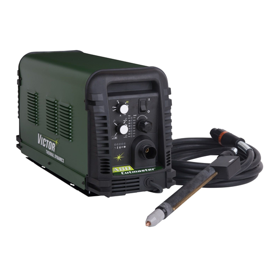
CUTMASTER A80, A120 2.06 Power Supply Features Art # A-08460 Control Panel Torch Leads Receptacle Mounting Rails Work Cable and Clamp Automation Interface Cable Port Input Power Selection Filter Assembly Gas Inlet Port Input Power Cord Art # A-08461 INTRODUCTION... -
Page 19: Section 2 Torch: Introduction
CUTMASTER A80, A120 SECTION 2 TORCH: 18.875" / 479 mm 12.285" / 312 mm INTRODUCTION 2.875” / 73 mm 2T.01 Scope of Manual 1.375" / 35 mm 1.175" / 30 mm 1.75" / 4.95" / 126 mm 0.625" / 44.5 mm... -
Page 20: 04 Options And Accessories
CUTMASTER A80, A120 E. Type Cooling Combination of ambient air and gas stream WARNING through torch. This torch is not to be used with oxygen (O F. Torch Ratings NOTE Automated / Machine Torch Ratings Operating pressure varies with torch model, op- Ambient 104°... - Page 21 CUTMASTER A80, A120 D. Main Cutting Arc DC power is also used for the main cutting arc. The negative output is connected to the torch elec- trode through the torch lead. The positive output is connected to the workpiece via the work cable and to the torch through a pilot wire.
- Page 22 CUTMASTER A80, A120 Remote Pendant PIP Switch Shield Cup To ATC CNC Start PIP Switch To ATC Shield Cup Automation Torch PIP Switch To ATC Shield Cup Parts - In - Place Circuit Diagram for Machine Torch Torch Switch Torch Trigger...
-
Page 23: Section 3 System: Installation
CUTMASTER A80, A120 SECTION 3 SYSTEM: 3.03 Power Supply location and Mounting INSTALLATION NOTE 3.01 Unpacking It is recommended that the unit be secured to a suitable surface using the mounting rails. 1. Use the packing lists to identify and account 1. - Page 24 CUTMASTER A80, A120 NOTE The following illustration and directions are for wiring three phase input power. The upper screws and lower screws are not the same. Do not mix them. The upper screws are Input Power Cable Connections for threading into the plastic of the front and rear Three-Phase (3ø)
-
Page 25: Gas Connections
CUTMASTER A80, A120 7. With a little slack in the wires, tighten the NOTE through - hole protector to secure the power For a secure seal, apply thread sealant to the cable. fitting threads, according to the manufacturer's instructions. Do Not use Teflon tape as a thread 8. - Page 26 CUTMASTER A80, A120 Using High Pressure Air Cylinders 2. Examine the cylinder valves to be sure they are clean and free of oil, grease or any foreign When using high pressure air cylinders as the air material. Briefly open each cylinder valve to supply: blow out any dust which may be present.
-
Page 27: Section 3 Torch: Installation
CUTMASTER A80, A120 Check Air Quality SECTION 3 TORCH: To test the quality of air: INSTALLATION 1. Put the ON / OFF switch in the ON 3T.01 Torch Connections (up) position. If necessary, connect the torch to the Power Supply. - Page 28 CUTMASTER A80, A120 3T.03 Setting Up Automation or Machine Torch NOTE An adapter is required to be installed in the power supply if converting a hand torch system to oper- ate a machine or automation torch. WARNING Disconnect primary power at the source before disassembling the torch or torch leads.
-
Page 29: Section 4 System: Operation
CUTMASTER A80, A120 SECTION 4 SYSTEM: OPERATION 4.01 Front Panel Controls / Features See Illustration for numbering Identification 1. Output Current Control Sets the desired output current. Output settings up to 60 Amps may be used for drag cutting, when hand torch is used and the torch tip contacting the workpiece or higher for standoff cutting. -
Page 30: Preparations For Operation
CUTMASTER A80, A120 4.02 Preparations for Operation Gas indicator turns ON if there is sufficient At the start of each operating session: gas pressure for power supply operation and the cooling fans turn ON. NOTE WARNING Minimum pressure for power supply operation is lower than minimum for torch operation. -
Page 31: Cutting Operation
CUTMASTER A80, A120 Postflow 3. For Drag cutting (60 Amps and below), adjust gas pressure from 75 - 95 psi / 5.2 - 6.5 bar Release the trigger to stop the cutting arc. Gas (LED's in center of control panel). Refer to the continues to flow for approximately 20 seconds. - Page 32 CUTMASTER A80, A120 This Page Intentionally Blank OPERATION Manual 0-5119...
-
Page 33: Section 4 Torch: Operation
CUTMASTER A80, A120 For optimum smooth surface quality, the travel SECTION 4 TORCH: speed should be adjusted so that only the leading OPERATION edge of the arc column produces the cut. If the travel speed is too slow, a rough cut will be pro- duced as the arc moves from side to side in search 4T.01 Machine and Automated Torch... -
Page 34: 02 Automation Torch Parts Selection
CUTMASTER A80, A120 3. Install the replacement Electrode by pushing 4T.02 Automation Torch Parts Selection it straight into the torch head until it clicks. Check the torch for proper consumable parts. The 4 . Install the starter cartridge and desired tip for parts supplied in the torch may not be correct for the operation into the torch head. -
Page 35: 04 Cut Quality
CUTMASTER A80, A120 Cut Surface Torch Head The desired or specified condition (smooth or rough) of the face of the cut. Electrode Nitride Build - Up Nitride deposits can be left on the surface of the cut when nitrogen is present in the plasma gas stream. -
Page 36: 05 General Cutting Information
CUTMASTER A80, A120 Kerf Width Direction of Cut The width of the cut (or the width of material In the torches, the plasma gas stream swirls as it removed during the cut). leaves the torch to maintain a smooth column of gas. - Page 37 CUTMASTER A80, A120 NOTE Trigger The tip should never come in contact with the workpiece except during drag cutting operations. 2. Depending on the cutting operation, do one of the following: Trigger Release a. For edge starts, hold the torch perpendicu-...
- Page 38 CUTMASTER A80, A120 7. Bring the torch within transfer distance to the work. The main arc will transfer to the work, WARNING and the pilot arc will shut OFF. The straight edge must be non - conductive. NOTE The gas preflow and postflow are a character- istic of the power supply and not a function of the torch.
-
Page 39: 07 Gouging
CUTMASTER A80, A120 3. In a portion of the unwanted metal start the 4T.07 Gouging pierce off the cutting line and then continue the cut onto the line. Hold the torch perpendicular to the workpiece after the pierce is complete. - Page 40 CUTMASTER A80, A120 Lead Angle The angle between the torch and workpiece de- pends on the output current setting and torch travel speed. The recommended lead angle is 35°. At a lead angle greater than 45° the molten metal will not be blown out of the gouge and may be blown back onto the torch.
-
Page 41: 08 Recommended Cutting Speeds For Machine And Automated Torches With Exposed Tip
CUTMASTER A80, A120 4T.08 Recommended Cutting Speeds for Machine and Automated Torches With Exposed Tip Mild Steel Air Plasma / Air Shield Standard Shield Cup Deflector Starter Cartridge Electrode Maximum Life Shield Cup 9-8218 9-8243 9-8208 9-8213 9-8232 9-8237 Torch... - Page 42 CUTMASTER A80, A120 Stainless Steel Air Plasma / Air Shield Standard Shield Cup Deflector Starter Cartridge Electrode Maximum Life Shield Cup 9-8218 9-8243 9-8208 9-8213 9-8232 9-8237 Torch Initial Kerf Width Gas Pressure Material Travel Pierce Arc Voltage Working Piercing @ Rec.
- Page 43 CUTMASTER A80, A120 Aluminum Air Plasma / Air Shield Standard Shield Cup Deflector Starter Cartridge Electrode Maximum Life Shield Cup 9-8218 9-8243 9-8208 9-8213 9-8232 9-8237 Torch Initial Kerf Width Gas Pressure Material Travel Pierce Arc Voltage Working Piercing @ Rec.
- Page 44 CUTMASTER A80, A120 Mild Steel Air Plasma / Air Shield Standard Shield Cup Deflector Starter Cartridge Electrode Maximum Life Shield Cup 9-8218 9-8243 9-8210 9-8213 9-8232 9-8237 Initial Kerf Width Gas Pressure Material Torch Working Travel Pierce Arc Voltage Piercing @ Rec.
- Page 45 CUTMASTER A80, A120 Stainless Steel Air Plasma / Air Shield Standard Shield Cup Deflector Starter Cartridge Electrode Maximum Life Shield Cup 9-8218 9-8243 9-8210 9-8213 9-8232 9-8237 Torch Initial Kerf Width Gas Pressure Material Travel Arc Voltage Working Piercing Pierce Delay @ Rec.
- Page 46 CUTMASTER A80, A120 Aluminum Air Plasma / Air Shield Standard Shield Cup Deflector Starter Cartridge Electrode Maximum Life Shield Cup 9-8218 9-8243 9-8210 9-8213 9-8232 9-8237 Torch Initial Kerf Width Gas Pressure Material Travel Pierce Working Piercing @ Rec. (Air)
- Page 47 CUTMASTER A80, A120 Mild Steel Air Plasma / Air Shield Standard Shield Cup Deflector Starter Cartridge Electrode Maximum Life Shield Cup 9-8218 9-8243 9-8211 9-8213 9-8232 9-8237 Torch Initial Kerf Width Gas Pressure Material Travel Pierce Working Piercing @ Rec.
- Page 48 CUTMASTER A80, A120 Stainless Steel Air Plasma / Air Shield Standard Shield Cup Deflector Starter Cartridge Electrode Maximum Life Shield Cup 9-8218 9-8243 9-8211 9-8213 9-8232 9-8237 Torch Initial Kerf Width Gas Pressure Material Travel Pierce Arc Voltage Working Piercing @ Rec.
- Page 49 CUTMASTER A80, A120 Aluminum Air Plasma / Air Shield Standard Shield Cup Deflector Starter Cartridge Electrode Maximum Life Shield Cup 9-8218 9-8243 9-8211 9-8213 9-8232 9-8237 Torch Initial Kerf Width Gas Pressure Material Travel Pierce Working Piercing @ Rec. (Air)
- Page 50 CUTMASTER A80, A120 Mild Steel 100A Air Plasma / Air Shield Standard Shield Cup Deflector Starter Cartridge Electrode Maximum Life Shield Cup 9-8218 9-8213 9-8243 9-8212 9-8232 9-8237 Torch Initial Kerf Width Gas Pressure Material Travel Pierce Working Piercing @ Rec.
- Page 51 CUTMASTER A80, A120 Stainless Steel 100A Air Plasma / Air Shield Standard Shield Cup Deflector Starter Cartridge Electrode Maximum Life Shield Cup 9-8218 9-8213 9-8243 9-8212 9-8232 9-8237 Torch Initial Kerf Width Gas Pressure Material Travel Pierce Working Piercing @ Rec.
- Page 52 CUTMASTER A80, A120 Aluminum 100A Air Plasma / Air Shield Standard Shield Cup Deflector Starter Cartridge Electrode Maximum Life Shield Cup 9-8218 9-8243 9-8212 9-8213 9-8232 9-8237 Torch Initial Kerf Width Gas Pressure Material Travel Pierce Working Piercing @ Rec.
- Page 53 CUTMASTER A80, A120 Mild Steel 120A Air Plasma / Air Shield Standard Shield Cup Deflector Starter Cartridge Electrode Maximum Life Shield Cup 9-8218 9-8213 9-8243 9-8233 9-8232 9-8237 Torch Initial Material Travel Pierce Kerf Width Pressure Working Piercing Thickness Voltage...
- Page 54 CUTMASTER A80, A120 Stainless Steel 120A Air Plasma / Air Shield Standard Shield Cup Deflector Starter Cartridge Electrode Maximum Life Shield Cup 9-8218 9-8213 9-8243 9-8233 9-8232 9-8237 Torch Initial Kerf Width Gas Pressure Material Travel Pierce Working Piercing @ Rec.
- Page 55 CUTMASTER A80, A120 Aluminum 120A Air Plasma / Air Shield Standard Shield Cup Deflector Starter Cartridge Electrode Maximum Life Shield Cup 9-8218 9-8213 9-8243 9-8233 9-8232 9-8237 Torch Initial Kerf Width Gas Pressure Material Travel Pierce Working Piercing @ Rec.
-
Page 56: 09 Recommended Cutting Speeds For Machine And Automated Torches With Shielded Tip
CUTMASTER A80, A120 4T.09 Recommended Cutting Speeds for Machine and Automated Torches With Shielded Tip CUTMASTER A120 Mild Steel ONLY Air Plasma / Air Shield Shield Cap Maximum Life Shield Cup Starter Cartridge Electrode 9-8245 9-8237 9-8208 9-8213 9-8232 Torch... - Page 57 CUTMASTER A80, A120 Stainless Steel CUTMASTER A120 Air Plasma / Air Shield ONLY Shield Cap Maximum Life Shield Cup Starter Cartridge Electrode 9-8245 9-8237 9-8208 9-8213 9-8232 Torch Initial Kerf Width Gas Pressure Material Travel Arc Voltage Working Piercing Pierce Delay @ Rec.
- Page 58 CUTMASTER A80, A120 Aluminum CUTMASTER A120 Air Plasma / Air Shield ONLY Shield Cap Maximum Life Shield Cup Starter Cartridge Electrode 9-8245 9-8237 9-8208 9-8213 9-8232 Torch Initial Kerf Width Gas Pressure Material Travel Pierce Working Piercing @ Rec. (Air)
- Page 59 CUTMASTER A80, A120 Mild Steel Air Plasma / Air Shield Shield Cap Maximum Life Shield Cup Starter Cartridge Electrode 9-8238 9-8237 9-8210 9-8213 9-8232 Torch Initial Kerf Width Gas Pressure Material Travel Pierce Working Piercing @ Rec. (Air) Thickness Voltage...
- Page 60 CUTMASTER A80, A120 Stainless Steel Air Plasma / Air Shield Shield Cap Maximum Life Shield Cup Starter Cartridge Electrode 9-8238 9-8237 9-8210 9-8213 9-8232 Torch Initial Kerf Width Gas Pressure Material Travel Pierce Working Piercing @ Rec. (Air) Thickness Voltage...
- Page 61 CUTMASTER A80, A120 Aluminum Air Plasma / Air Shield Shield Cap Maximum Life Shield Cup Starter Cartridge Electrode 9-8238 9-8237 9-8210 9-8213 9-8232 Torch Initial Kerf Width Gas Pressure Material Travel Pierce Working Piercing @ Rec. (Air) Thickness Voltage Speed...
- Page 62 CUTMASTER A80, A120 Mild Steel Air Plasma / Air Shield Shield Cap Maximum Life Shield Cup Starter Cartridge Electrode 9-8239 9-8237 9-8211 9-8213 9-8232 Torch Initial Kerf Width Gas Pressure Material Travel Working Piercing Pierce Delay @ Rec. (Air) Thickness...
- Page 63 CUTMASTER A80, A120 Stainless Steel Air Plasma / Air Shield Shield Cap Maximum Life Shield Cup Starter Cartridge Electrode 9-8239 9-8237 9-8211 9-8213 9-8232 Torch Initial Kerf Width Gas Pressure Material Travel Pierce Working Piercing @ Rec. (Air) Thickness Voltage...
- Page 64 CUTMASTER A80, A120 Aluminum Air Plasma / Air Shield Shield Cap Maximum Life Shield Cup Starter Cartridge Electrode 9-8239 9-8237 9-8211 9-8213 9-8232 Torch Initial Kerf Width Gas Pressure Material Travel Pierce Arc Voltage Working Piercing @ Rec. (Air) Thickness...
- Page 65 CUTMASTER A80, A120 Mild Steel 100A Air Plasma / Air Shield Shield Cap Maximum Life Shield Cup Starter Cartridge Electrode 9-8239 9-8237 9-8233 9-8213 9-8232 Torch Initial Kerf Width Gas Pressure Material Travel Pierce Arc Voltage Working Piercing @ Rec.
- Page 66 CUTMASTER A80, A120 Stainless Steel 100A Air Plasma / Air Shield Shield Cap Maximum Life Shield Cup Starter Cartridge Electrode 9-8213 9-8239 9-8237 9-8212 9-8232 Torch Initial Kerf Width Gas Pressure Material Travel Pierce Working Piercing @ Rec. (Air) Thickness...
- Page 67 CUTMASTER A80, A120 Aluminum 100A Air Plasma / Air Shield Shield Cap Maximum Life Shield Cup Starter Cartridge Electrode 9-8239 9-8237 9-8212 9-8213 9-8232 Torch Initial Kerf Width Gas Pressure Material Travel Pierce Working Piercing @ Rec. (Air) Thickness Voltage...
- Page 68 CUTMASTER A80, A120 Mild Steel CUTMASTER A120 120A Air Plasma / Air Shield ONLY Shield Cap Maximum Life Shield Cup Starter Cartridge Electrode 9-8213 9-8256 9-8237 9-8233 9-8232 Torch Initial Kerf Width Gas Pressure Material Travel Pierce Working Piercing @ Rec.
- Page 69 CUTMASTER A80, A120 Stainless Steel CUTMASTER A120 120A Air Plasma / Air Shield ONLY Shield Cap Maximum Life Shield Cup Starter Cartridge Electrode 9-8256 9-8237 9-8233 9-8213 9-8232 Torch Initial Kerf Width Gas Pressure Material Travel Pierce Working Piercing @ Rec.
- Page 70 CUTMASTER A80, A120 CUTMASTER A120 Aluminum 120A ONLY Air Plasma / Air Shield Shield Cap Maximum Life Shield Cup Starter Cartridge Electrode 9-8256 9-8237 9-8233 9-8213 9-8232 Torch Initial Kerf Width Gas Pressure Material Travel Pierce Working Piercing @ Rec.
-
Page 71: Patent Information
CUTMASTER A80, A120 PATENT INFORMATION Plasma Cutting Torch Patents The following parts are covered under U.S. and Foreign Patents as follows: Catalog # Description Patent(s) 9-8215 Electrode US Pat No(s) 6163008; 6987238 Other Pat(s) Pending 9-8232 Electrode US Pat No(s) 6163008; 6987238... - Page 72 CUTMASTER A80, A120 Plasma Cutting Torch Patents The following parts are covered under U.S. and Foreign Patents as follows: Catalog # Description Patent(s) 9-8245 Shield Cap US Pat No(s) 6914211; D496951 Other Pat(s) Pending The following parts are also licensed under U.S. Patent No. 5,120,930 and 5,132,512:...
-
Page 73: Section 5 System: Service
CUTMASTER A80, A120 SECTION 5 SYSTEM: SERVICE 5.01 General Maintenance Maintain more often Warning! if used under severe Disconnect input power before maintaining. conditions Each Use Visual check of torch tip and electrode Weekly Visually inspect the cables and leads. -
Page 74: Maintenance Schedule
CUTMASTER A80, A120 5.02 Maintenance Schedule 5.03 Common Faults NOTE Problem - Symptom Common Cause Insufficient 1. Cutting speed too fast. The actual frequency of maintenance may need Penetration 2. Torch tilted too much. to be adjusted according to the operating envi- 3. -
Page 75: Fault Indicator
CUTMASTER A80, A120 5.04 Fault Indicator At initial power up, two lights will temporarily illuminate for 2-3 seconds to show the version of software used. To determine the first digit, count the function indicators left to right, 1 through 5. To determine the second digit count the pressure indicators, reading from bottom to top, 0 through 7. -
Page 76: Basic Troubleshooting Guide
CUTMASTER A80, A120 5.05 Basic Troubleshooting Guide WARNING There are extremely dangerous voltage and power levels present inside this unit. Do not attempt to diagnose or repair unless you have had training in power electronics measurement and troubleshooting techniques. Problem-Symptom... - Page 77 CUTMASTER A80, A120 Problem - Symptom Possible Cause Recommended Action FAULT & 80 PSI 1. Torch shield cup is loose. 1. Tighten shield cup by hand. Do not overtighten. indicators flashing. 2. Torch tip, electrode or starter 2. Turn OFF power supply. Remove shield cup. Install Gas flow is cycling cartridge missing.
-
Page 78: Power Supply Basic Parts Replacement
CUTMASTER A80, A120 C. Filter Element Assembly Replacement 5.06 Power Supply Basic Parts Replacement The Filter Element Assembly is in the rear panel. For better system performance, the filter element should be checked per the Maintenance Schedule (Subsection 5.02), and either cleaned or replaced. - Page 79 CUTMASTER A80, A120 7. Remove the filter element assembly through the rear opening. Housing NOTE If replacing or cleaning just the filter element refer to the following illustration for disassembly. Filter Element (Cat. No. 9-7741) Spring O-ring Filter Element (Cat. No. 9-7743)
- Page 80 CUTMASTER A80, A120 5. Slide out the old Filter Elements. First & Second Stage Cartridges (as marked) Art # A-02942 Optional Two-Stage Filter Replacement 6. Slide the replacement Filter Elements into the Filter Assembly, with the same orientation as noted in Step 4 above.
-
Page 81: Section 5 Torch: Service
CUTMASTER A80, A120 SECTION 5 TORCH: SERVICE 5T.01 General Maintenance NOTE Refer to Previous "Section 5 System" for common and fault indicator descriptions. Upper Groove with Vent Holes Cleaning Torch Must Remain Open Even if precautions are taken to use only clean... -
Page 82: 02 Inspection And Replacement Of Consumable Torch Parts
CUTMASTER A80, A120 5T.02 Inspection and Replacement of 4. Remove the tip. Check for excessive wear (in- dicated by an elongated or oversized orifice). Consumable Torch Parts Clean or replace the tip if necessary. Good Tip Worn Tip WARNING Disconnect primary power to the system before disassembling the torch or torch leads. -
Page 83: Parts Lists
The following items are included with the replacement power supply: work cable & clamp, input power cable, gas pressure regulator / filter, and operating manual. Description Catalog # CutMaster A80 400VAC, Non CE Power Supply With 400V, 3 Phase input power cable 3-1334-3 CutMaster A120 400VAC, Non CE Power Supply... -
Page 84: Replacement Power Supply Parts
CUTMASTER A80, A120 6.04 Replacement Power Supply Parts Description Catalog # Regulator 9-0115 Filter Assembly Replacement Element 9-0116 Input Power Cord for 400 V Power Supply 9-0216 6.05 Options and Accessories Description Catalog # Single - Stage Filter Kit (includes Filter & Hose) - Page 85 CUTMASTER A80, A120 This Page Intentionally Blank Manual 0-5119 PARTS LIST...
-
Page 86: Torch Replacement Parts Sl100Sv Torch (With Solenoid On Mounting Tube)
CUTMASTER A80, A120 6.06 Torch Replacement Parts SL100SV Torch (with Solenoid on Mounting Tube) Item No. Description Catalog # Torch Head Assembly without leads (includes items 2, 3, and 14) 9-8220 Large O-Ring 8-3487 Small O-Ring 8-3486 PIP Switch Kit... - Page 87 CUTMASTER A80, A120 Art # A-07113 Manual 0-5119 PARTS LIST...
-
Page 88: Torch Consumable Parts (Sl100)
CUTMASTER A80, A120 6.07 Torch Consumable Parts (SL100) Ohmic Clip Automation Torch Ohmic Clip 9-8224 Manual Torch 9-8259 20-40A Shield Tip: Shield Cap, Machine Cup Body, STANDOFF 40A 9-8245 9-8237 CUTTING 9-8205 Shield Cap, Deflector Shield Cup 9-8206 9-8243 9-8218... -
Page 89: Replacement Parts For Hand Torch
CUTMASTER A80, A120 6.08 Replacement Parts for Hand Torch Item # Description Catalog # Torch Handle Replacement Kit (includes items No. 2 & 3) 9-7030 Trigger Assembly Replacement Kit 9-7034 Handle Screw Kit (5 each, 6-32 x 1/2” cap screw, and wrench) 9-8062 Torch Head Assembly Replacement Kit (includes items No. - Page 90 CUTMASTER A80, A120 This Page Intentionally Blank PARTS LIST Manual 0-5119...
-
Page 91: Appendix 1: Sequence Of Operation (Block Diagram
CUTMASTER A80, A120 APPENDIX 1: SEQUENCE OF OPERATION (BLOCK DIAGRAM) ACTION: ACTION: ACTION: ACTION: RUN / Rapid Auto Restart / ON / OFF switch to ON Close external RUN / SET / LATCH disconnect switch. Rapid Auto Restart / switch to RUN... -
Page 92: Appendix 2: Data Tag Information
CUTMASTER A80, A120 APPENDIX 2: DATA TAG INFORMATION West Lebanon, NH USA 03784 Manufacturer's Name and/or Logo, Location, Model and M odel : Revision Level, Serial Number and Production Code Dat e of M f r : Made in USA... -
Page 93: Appendix 3: Torch Pin - Out Diagrams
CUTMASTER A80, A120 APPENDIX 3: TORCH PIN - OUT DIAGRAMS A. Automation SL100SV Torch Pin - Out Diagram ATC Female Receptacle - ATC Male Connector - Front View Front View Negative / Plasma Negative / Plasma 4 - Not Used... -
Page 94: Appendix 4: Torch Connection Diagrams
CUTMASTER A80, A120 APPENDIX 4: TORCH CONNECTION DIAGRAMS A. Automation (SL100SV) Torch Connection Diagram Automated CutMaster Power Supply with ATC Torch Receptacle, Automated SL100SV Torch (w/ Solenoid on Positioning Tube), Torch Lead with ATC Connector ATC Male ATC Female Torch Receptacle... - Page 95 CUTMASTER A80, A120 C. Hand Torch Connection Diagram Torch: SL60 / SL100 Hand Torch Leads: Torch Leads with ATC Connector Power Supply: with ATC Receptacle Male ATC Leads ATC Female Power Connector Receptacle Torch Supply Torch Head Leads Black To Power Supply...
-
Page 96: Appendix 5: System Schematic, 208/460V Units
CUTMASTER A80, A120 APPENDIX 5: SYSTEM SCHEMATIC, 208/460V UNITS PRI 3 PRI 3 PRI 4 PRI 4 BIAS SUPPLY PRI 2 PRI 2 PRI 2 PRI 2 INRUSH +12VDC RESISTORS PRI 1 PRI 1 PRI 1 PRI 1 MTH1 MTH1... - Page 97 CUTMASTER A80, A120 A120 ONLY 1TORCH PIP SWITCH PIP SWITCH TORCH SWITCH TORCH SWITCH SEC1 SEC1 SEC2 SEC2 CHOKE1 CHOKE1 +12VDC ATC CONNECTOR AUTOMATION TEMP /OVERTEMP TORCH SOLENOID CIRCUIT -V OUT 1 -V OUT 1 ELECTRODE1 ELECTRODE1 TIP1 TIP1 PILOT IGBT...
-
Page 98: Appendix 6: System Schematic, 380V/400V-600V Units
CUTMASTER A80, A120 APPENDIX 6: SYSTEM SCHEMATIC, 380V/400V-600V UNITS PRI 3 PRI 3 PRI 4 PRI 4 BIAS SUPPLY PRI 2 PRI 2 PRI 2 PRI 2 INRUSH +12VDC RESISTORS PRI 1 PRI 1 PRI 1 PRI 1 MTH1 MTH1... - Page 99 CUTMASTER A80, A120 1TORCH PIP SWITCH PIP SWITCH TORCH SWITCH TORCH SWITCH SEC1 SEC1 SEC2 SEC2 CHOKE1 CHOKE1 +12VDC ATC CONNECTOR AUTOMATION TEMP /OVERTEMP TORCH SOLENOID CIRCUIT -V OUT 1 -V OUT 1 ELECTRODE1 ELECTRODE1 TIP1 TIP1 PILOT IGBT PILOT IGBT...
-
Page 100: Appendix 7: Raw Arc Voltage
CUTMASTER A80, A120 APPENDIX 7: RAW ARC VOLTAGE If raw arc voltage is necessary for the torch height control, the customer must supply an 18 AWG (1.0 mm single pair, unshielded cable rated for 300V or greater. All work must be performed following applicable local and national codes. - Page 101 CUTMASTER A80, A120 Art # A-10288 Work1 (+) Polarity -V out (-) Polarity 5. Tighten the strain relief. 6. Replace the cover. 7. Connect the cable to negative and positive of Torch Height Control . Manual 0-5119 A-11 APPENDIX...
-
Page 102: Appendix 8: Publication History
Updated power cord part number in section 6 per ECOB1234. June 23, 2011 Added Appendix 7: Raw Arc Voltage Mar. 20, 2012 Updated ART A-08066 and changed COO text, per ECOB2149. April 10, 2014 Revised to Victor trade dress standards. APPENDIX A-12 Manual 0-5119... - Page 103 This Page Intentionally Blank...
- Page 104 I N N O V A T I O N T O S H A P E T H E W O R L D ™ U.S. Customer Care: 800-426-1888 / FAX 800-535-0557 Canada Customer Care: 905-827-4515 / FAX 800-588-1714 International Customer Care: 940-381-1212 / FAX 940-483-8178 Printed in ??? © 2012 Victor Technologies International, Inc. www.victortechnologies.com...
Need help?
Do you have a question about the CUTMASTER A80 and is the answer not in the manual?
Questions and answers