
Subscribe to Our Youtube Channel
Related Manuals for Victor CUTMASTER A40


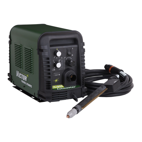
Summary of Contents for Victor CUTMASTER A40
- Page 1 208- 380- 460V 600V 230V 400V CUTMASTER ® AUTOMATED PLASMA CUTTING SYSTEM Operating Manual Art # A-08838_AD Revision: AQ Issue Date: October 24, 2014 Manual No.: 0-4978 VictorThermalDynamics.com...
- Page 2 WE APPRECIATE YOUR BUSINESS! Congratulations on your new Victor Thermal Dynamics product. We are proud to have you as our customer and will strive to provide you with the best service and reliability in the industry. This product is backed by our extensive warranty and world-wide service network. To locate your nearest distributor or service agency call 1-800-426-1888, or visit us on the web at www.VictorThermalDynamics.com.
- Page 3 Plasma Cutting Power Supply CutMaster ® A40 SL100 ™ SV Automated Torch Operating Manual Number 0-4978 Published by: Victor Technologies International, Inc. 82 Benning Street West Lebanon, New Hampshire, USA 03784 www.victorthermaldynamics.com Copyright 2008, 2009, 2010, 2011, 2012, 2013, 2014 by Victor Technologies International, Inc.
-
Page 4: Table Of Contents
TABLE OF CONTENTS SECTION 1: GENERAL INFORMATION ..............1-1 1.01 Notes, Cautions and Warnings ................ 1-1 1.02 Important Safety Precautions ................. 1-1 1.03 Publications ....................1-2 1.04 Note, Attention et Avertissement ..............1-3 1.05 Precautions De Securite Importantes ............. 1-3 1.06 Documents De Reference ................ - Page 5 TABLE OF CONTENTS SECTION 4 TORCH: OPERATION ................ 4T-1 4T.01 Machine and Automated Torch Operation ............4T-1 4T.02 Automation Torch Parts Selection ..............4T-1 4T.03 Machine and Hand Torch Parts Selection ............4T-2 4T.04 Cut Quality .....................4T-3 4T.05 General Cutting Information ................4T-3 4T.06 Hand Torch Operation ..................4T-4 4T.07 Gouging ......................4T-7...
- Page 6 TABLE OF CONTENTS APPENDIX 1: SEQUENCE OF OPERATION (BLOCK DIAGRAM) .................. A-1 APPENDIX 2: DATA TAG INFORMATION ..............A-2 APPENDIX 3: TORCH PIN - OUT DIAGRAMS ............A-3 APPENDIX 4: TORCH CONNECTION DIAGRAMS ............A-4 APPENDIX 5: SYSTEM SCHEMATIC, 208/460V UNITS ..........A-6 APPENDIX 6: SYSTEM SCHEMATIC, 400V/600V UNITS ..........
-
Page 7: Section 1: General Information
CUTMASTER A40 SECTION 1: GENERAL INFORMATION GASES AND FUMES Gases and fumes produced during the plasma cutting process can be dangerous and hazardous to your health. 1.01 NOTES, CAUTIONS AND WARNINGS • Keep all fumes and gases from the breathing area. Keep Throughout this manual, notes, cautions, and warnings are your head out of the welding fume plume. -
Page 8: Publications
CUTMASTER A40 • Keep helmet and safety glasses in good condition. Re- • Disconnect power source before performing any service or repairs. place lenses when cracked, chipped or dirty. • Protect others in the work area from the arc rays. Use • Read and follow all the instructions in the Operating protective booths, screens or shields. Manual. • Use the shade of lens as suggested in the following per ANSI/ASC Z49.1: FIRE AND EXPLOSION... -
Page 9: Note, Attention Et Avertissement
CUTMASTER A40 7. AWS Standard A6.0, WELDING AND CUTTING CON- TAINERS WHICH HAVE HELD COMBUSTIBLES, obtain- able from American Welding Society, 550 N.W. LeJeune AVERTISSEMENT Rd, Miami, FL 33126 Toute procédure pouvant provoquer des blessures 8. NFPA Standard 51, OXYGEN-FUEL GAS SYSTEMS de l’opérateur ou des autres personnes se trouvant... - Page 10 CUTMASTER A40 • Les sortes de gaz et de fumée provenant de l’arc de plasma dépendent du genre de métal utilisé, des revêtements se INCENDIE ET EXPLOSION trouvant sur le métal et des différents procédés. Vous devez prendre soin lorsque vous coupez ou soudez tout métal Les incendies et les explosions peuvent résulter des scories pouvant contenir un ou plusieurs des éléments suivants:...
-
Page 11: Documents De Reference
CUTMASTER A40 • Maintenez votre casque et vos lunettes de protection en bon 1.06 DOCUMENTS DE REFERENCE état. Remplacez toute lentille sale ou comportant fissure Consultez les normes suivantes ou les révisions les plus récentes ou rognure. ayant été faites à celles-ci pour de plus amples renseignements : • Protégez les autres personnes se trouvant sur la zone de 1. - Page 12 CUTMASTER A40 2. Norme ANSI Z49.1, LA SÉCURITÉ DES OPÉRATIONS DE COUPE ET DE SOUDAGE, disponible auprès de la Société Américaine de Soudage (American Welding Society), 550 N.W. LeJeune Rd., Miami, FL 33126 3. NIOSH, LA SÉCURITÉ ET LA SANTÉ LORS DES OPÉRATIONS DE COUPE ET DE SOUDAGE À L’ARC ET AU GAZ, disponible auprès du Superintendent of Documents, U.S.
-
Page 13: Declaration Of Conformity
Rigorous testing is incorporated into the manufacturing process to ensure the manufactured product meets or exceeds all design specifications. Victor Technologies. has been manufacturing products for more than 30 years, and will continue to achieve excellence in our area of manufacture. - Page 14 CUTMASTER A40 Classification: The equipment described in this manual is Class A and intended for industrial use. WARNING This Class A equipment is not intended for use in residential locations where the electrical power is provided by the public low-voltage supply system. There may be potential difficulties in ensuring electromagnetic compatibility in those locations, due to conducted as well as radiated disturbances.
-
Page 15: Statement Of Warranty
Victor Thermal Dynamics Corporation will honor warranty claims submitted within the warranty periods listed below. All warranty periods begin on the date of sale of the product to the original retail customer or 1 year after sale to an authorized Victor Thermal Dynamics Distributor. - Page 16 CUTMASTER A40 This Page Intentnionally Blank GENERAL INFORMATION Manual 0-4978 1-10...
-
Page 17: Section 2 System: Introduction
Owner’s Manual number and equipment identification numbers. Electronic copies of this manual can also be downloaded at no charge in Acrobat PDF format by going to the Victor Thermal Dynamics web site listed below and clicking on Thermal Dynam- ics and then on the Literature link: http://www.victorthermaldynamics.com... -
Page 18: Power Supply Specifications
20 - 60 Amps, Continuously Adjustable Power Supply Gas Particulates to 5 Microns Filtering Ability CutMaster A40 Power Supply Duty Cycle * Duty Cycle Ratings @ 40° C (104° F) Ambient Temperature Operating Range 0° - 50° C IEC Rating... -
Page 19: Input Wiring Specifications
CUTMASTER A40 2.05 INPUT WIRING SPECIFICATIONS CutMaster A40 Power Supply Input Cable Wiring Requirements Input voltage Freq Power Input Suggested Sizes Flexible Cord Volts I max I1eff Fuse (amps) (Min. AWG) 10.4 1 Phase 10.8 15.2 50/60 50/60 3 Phase... -
Page 20: Power Supply Features
CUTMASTER A40 2.06 POWER SUPPLY FEATURES Control Panel Art # A-08306 Torch Leads Receptacle Mounting Rails Work Cable and Clamp Automation Interface Cable Port Input Power Selection Filter Assembly Gas Inlet Port Input Power Cord Art # A-08318 INTRODUCTION Manual 0-4978... -
Page 21: Section 2 Torch: Introduction
CUTMASTER A40 SECTION 2 TORCH: 2. Machine /Mechanized Torch, Model The standard machine torch has a positioning tube with INTRODUCTION rack & pinch block assembly. 15.875" / 403 mm 9.285" / 236 mm 2T.01 SCOPE OF MANUAL This manual contains descriptions, operating instructions and maintenance procedures for the 1Torch Models SL60/Manual, 1.175"... -
Page 22: 04 Options And Accessories
CUTMASTER A40 2T.05 INTRODUCTION TO PLASMA Manual Torch Ratings Ambient 104° F A. Plasma Gas Flow Temperature 40° C Plasma is a gas which has been heated to an extremely Duty Cycle 100% @ 60 Amps @ 400 scfh high temperature and ionized so that it becomes electri-... - Page 23 CUTMASTER A40 B. Gas Distribution Remote Pendant The single gas used is internally split into plasma and secondary gases. The plasma gas flows into the torch through the negative lead, through the starter cartridge, around the electrode, PIP Switch Shield Cup To ATC and out through the tip orifice.
- Page 24 CUTMASTER A40 This Page Intentionally Blank 2T-4 INTRODUCTION Manual 0-4978...
-
Page 25: Section 3 System: Installation
CUTMASTER A40 SECTION 3 SYSTEM: 2. Place the unit in the desired position and mark where INSTALLATION the four keyway holes in the mounting rails touch. 3.01 UNPACKING 3. Remove the unit and using these markings, prepare holes for mounting hardware. - Page 26 CUTMASTER A40 Most units are shipped from the factory with a 230Volt input C. Input Power Selection power cable wired to the input contactor in the single - phase Set the Input Voltage Selection Switch at the rear of the unit configuration.
- Page 27 CUTMASTER A40 E. Connections to Single Phase Input Power Connections to Three Phase Input Power WARNING WARNING Disconnect input power from the power supply Disconnect input power from the power supply and input cable before attempting this procedure. and input cable before attempting this procedure.
-
Page 28: Gas Connections
CUTMASTER A40 3.06 GAS CONNECTIONS Filter Assembly Connecting Gas Supply to Unit Inlet Port The connection is the same for compressed air or high pressure cylinders. Refer to the following subsections if an optional air line filter is to be installed. - Page 29 CUTMASTER A40 Installing Optional Two - Stage Air Filter Kit 1. Refer to the manufacturer’s specifications for instal- lation and maintenance procedures for high pressure This optional two - stage air line filter is also for use on regulators. compressed air shop systems. Filter removes moisture and contaminants to at least 5 microns.
- Page 30 CUTMASTER A40 This Page Intentionally Blank INSTALLATION Manual 0-4978...
-
Page 31: Section 3 Torch: Installation
Cable Port If necessary, connect the torch to the Power Supply. Connect only the Victor Thermal Dynamics model SL100SV / Automa- tion, SL100 / Mechanical or SL60 / Manual Torch to this power supply. Maximum torch leads length is 100 feet / 30.5 m, including extensions. - Page 32 CUTMASTER A40 There are three options for Divided Arc Voltage signal supplied from the automation interface pcb. This is selected by connecting the black Jumper Plug on the P1 connector as follows: Arc voltage / 16.67 Jumper not installed Arc voltage / 30 Jumper Pins 1 & 2 . This is the factory default position of the jumper Arc voltage / 50 Jumper Pins 2 &...
-
Page 33: 03 Setting Up Automation Or Machine Torch
CUTMASTER A40 3T.03 Setting Up Automation or Machine Torch NOTE An adapter is required to be installed in the power supply if converting a hand torch system to operate a machine or automation torch. WARNING Disconnect primary power at the source before disassembling the torch or torch leads. - Page 34 CUTMASTER A40 This page intentionally blank 3T-4 INSTALLATION Manual 0-4978...
-
Page 35: Section 4 System: Operation
CUTMASTER A40 SECTION 4 SYSTEM: OPERATION 4.01 FRONT PANEL CONTROLS / FEATURES See Illustration for numbering Identification 1. Output Current Control Sets the desired output current. Output settings up to 60 Amps may be used for drag cutting (with the torch tip contacting the workpiece) or higher for standoff cutting. -
Page 36: Preparations For Operation
ON if there is sufficient gas pressure for power supply Torch Connection operation and the cooling fans turn ON. Check that the torch is properly connected. Only Victor NOTE Thermal Dynamics model SL60 / Manual, SL100 / Mechani- cal or SL100 / SV Automation Torches may be connected Minimum pressure for power supply operation is to this Power Supply. - Page 37 STANDOFF stantly, and the cutting arc restarts instantly when the pilot arc contacts the workpiece. (Use the 'Rapid Auto Restart' CutMaster A40 Gas Pressure Settings position when cutting expanded metal or gratings, or in SL100 gouging or trimming operations when an uninterrupted...
- Page 38 CUTMASTER A40 This Page Intentionally Blank OPERATION Manual 0-4978...
-
Page 39: Section 4 Torch: Operation
CUTMASTER A40 SECTION 4 TORCH: Travel speed also affects the bevel angle of a cut. When cutting in a circle or around a corner, slowing down the OPERATION travel speed will result in a squarer cut. The power source output should be reduced also. Refer to the appropriate Control Module Operating Manual for any Corner Slow- 4T.01... -
Page 40: Machine And Hand Torch Parts Selection
CUTMASTER A40 4T.03 MACHINE AND HAND TORCH PARTS SELECTION WARNING Depending on the type of operation to be done determines the torch parts to be used. Disconnect primary power at the source before assembling or disassembling torch parts, or torch Type of operation: and leads assemblies. -
Page 41: 04 Cut Quality
CUTMASTER A40 3. Install the replacement Electrode by pushing it straight Bottom Dross Buildup into the torch head until it clicks. Molten material which is not blown out of the cut area and resolidifies on the plate. Excessive dross may require 4 . -
Page 42: 06 Hand Torch Operation
CUTMASTER A40 life. Standoff may also significantly affect the bevel angle. 4T.06 HAND TORCH OPERATION Reducing standoff will generally result in a more square cut. Standoff Cutting With Hand Torch Edge Starting For edge starts, hold the torch perpendicular to the work-... - Page 43 CUTMASTER A40 8. For a consistent standoff height from the workpiece, install the standoff guide by sliding it onto the torch shield cup. Install the guide with the legs at the sides of the shield cup body to maintain good visibility of the cutting arc.
- Page 44 CUTMASTER A40 1. Install the drag cutting tip and set the output current. NOTE 2. The torch can be comfortably held in one hand or When the shield cup is properly installed, there is a slight gap between the shield cup and the steadied with two hands.
-
Page 45: 07 Gouging
CUTMASTER A40 Gouging Parameters NOTE Gouging performance depends on parameters such as The gas preflow and postflow are a characteristic torch travel speed, current level, lead angle (the angle be- of the power supply and not a function of the torch. - Page 46 CUTMASTER A40 Torch Head 35° Standoff Height Workpiece A-00941_AB Gouging Angle and Standoff Distance Standoff Distance The tip to work distance affects gouge quality and depth. Standoff distance of 1/8 - 1/4 inch (3 - 6 mm) allows for smooth, consistent metal removal. Smaller standoff dis- tances may result in a severance cut rather than a gouge.
- Page 47 CUTMASTER A40 This page intentionally blank. Manual 0-4978 OPERATION 4T-9...
-
Page 48: 08 Recommended Cutting Speeds For Machine And Automated Torches With Exposed Tip
CUTMASTER A40 4T.08 RECOMMENDED CUTTING SPEEDS FOR MACHINE AND AUTOMATED TORCHES WITH EXPOSED TIP Mild Steel Air Plasma / Air Shield Starter Cartridge Standard Shield Cup Deflector Heavy Duty Starter Electrode Maximum Life Shield Cup Cartridge 9-8218 9-8213 9-8243 9-8208... - Page 49 CUTMASTER A40 Material Torch Working Initial Piercing Kerf Width Gas Pressure (Air) Arc Voltage Travel Speed Pierce Delay Thickness Height Height @ Rec. Speed (mm) Volts (mm) (mm/min) (mm) (sec) (mm) (torch lead length) 3990 2920 1810 1470 4.8 (7.6m) 1345 5.2 (15.2m)
- Page 50 CUTMASTER A40 Stainless Steel Air Plasma / Air Shield Starter Cartridge Standard Shield Cup Deflector Heavy Duty Starter Electrode Maximum Life Shield Cup Cartridge 9-8218 9-8213 9-8243 9-8208 9-8232 9-8237 9-8277 Kerf Width Material Gas Pressure Torch Working Initial Piercing Arc Voltage...
- Page 51 CUTMASTER A40 Kerf Width Material Torch Working Initial Piercing Gas Pressure (Air) Arc Voltage Travel Speed Pierce Delay @ Rec. Thickness Height Height Speed (mm) Volts (mm) (mm/min) (mm) (sec) (mm) (torch lead length) 1670 1140 5.2 (7.6) 5.5 (15.2) Edge Start BOLD TYPE indicates maximum piercing parameters.
- Page 52 CUTMASTER A40 Aluminum Air Plasma / Air Shield Starter Cartridge Standard Shield Cup Deflector Heavy Duty Starter Electrode Maximum Life Shield Cup Cartridge 9-8218 9-8213 9-8243 9-8208 9-8232 9-8237 9-8277 Material Gas Pressure Torch Working Initial Piercing Kerf Width Arc Voltage...
- Page 53 CUTMASTER A40 Material Torch Working Initial Piercing Kerf Width Gas Pressure (Air) Arc Voltage Travel Speed Pierce Delay Thickness Height Height @ Rec. Speed (mm) Volts (mm) (mm/min) (mm) (sec) (mm) (torch lead length) 7620 3500 2350 4.8 (7.6m) 2170 1740 5.2 (15.2m)
- Page 54 CUTMASTER A40 Mild Steel Air Plasma / Air Shield Starter Cartridge Standard Shield Cup Deflector Heavy Duty Starter Electrode Maximum Life Shield Cup Cartridge 9-8218 9-8213 9-8243 9-8210 9-8232 9-8237 9-8277 Material Gas Pressure Torch Working Initial Piercing Kerf Width Arc Voltage...
- Page 55 CUTMASTER A40 Material Torch Working Initial Piercing Kerf Width Gas Pressure (Air) Arc Voltage Travel Speed Pierce Delay Thickness Height Height @ Rec. Speed (mm) Volts (mm) (mm/min) (mm) (sec) (mm) (torch lead length) 7540 7015 0.10 4570 0.10 3650 0.20 2465 0.20...
- Page 56 CUTMASTER A40 Stainless Steel Air Plasma / Air Shield Starter Cartridge Standard Shield Cup Deflector Heavy Duty Starter Electrode Maximum Life Shield Cup Cartridge 9-8218 9-8213 9-8243 9-8210 9-8232 9-8237 9-8277 Kerf Width Material Gas Pressure Torch Working Initial Piercing Arc Voltage...
- Page 57 CUTMASTER A40 Kerf Width Material Torch Working Initial Piercing Gas Pressure (Air) Arc Voltage Travel Speed Pierce Delay @ Rec. Thickness Height Height Speed (mm) (torch lead Volts (mm) (mm/min) (mm) (sec) (mm) length) 10890 0.00 7560 0.10 4365 0.10 2865 0.20...
- Page 58 CUTMASTER A40 Aluminum Air Plasma / Air Shield Starter Cartridge Standard Shield Cup Deflector Heavy Duty Starter Electrode Maximum Life Shield Cup Cartridge 9-8218 9-8213 9-8243 9-8210 9-8232 9-8237 9-8277 Kerf Width Material Gas Pressure Torch Working Initial Piercing Arc Voltage...
- Page 59 CUTMASTER A40 Torch Initial Kerf Width Material Gas Pressure Arc Voltage Working Travel Speed Piercing Pierce Delay @ Rec. Thickness (Air) Height Height Speed (mm) (torch lead Volts (mm) (mm/min) (mm) (sec) (mm) length) 17010 0.00 7680 0.10 6410 0.10 5230 0.20...
- Page 60 CUTMASTER A40 This page intentionally blank. 4T-22 OPERATION Manual 0-4978...
- Page 61 CUTMASTER A40 This page intentionally blank. Manual 0-4978 OPERATION 4T-23...
-
Page 62: 09 Recommended Cutting Speeds For Machine And Automated Torches With Shielded Tip
CUTMASTER A40 4T.09 RECOMMENDED CUTTING SPEEDS FOR MACHINE AND AUTOMATED TORCHES WITH SHIELDED TIP Mild Steel Air Plasma / Air Shield Starter Cartridge Shield Cap Maximum Life Shield Cup Heavy Duty Starter Cartridge Electrode 9-8213 9-8245 9-8237 9-8208 9-8232 9-8277... - Page 63 CUTMASTER A40 Kerf Width Material Torch Working Initial Piercing Gas Pressure (Air) Arc Voltage Travel Speed Pierce Delay @ Rec. Thickness Height Height Speed (mm) Volts (mm) (mm/min) (mm) (sec) (mm) (torch lead length) 3266 2239 1794 1651 5.2 (7.6) 1578 5.5 (15.2)
- Page 64 CUTMASTER A40 Stainless Steel Air Plasma / Air Shield Starter Cartridge Shield Cap Maximum Life Shield Cup Electrode Heavy Duty Starter Cartridge 9-8213 9-8245 9-8237 9-8208 9-8232 9-8277 Kerf Width Material Gas Pressure Torch Working Initial Piercing Arc Voltage Travel Speed Pierce Delay @ Rec.
- Page 65 CUTMASTER A40 Kerf Width Material Torch Working Initial Piercing Gas Pressure (Air) Arc Voltage Travel Speed Pierce Delay @ Rec. Thickness Height Height Speed (mm) Volts (mm) (mm/min) (mm) (sec) (mm) (torch lead length) 1670 1140 5.2 (7.6) 5.5 (15.2) BOLD TYPE indicates maximum piercing parameters.
- Page 66 CUTMASTER A40 Aluminum Air Plasma / Air Shield Starter Cartridge Shield Cap Maximum Life Shield Cup Heavy Duty Starter Electrode Cartridge 9-8213 9-8245 9-8237 9-8208 9-8232 9-8277 Material Gas Pressure Torch Working Initial Piercing Kerf Width Arc Voltage Travel Speed...
- Page 67 CUTMASTER A40 Material Torch Working Initial Piercing Kerf Width Gas Pressure (Air) Arc Voltage Travel Speed Pierce Delay Thickness Height Height @ Rec. Speed (mm) Volts (mm) (mm/min) (mm) (sec) (mm) (torch lead length) 7660 3490 2350 5.2 (7.6) 2170 5.5 (15.2) 1630 10.0...
- Page 68 CUTMASTER A40 Mild Steel Air Plasma / Air Shiel Starter Cartridge Shield Cap Maximum Life Shield Cup Heavy Duty Starter Electrode Cartridge 9-8213 9-8238 9-8237 9-8210 9-8232 9-8277 Material Gas Pressure Torch Working Initial Piercing Kerf Width Arc Voltage Travel Speed...
- Page 69 CUTMASTER A40 Material Torch Working Initial Piercing Kerf Width Gas Pressure (Air) Arc Voltage Travel Speed Pierce Delay Thickness Height Height @ Rec. Speed (mm) Volts (mm) (mm/min) (mm) (sec) (mm) (torch lead length) 6804 5942 0.10 5080 0.10 3316 0.20 2794 0.20...
- Page 70 CUTMASTER A40 Stainless Steel Air Plasma / Air Shield Starter Cartridge Shield Cap Maximum Life Shield Cup Heavy Duty Starter Electrode Cartridge 9-8213 9-8238 9-8237 9-8210 9-8232 9-8277 Material Gas Pressure Torch Working Initial Piercing Kerf Width Arc Voltage Travel Speed...
- Page 71 CUTMASTER A40 Material Torch Working Initial Piercing Kerf Width Gas Pressure (Air) Arc Voltage Travel Speed Pierce Delay Thickness Height Height @ Rec. Speed (mm) Volts (mm) (mm/min) (mm) (sec) (mm) (torch lead length) 4590 0.00 3925 0.10 3285 0.10 1985 0.20...
- Page 72 CUTMASTER A40 Aluminum Air Plasma / Air Shield Starter Cartridge Shield Cap Maximum Life Shield Cup Heavy Duty Starter Electrode Cartridge 9-8213 9-8238 9-8237 9-8210 9-8232 9-8277 Material Gas Pressure Torch Working Initial Piercing Kerf Width Arc Voltage Travel Speed Pierce Delay...
- Page 73 CUTMASTER A40 Material Torch Working Initial Piercing Kerf Width Gas Pressure (Air) Arc Voltage Travel Speed Pierce Delay Thickness Height Height @ Rec. Speed (mm) Volts (mm) (mm/min) (mm) (sec) (mm) (torch lead length) 8890 0.00 8890 0.10 7070 0.10 5095 0.20...
-
Page 74: Patent Information
CUTMASTER A40 PATENT INFORMATION Plasma Cutting Torch Patents The following parts are covered under U.S. and Foreign Patents as follows: Catalog # Description Patent(s) 9-8215 Electrode US Pat No(s) 6163008; 6987238 Other Pat(s) Pending 9-8232 Electrode US Pat No(s) 6163008; 6987238 Other Pat(s) Pending 9-8213 Cartridge US Pat No(s) 6903301; 6717096; 6936786; 6703581; D496842; D511280; D492709;... - Page 75 CUTMASTER A40 Catalog # Description Patent(s) 9-8239 Shield Cap US Pat No(s) 6914211; D496951 Other Pat(s) Pending 9-8244 Shield Cap US Pat No(s) 6914211; D505309 Other Pat(s) Pending 9-8245 Shield Cap US Pat No(s) 6914211; D496951 Other Pat(s) Pending The following parts are also licensed under U.S. Patent No. 5,120,930 and 5,132,512: Catalog # Description...
- Page 76 CUTMASTER A40 This page intentionally blank. 4T-38 OPERATION Manual 0-4978...
-
Page 77: Section 5 System: Service
CUTMASTER A40 SECTION 5 SYSTEM: SERVICE 5.01 GENERAL MAINTENANCE Maintain more often Warning! if used under severe Disconnect input power before maintaining. conditions Each Use Visual check of torch tip and electrode Weekly Visually inspect the cables and leads. Replace as needed... -
Page 78: Maintenance Schedule
4. Worn torch parts Daily Operational Checks or Every Six Cutting Hours: 5. Cutting current too low. 6. Non - Genuine Victor Thermal 1. Check torch consumable parts, replace if damaged, Dynamics parts used worn or when cut performance has diminished. -
Page 79: Fault Indicator
CUTMASTER A40 5.04 FAULT INDICATOR Explanation of Faults " UNDER PRESSURE: Indicates that operating pressure At initial power up, two lights will temporarily illuminate for 2-3 is set too low and power supply output power will be seconds to show the version of software used. -
Page 80: Basic Troubleshooting Guide
CUTMASTER A40 5.05 BASIC TROUBLESHOOTING GUIDE WARNING There are extremely dangerous voltage and power levels present inside this unit. Do not attempt to diagnose or repair unless you have had training in power electronics measurement and troubleshooting techniques. Problem - Symptom Possible Cause... - Page 81 CUTMASTER A40 Problem - Symptom Possible Cause Recommended Action FAULT & 80 PSI 1. Torch shield cup is loose. 1. Tighten shield cup by hand. Do not overtighten. indicators flashing. 2. Torch tip, electrode or starter 2. Turn OFF power supply. Remove shield cup. Install Gas flow is cycling cartridge missing.
-
Page 82: Circuit Fault Isolation
CUTMASTER A40 B. Cover Installation 5.06 CIRCUIT FAULT ISOLATION 1. Reverse previous procedures for cover installation. NOTE WARNING When installing the upper screws, attempt to reuse the original threads. The easiest way to do this is The following procedures should not be attempted... - Page 83 CUTMASTER A40 7. Remove the filter element assembly through the rear opening. NOTE If replacing or cleaning just the filter element refer to the following illustration for disassembly. Filter Element Art # A-07989 Art # A-07990 8. Install the new or cleaned assembly by reversing these procedures.
- Page 84 CUTMASTER A40 Optional Single-Stage Filter Element Replacement Optional Two-Stage Filter Element Replacement These instructions apply to power supplies where the optional The Two-Stage Air Filter has two Filter Elements. When the Filter Single-Stage Filter has been installed. Elements become dirty the Power Supply will continue to oper- ate but cut quality may become unacceptable.
-
Page 85: Section 5 Torch: Service
CUTMASTER A40 SECTION 5 TORCH: SERVICE Upper Groove 5T.01 GENERAL MAINTENANCE with Vent Holes Must Remain Open NOTE Upper O-Ring Refer to Previous "Section 5 System" for in Correct Groove common and fault indicator descriptions. Threads Cleaning Torch Lower O-Ring... -
Page 86: 02 Inspection And Replacement Of Consumable Torch Parts
CUTMASTER A40 Good Tip Worn Tip 5T.02 INSPECTION AND REPLACEMENT OF CONSUMABLE TORCH PARTS A-03406 WARNING Example of Tip Wear Disconnect primary power to the system before 5. Remove the starter cartridge. Check for excessive wear, disassembling the torch or torch leads. -
Page 87: Section 6: Parts Lists
CUTMASTER A40 SECTION 6: PARTS LISTS 6.01 INTRODUCTION A. Parts List Breakdown The parts list provide a breakdown of all replaceable components. The parts lists are arranged as follows: Section "6.03 Power Supply Replacement" Section "6.04 Replacement Power Supply Parts"... -
Page 88: Replacement Power Supply Parts
CUTMASTER A40 6.04 REPLACEMENT POWER SUPPLY PARTS Description Catalog # Regulator 9-0115 Filter Assembly Replacement Element 9-0116 Input Power Cord for 208 / 230V Power Supply 9-8596 Input Power Cord for 400 V Power Supply 9-0218 Input Power Cord for 460 and 600 V Power Supply 9-8563 6.05... - Page 89 CUTMASTER A40 This Page Intentionally Blank. Manual 0-4978 PARTS LIST...
-
Page 90: Torch Replacement Parts Sl100Sv Torch (With Solenoid On Mounting Tube)
CUTMASTER A40 6.06 TORCH REPLACEMENT PARTS SL100SV TORCH (WITH SOLENOID ON MOUNTING TUBE) Item No. Description Catalog No. Torch Head Assembly without leads (includes items 2, 3, and 14) 9-8220 Large O-Ring 8-3487 Small O-Ring 8-3486 PIP Switch Kit 9-7036 PIP Plunger and Return Spring Kit 9-7045 Automated Leads Assemblies with ATC connectors 25 - foot / 7.6 m Leads Assembly with ATC connector... - Page 91 CUTMASTER A40 Art # A-07113 Manual 0-4978 PARTS LIST...
-
Page 92: Torch Consumable Parts (Sl100 Sv) Automation
CUTMASTER A40 6.07 TORCH CONSUMABLE PARTS (SL100 SV) AUTOMATION Ohmic Clip Automation Torch Ohmic Clip 9-8224 Manual Torch 9-8259 20-40A Shield Tip: Shield Cap, Machine Cup Body, STANDOFF 40A 9-8245 9-8237 CUTTING 9-8205 Shield Cap, Deflector Shield Cup 9-8206 9-8243... -
Page 93: Torch Consumable Parts Manual (Sl60)Torch
CUTMASTER A40 6.08 TORCH CONSUMABLE PARTS MANUAL (SL60)TORCH Tips: Shield DRAG TIP Cup Body, Shield Cap, Deflector 9-8237 CUTTING 9-8243 20A 9-8205 30A 9-8206 Shield Cup 40A 9-8207 9-8218 60A 9-8252 O-Ring No. 8-3488 Shield Cap, Drag DRAG SHIELD 40A 9-8244... -
Page 94: Replacement Parts For Hand Torch
CUTMASTER A40 6.09 REPLACEMENT PARTS FOR HAND TORCH Item # Description Catalog # Torch Handle Replacement Kit (includes items No. 2 & 3) 9-7030 Trigger Assembly Replacement Kit 9-7034 Handle Screw Kit (5 each, 6-32 x 1/2” cap screw, and wrench) 9-8062 Torch Head Assembly Replacement Kit (includes items No. 5 & 6) 9-8219 Large O-Ring 8-3487 Small O-Ring 8-3486 Leads Assemblies with ATC connectors (includes switch assemblies) SL60, 20 - foot Leads Assembly with ATC connector... - Page 95 CUTMASTER A40 This Page Intentionally Blank. Manual 0-4978 PARTS LIST...
- Page 96 CUTMASTER A40 This Page Intentionally Blank. 6-10 PARTS LIST Manual 0-4978...
-
Page 97: Appendix 1: Sequence Of Operation (Block Diagram
CUTMASTER A40 APPENDIX 1: SEQUENCE OF OPERATION (BLOCK DIAGRAM) ACTION: ACTION: ACTION: ACTION: RUN / Rapid Auto Restart / ON / OFF switch to ON Close external RUN / SET / LATCH disconnect switch. Rapid Auto Restart / switch to RUN... - Page 98 CUTMASTER A40 This page intentionally blank. APPENDIX Manual 0-4978...
-
Page 99: Appendix 2: Data Tag Information
CUTMASTER A40 APPENDIX 2: DATA TAG INFORMATION West Lebanon, NH USA 03784 Manufacturer's Name and/or Logo, Location, Model and Revision Level, Serial Number M odel : and Production Code Dat e of M f r : Made in USA Type of Power... - Page 100 CUTMASTER A40 This page intentionally blank. APPENDIX Manual 0-4978...
-
Page 101: Appendix 3: Torch Pin - Out Diagrams
CUTMASTER A40 APPENDIX 3: TORCH PIN - OUT DIAGRAMS A. Automation SL100SV Torch Pin - Out Diagram ATC Female Receptacle - ATC Male Connector - Front View Front View Negative / Plasma Negative / Plasma 4 - Not Used 8 - Open... -
Page 102: Appendix 4: Torch Connection Diagrams
CUTMASTER A40 APPENDIX 4: TORCH CONNECTION DIAGRAMS A. Automation (SL100SV) Torch Connection Diagram Automated CutMaster Power Supply with ATC Torch Receptacle, Automated SL100SV Torch (w/ Solenoid on Positioning Tube), Torch Lead with ATC Connector ATC Female ATC Male Torch Receptacle... - Page 103 CUTMASTER A40 C. Hand Torch Connection Diagram Torch: SL60 / SL100 Hand Torch Leads: Torch Leads with ATC Connector Power Supply: with ATC Receptacle Male ATC Leads ATC Female Receptacle Power Connector Torch Torch Supply Head Leads Black To Power Supply...
-
Page 104: Appendix 5: System Schematic, 208/460V Units
CUTMASTER A40 APPENDIX 5: SYSTEM SCHEMATIC, 208/460V UNITS K1-K4 K1-K4 K5, K6 K5, K6 PRI 2 PRI 2 PRI 1 PRI 1 PRI 4 PRI 4 PRI 3 PRI 3 +12VDC BIAS SUPPLY MTH2 MTH2 MTH1 MTH1 C1-C4* C1-C4* /INRUSH... - Page 105 CUTMASTER A40 CM82 / A60 ONLY 1TORCH PIP SWITCH PIP SWITCH SEC1 SEC1 SEC2 SEC2 CHOKE1 CHOKE1 +12VDC TORCH SWITCH TORCH SWITCH TEMP /OVERTEMP CIRCUIT ATC CONNECTOR AUTOMATION TORCH SOLENOID -V OUT 1 -V OUT 1 ELECTRODE1 ELECTRODE1 TIP1 TIP1...
-
Page 106: Appendix 6: System Schematic, 400V/600V Units
CUTMASTER A40 APPENDIX 6: SYSTEM SCHEMATIC, 400V/600V UNITS PRI 1 PRI 1 PRI 2 PRI 2 PRI 4 PRI 4 PRI 3 PRI 3 BIAS SUPPLY MTH1 MTH1 MTH2 MTH2 +12VDC + C1-C4* + C1-C4* CHOKE /INRUSH CE UNITS ONLY... - Page 107 CUTMASTER A40 1TORCH PIP SWITCH PIP SWITCH SEC1 SEC1 SEC2 SEC2 CHOKE1 CHOKE1 +12VDC TORCH SWITCH TORCH SWITCH TEMP /OVERTEMP CIRCUIT ATC CONNECTOR AUTOMATION TORCH SOLENOID -V OUT 1 -V OUT 1 ELECTRODE1 ELECTRODE1 TIP1 TIP1 PILOT IGBT PILOT IGBT...
-
Page 108: Appendix 7: Raw Arc Voltage
CUTMASTER A40 APPENDIX 7: RAW ARC VOLTAGE If raw arc voltage is necessary for the torch height control, the customer must supply an 18 AWG (1.0 mm ), single pair, un-shielded cable rated for 300V or greater. All work must be performed following applicable local and national codes. - Page 109 CUTMASTER A40 5. Tighten the strain relief. 6. Replace the cover. 7. Connect the cable to negative and positive of Torch Height Control . Manual 0-4978 APPENDIX A-13...
-
Page 110: Appendix 8: Publication History
Leads Packages pg. 6-4, and deleted tems 10 & 11 pg. 6-9 per ECO-B2342. Nov. 22, 2013 Updated Declaration of Conformity. Made the following rebranding changes: updated cover to show new Victor Thermal Dynamics trade dress, updated thank you text, changed headers and footers Feb. 12, 2014 Revised and updated Victor Technologies trade dress per ECOB2422 Oct. - Page 111 This Page Intentionally Blank.
- Page 112 I N N O V A T I O N T O S H A P E T H E W O R L D ™ U.S. Customer Care: 800-426-1888 / FAX 800-535-0557 Canada Customer Care: 905-827-4515 / FAX 800-588-1714 International Customer Care: 940-381-1212 / FAX 940-483-8178 Printed in Mexico © 2012 Victor Technologies International, Inc. www.victortechnologies.com...
Need help?
Do you have a question about the CUTMASTER A40 and is the answer not in the manual?
Questions and answers