
Related Manuals for Code Blue IP5000 2.0 Series


Summary of Contents for Code Blue IP5000 2.0 Series
- Page 1 IP5000 2.0 Series VoIP Speakerphone Installation, Configuration, Operation & Troubleshooting Administrator Guide 800.205.7186 www.codeblue.com •...
-
Page 2: Table Of Contents
6.1 Connecting Power Sources..........8 6.2 Connecting Network Services..........8 6.3 Connecting Auxiliary Devices..........8 6.4 Installation into Code Blue Units.........9 7 Optional Flush Mount Enclosure Installation Instructions..10 8 Using the IP5000 Speakerphone..........11 9 Network Setup - Setting a Static IP Address......12 10 Provisioning the Phone............... -
Page 3: Introduction
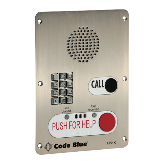
IP5000 2.0 Series Administrator Guide 2 Introduction Thank you for choosing the Code Blue IP5000 full duplex VoIP speakerphone, intercom and paging device for indoor and outdoor applications. This speakerphone is part of our Emergency Signaling group of products built to meet the latest regulations, withstand the harshest elements and be proactive solutions for when you need them most. This guide provides basic and advanced configuration information for obtaining the best performance with the IP5000 speakerphone. IP5000 Single Button IP5000 Dual Button IP5000 Dual Button w/ Keypad Code Blue 259 Hedcor Street Holland, MI 49423 USA 800.205.7186 www.codeblue.com page 3 of 61 GU-142-F • •... -
Page 4: Getting Started
IP5000 2.0 Series Administrator Guide 3 Getting Started This chapter provides information for obtaining the best performance with the IP5000 speakerphone. It is strongly recommended that the entire guide is read before configuring your IP5000 speaker- phone to ensure you get maximum performance. Throughout this guide you will see the following two references: Calling Party: This is the person activating the IP5000 speakerphone by pressing a button. Called Party: This is the person receiving the call from the IP5000; typically a guard, 911 operator, dispatch officer, etc. The IP5000 speakerphone provides powerful, yet flexible IP emergency communication, delivering excellent voice quality for your emergency speakerphone, intercom and paging solution. Code Blue 259 Hedcor Street Holland, MI 49423 USA 800.205.7186 www.codeblue.com page 4 of 61 GU-142-F •... -
Page 5: Connectors, Ports And Switch List
IP5000 2.0 Series Administrator Guide 4 Connectors, Ports and Switch List The IP5000 speakerphone comes with your choice of single button, dual button or dual button with keypad faceplate. The internal components consist of a speaker, microphone, PCB and mounting hardware. Code Blue 259 Hedcor Street Holland, MI 49423 USA 800.205.7186 www.codeblue.com page 5 of 61 GU-142-F • • • •... -
Page 6: Wiring Diagram/Poe Wiring Diagram
5 Wiring Diagram/PoE Wiring Diagram 802.3af / at Switch First, Electrical connection: All 3 Code Blue device’s should to be connected to the 5 place manifold Special Note: Notice the power cable is connected to the Battery / Alternative Power Cust port of the IP5000. -
Page 7: Installing The Ip5000 Speakerphone
IP5000 2.0 Series Administrator Guide 6 Installing the IP5000 Speakerphone The IP5000 speakerphone is capable of being connected to PoE (802.11af & at), 12-24 Volts AC or DC power sources. Additionally, the IP5000 may also be configured with a 12-Volt DC battery backup or alternative 12V DC power source system which monitors and reports low voltage condition for ensured up time. The IP5000 speakerphone has three Ethernet switch ports, one PoE LAN and two non-PoE LANS available for connectivity to network services and for additional network connectivity for auxiliary devices, such as IP cameras, card readers, etc. Additional LANS are not VLAN compatible. The IP5000 speakerphone has two normally open auxiliary output contacts for connecting devices such as the LED beacon/strobe, camera preset activation inputs, third party controllers, etc. There is also one normally open auxiliary input contact closure for connecting devices, such as door contacts, relays, etc., which can be programmed to perform any function of the phone. The IP5000 speakerphone has been designed to be mounted in any Code Blue enclosure. Custom faceplates are available for mounting in other product enclosures. Contact your local dealer for additional information and availability of custom options. Code Blue 259 Hedcor Street Holland, MI 49423 USA 800.205.7186 www.codeblue.com page 7 of 61 GU-142-F •... -
Page 8: Connecting Power Sources
IP5000 v2. IP5000 v2.0.0 Administrator’s Gu IP5000 2.0 Series Administrator’s Guide Administrator Guide 1-4 CONNECTING POWER SOURCES 1-4 CONNECTING POWER SOURCES 6.1 Connecting Power Sources The IP5000 speakerphone is capable of being connected to any power The IP5000 speakerphone is capable of being connected to any power source that provides 12-24 Volts AC or DC with a minimum of 430 mA source that provides 12-24 Volts AC or DC with a minimum of 430 mA The IP5000 speakerphone is capable of being connected to any current rating. Optionally 2.0Ahr battery can be connected to the current rating. Optionally 2.0Ahr battery can be connected to the power source that provides 12-24 Volts AC or DC with a minimum of secondary power input and the IP5000 speakerphone will monitor the secondary power input and the IP5000 speakerphone will monitor the 430 mA current rating. Optionally, a 2.0Ahr battery can be connected ® battery for low voltage conditions. When used in solar or NightCharge ®... -
Page 9: Installation Into Code Blue Units
IP5000 2.0 Series IP5000 v2.0.0 Administrator’s Guide Administrator Guide 6.4 Installation into Code Blue Units 1-7 INSTALLATION INTO CODE BLUE UNITS The IP5000 speakerphone is designed to fit into any existing or new Code Blue unit enclosure. It The IP5000 speakerphone is designed to fit into any existing or new Code Blue unit enclosure. It is a direct is a direct replacement for the InterAct analog series: IA2000, IA3000, IA3100, IA4000 and IA4100. replacement for the InterAct analog series: IA2000, IA3000, IA3100, IA4000 and IA4100. Additionally, Code Blue Additionally, Code Blue offers custom faceplate designs that allow the IP5000 to be placed in offers custom faceplate designs allowing the IP5000 to be placed in many different enclosure types. Code Blue many different enclosure types. Code Blue provides six custom security screws and security bits provides six (6) custom security screws and security bit with each Code Blue unit for attaching the IP5000 with each Code Blue unit for attaching the IP5000 speakerphone. Consult your unit installation speakerphone. Consult your unit installation instructions for further information. instructions for further information. Page 7 Code Blue 259 Hedcor Street Holland, MI 49423 USA 800.205.7186... -
Page 10: Optional Flush Mount Enclosure Installation Instructions
IP5000 2.0 Series Administrator Guide 7 Optional Flush Mount Enclosure Installation Instructions PRE-INSTALLATION Electrical preparation – The unit may have supply wires run from either (a) behind the unit through the wall, or (b) below the unit by using an external conduit through the bottom of the unit’s back plate. Mounting holes in the back, bottom or side of unit to be administered by the installer. IMPORTANT: If wiring is coming in from the bottom or back, insure that the conduit is aligned at this time. Connect electrical and communications wiring (see wiring instructions). Follow all national and local codes that apply. Prepare Wall – FME enclosure mounting hole in wall should except the housing dimensions below and must be smaller than the faceplate dimensions to ensure clean flush mount look. INSTALLATION PROCEDURES Mark the flush mount mounting hole – In order to comply with the Americans with Disabil- ities Act (ADA) of 1990, the speakerphone button(s) should be positioned between 34 and 48 inches from grade level. (Consult an ADA specialist in your area to verify local and federal guidelines.) Secure the housing to the wall – The Flush mount enclosure can be mounted from the back, bottom or side by drilling the mounting holes where needed per the installers application while still keeping the unit within ADA compliance height. (1.2) Mounting hardware to be supplied by in-... -
Page 11: Using The Ip5000 Speakerphone
IP5000 2.0 Series Administrator Guide 8 Using the IP5000 Speakerphone The IP5000 speakerphone can be configured for multiple uses. The main function is to provide two- way voice communications. Pressing button #1 (Red button) PUSH FOR HELP, EMERGENCY or EMERGENCY/EMERGENCIA will activate the configured script programmed for button #1. Button #1 activation overrides any other action the IP5000 is performing at the time of the button press. For example, if the IP5000 was: 1. Being programmed at the time 2. In a monitoring call 3. In the middle of a diagnostic test 4. In the process of a Public Alert session 5. In an information (button #2) call. Button #2, INFO or CALL, are typically utilized for placing informational calls or for acquiring dial tone and utilizing the keypad, respectively. Any action other than button #1 activation is considered... -
Page 12: Network Setup - Setting A Static Ip Address
IP5000 2.0 Series Administrator Guide 9 Network Setup Determine the IP Address The IP5000 speakerphone is DHCP by default. 1. Connect the IP5000 speakerphone to your network. The LED will flash momentarily and an audible beep will be heard out of the speaker to indicate the OS is loading. The IP5000 speakerphone will acquire IP Network settings from your DHCP server. 2. Check your DHCP lease records or utilize a network scanner such as SoftPerfect’s Network Scanner to match the MAC address of the IP5000 speakerphone to the correct IP address in your lease table or output of the network scanner. Lease Table and Network Scanner Example Code Blue 259 Hedcor Street Holland, MI 49423 USA 800.205.7186 www.codeblue.com page 12 of 61 GU-142-F •... -
Page 13: Provisioning The Phone
IP5000 2.0 Series Administrator Guide 10 Provisioning the Phone 10.1 Setting a Static IP Address Once you have obtained the DHCP address of the IP5000 and are logged in to the speakerphone, you have the option of leaving the speakerphone set at DHCP (default setting) or setting a static IP address. To set a static IP address: 1. Click on the Network menu item under Network Setup (see far left-hand column). 2. Under the General section, select Static IP as the Connection Type. 3. Enter your desired IP settings under the Static IP Address heading. -
Page 14: Logging Into And Out Of The System
IP5000 2.0 Series Administrator Guide 10.2 Logging into and out of the System Logging into the System 1. Log in using a web browser. A. Place the IP Address of your IP5000 into the URL address bar and press ENTER. B. Depending on the browser being used, a certificate warning may pop up. Go ahead and approve in order to load the login dialog box. C. Enter user name “admin” and password “admin” and press ENTER. 2. System Status Screen. A. Current session time before Auto-Logout is executed. B. Clicking Renew will restart the timer to 10 minutes, effectively keeping you logged in. This state helps prevent others from logging in and taking over the session, therefore erasing any unsaved changes made. - Page 15 IP5000 2.0 Series Administrator Guide Logging into the System 1. To log out of the IP5000 speakerphone, simply click on Logout under Session (see far left- hand column). The speakerphone will also log you out automatically after 10 minutes. You will be prompted for confirmation. 2. Click OK to complete the logout process or Cancel to continue configuring your IP5000. Code Blue 259 Hedcor Street Holland, MI 49423 USA 800.205.7186 www.codeblue.com page 15 of 61 GU-142-F • • • •...
-
Page 16: Network Configuration
IP5000 2.0 Series Administrator Guide 10.3 Network Configuration Once you have obtained the DHCP address of the IP5000 speakerphone, you can log in and set a static IP address. 1. Click on the Network menu item under Network Setup (see far left-hand column). 2. Under General, click on Static IP for Connection Type. 3. Enter your desired IP settings under Static IP Address. 4. Once you have entered your settings, click on Save Changes. Note that if you have moved your IP5000 to a network your PC cannot access, you will have to con- figure your PC to access that network before configuration can continue. Code Blue... - Page 17 IP5000 2.0 Series Administrator Guide VLAN Configuration The IP5000 speakerphone is capable of performing IEEE 802.1Q frame tagging and user priority settings. 1. Click on the Network menu item under Network Setup (see far left-hand column). 2. Then click on the VLAN Enabled check box in the VLAN section and select your desired VLAN ID and User Priority. 3. Once you have entered your settings, click on Save Changes. Note that if your PC cannot access the new VLAN, you will have to correct this problem before continuing configuration, as you will lose access to the IP5000. If you wish to disable VLAN support and cannot reach the IP5000 on its configured VLAN, factory-reset the unit to clear network configu- ration. Code Blue...
-
Page 18: Configuring The Ip5000 Voip Settings
IP5000 2.0 Series Administrator Guide 10.4 Configuring the IP5000 VoIP Settings The IP5000 speakerphone is an advanced VoIP device capable of connectivity to VoIP systems via SIP and IAX2 protocols. Built-in codecs provide multiple options for communicating with your VoIP system or Code Blue’s ToolVox Media Gateway. STUN server capabilities are also built-in for help- ® ing traverse firewalls when connecting the unit outside of the hosting network. CONFIGURING VOIP ACCOUNTS The IP5000 speakerphone can register to VoIP systems using either the SIP or IAX protocols, and has the ability to register to two separate VoIP systems simultaneously to provide redundancy. Each of the IP5000’s two accounts, available under VoIP Setup as Account 1 and Account 2, can be configured as either SIP or IAX, subject to the limitation that you can only have one of the two ac- counts configured as IAX. If you wish to use only one account, set Account 2 to Disabled. Code Blue 259 Hedcor Street Holland, MI 49423 USA 800.205.7186 www.codeblue.com page 18 of 61 GU-142-F •... - Page 19 IP5000 2.0 Series Administrator Guide Configuring a SIP Account Either of the IP5000 speakerphone’s two accounts can be configured to register to a VoIP system via SIP. Configuration is as follows: • Set the VoIP Protocol to SIP and RTP. • For Description, enter a name the IP5000 will use internally to refer to this account. • For Username/Number, enter the number that the IP5000 will use for SIP addressing. This will often be the extension number in a VoIP-based PBX. • For Display Name, enter the name the IP5000 will send in SIP transactions. This will often be the calling name of the extension. • For Domain, enter the domain the IP5000 will register to. • For Outbound Proxy, enter a SIP proxy the IP5000 should send outbound calls to. If this is the same as the domain, you can leave this field blank. • For Outbound Proxy Port, enter an IP port number the IP5000 will send outbound calls to. Typi- cally, this should be left at 0. • For Registration Lifetime, enter the time in seconds the IP5000 will request that its registration be valid for. The IP5000 will automatically re-register before this time period expires. • Check Keep-Alive if you want the IP5000 to periodically send OPTIONS requests to the SIP server, e.g. to keep a NAT connection alive. • Check STUN if you want to enable STUN support for this account. • You can adjust the DTMF Threshhold value if you have difficulties with the IP5000 activating in- call commands when no DTMF is present.
- Page 20 IP5000 2.0 Series Administrator Guide Configuring an IAX Account Either of the IP5000 speakerphone’s two accounts can be configured to register to a VoIP system via IAX. (Note, however, that only one of the two accounts may be configured as IAX - the IP5000 does not support two simultaneous IAX accounts.) Configuration is as follows: • Set the VoIP Protocol to IAX. • For Description, enter a name the IP5000 will use internally to refer to this account. • For Username/Number, enter the number that the IP5000 will use for IAX addressing. This will often be the extension number in a VoIP-based PBX. • For Display Name, enter the display name the IP5000 will send in IAX transactions. This will often be the calling name of the extension. • For Domain, enter the domain the IP5000 will use in its IAX address. • For Registrar, enter the address of the IAX server the IP5000 should register and send outbound calls to. If this is the...
- Page 21 IP5000 2.0 Series Administrator Guide Configuring Media Settings For the SIP protocol, you can specify a port range from which the IP5000 will select IP ports to offer to the other system for use with RTP communication. The IP5000 speakerphone can use any one of a suite of codecs for voice communication. Which co- dec is used is dependent on negotiation with the remote system, but you can use Codec Selection to specify a list of preferred codecs that will be offered in negotiation. • To add codecs to the Preferred list, highlight them in the Available list and click Add. • To remove codecs from the Preferred list, highlight them and click Remove. • To change the order preferred codecs are offered, highlight them and click either Move Up or Move Down to reorganize them. Note that some codecs corrupt DTMF tones, e.g. G.729. If RFC2833 out-of-band DTMF signaling is not in use, be sure to configure your codecs appropriately or you may not be able to use in-call com- mands. Be sure to test your configuration to make sure all features are available. Code Blue 259 Hedcor Street Holland, MI 49423 USA 800.205.7186 www.codeblue.com...
- Page 22 IP5000 2.0 Series Administrator Guide Configuring Advanced Settings The IP5000 speakerphone can be configured to utilize a STUN server for transversal of firewall devices for the setup of a VoIP call. 1. Click on Advanced under VoIP Setup (see far left-hand column) to configure the STUN server IP address and Port. 2. Upon completion, click Save Changes. Code Blue 259 Hedcor Street Holland, MI 49423 USA 800.205.7186 www.codeblue.com page 22 of 61 GU-142-F •...
-
Page 23: Configuring The System Settings
IP5000 2.0 Series Administrator Guide 10.5 Configuring the System Settings IP5000 speakerphone system administration is provided under the System Settings dialog, which allows you to change the following: • Administrative Logon Credentials • Syslog Service Reporting • Secure HTTP Server • Date and Time • Upgrade Firmware Code Blue 259 Hedcor Street Holland, MI 49423 USA 800.205.7186... - Page 24 IP5000 2.0 Series Administrator Guide System Administration Settings The Administration page under System contains several settings: • System Info displays the MAC address and firmware version running on the IP5000. • Administrator allows the administrator username and password to be changed. Enter a new Username, if desired, and enter the new Password and again in the Confirm box to change these parameters. • The IP5000 can send RFC 5424 Syslog messages to a Syslog server by specifying it in this section. Note that Syslog messages are only useful for advanced troubleshooting and are not intended for general monitoring. • A new private key and certificate can be uploaded to the IP5000’s Secure HTTP Server if you do not wish to use the system’s built-in key and certificate. The key should be PKCS#8, DER- formatted and the certificate X.509, DER-formatted. When you are finished , click Save Changes. You can also reboot the device directly from this page by clicking Reboot Now.
- Page 25 IP5000 2.0 Series Administrator Guide Date and Time Configuration The IP5000 speakerphone date and time are managed by: 1. Clicking Date/Time under System (see far left-hand column). Under Set Date & Time, you can manually set the Date, Time, Daylight Savings (if applicable) and Time Zone. 2. To automatically synchronize with an NTP (Network Time Protocol) server, check Enabled and enter the IP or URL of the NTP server (i.e. Server Address). 3. Click Save Changes. Code Blue 259 Hedcor Street Holland, MI 49423 USA 800.205.7186 www.codeblue.com page 25 of 61 GU-142-F •...
- Page 26 IP5000 2.0 Series Administrator Guide Upgrading the IP5000 Firmware The IP5000 speakerphone firmware file can be changed by: 1. Select Upgrade Firmware under System (see far left-hand column). 2. Click Browse (or Select File) and select the appropriate firmware file. 3. Click the Upgrade button. 4. The IP5000 speakerphone will update, automatically back up the new firmware and reboot. Once this is complete, your new firmware will be in use and should be displayed next to Current Version. Note: Firmware version is also reported in the Administration section. Code Blue 259 Hedcor Street Holland, MI 49423 USA 800.205.7186 www.codeblue.com...
-
Page 27: Configuring System Options And Scripts
10.6 Configuring System Options and Scripts The IP5000 speakerphone has advanced configuration settings that allow for complete control of the hardware and how the system performs. A memory capacity of 3 MB provides multiple phone numbers and recorded message capabilities. Incoming call routing, SNMP and advanced diagnos- tics enhanced with advanced scripting capabilities provide for flexible configurations. Batch Configuration The IP5000 speakerphone can be configured from a TFTP server, e.g. UPD. Click on Batch Configuration under Code Blue (see far left-hand column) Enter the TFTP Server IP address and TFTP Server Port. Click on Fetch Configuration to pull the configuration files from your TFTP server. Click on Verify Integrity to validate the configuration files are suitable for use. This functionality can be used in lieu of UPD’s program functionality to have the IP5000 pull its con- figuration instead of having it pushed from UPD. Code Blue 259 Hedcor Street Holland, MI 49423 USA 800.205.7186... - Page 28 IP5000 2.0 Series Administrator Guide Entering Phone Numbers The IP5000 speakerphone number configuration is made by: 1. Clicking Numbers under Code Blue (see far left-hand column). 2. Enter the extension (i.e. SIP account, user extension). Choose which account this extension number will be related to, then enter a description for this extension. See account reference on page 11. 3. Select the green plus sign to add the number. 4. To delete a number simply click the red X. 5. Select the green check mark when prompted, Are you sure? Code Blue 259 Hedcor Street Holland, MI 49423 USA 800.205.7186...
- Page 29 IP5000 2.0 Series Administrator Guide Recording Administration The IP5000 speakerphone recording configuration is made by: 1. Selecting Recordings under Code Blue (see far left-hand column). 2. Click on Select recording file, choose the file you wish to upload to the IP5000 and click Open. 3. Enter the Description within the Description Field. 4. Click on the green plus sign to add the recording and wait for it to finish. During the upload process the screen will display, Uploading file… At this point do not refresh the page or click away from the page or the file will not be uploaded. Once the file upload is complete, you will see Download Recording and a new line for uploading additional recordings.
- Page 30 IP5000 2.0 Series Administrator Guide Hardware Settings The IP5000 speakerphone hardware settings are configured by: 1. Selecting Hardware Settings under Code Blue (see far left-hand column). 2. Select the appropriate Button Count, Keypad Available and Public Address Available settings under the Interface section. Public Address Available is utilized when the IP5000 is controlling the optional Code Blue PAS components (i.e. CB 1, CB 2, CB 5 with Public Address or WM180). 3. The Power Sources section allows you to select the power sources connected to the IP5000. Note: By default, A/C is selected. If the IP5000 power source is solely PoE, failure to un check the A/C Box will result in SNMP traps noting the failure of A/C, when in fact there is no A/C power applied. 4. Checking Aux Output 1 or 2 will enable the auxiliary output relay. By default, the port is set to enable (Toggle State) when used in an Action Script. When momentary toggle has been selected, the called party now has the ability to activate the auxiliary output remotely for the time period chosen via DTMF tones, from their phone’s keypad.
- Page 31 IP5000 2.0 Series Administrator Guide General Settings The IP5000 speakerphone general configuration can be accessed by: 1. Clicking on General Settings under Code Blue (see far left-hand column). In this section you can select how many rings the IP5000 will wait before answering an incoming call. 2. Click the down arrow next to Answer In to change settings. 3. Additionally, to route all incoming calls to the PAS line level audio output for mass notification, check the box (i.e. Always route incoming calls to public address) next to Public Address. When checked, Auxiliary Output 1 and 2 check boxes will enable the A/O 1 & 2 on incoming call and is disabled when incoming call is terminated. This feature was not intended to be used with Auxiliary Outputs configured with the momentarily (Hardware Settings Dialog) choice. The IP5000 can also be configured with a standard location message. 1. Click on the down arrow next to Location Recording to select this recording as the default Location Message.
- Page 32 IP5000 2.0 Series Administrator Guide Action Script Configuration Action Scripts are based on Hardware Settings made earlier in the setup process. For example, if your IP5000 has two physical button, and only one was selected in Hardware Settings “Interface” “Button Count,” some scripts choices will be missing. Scripting Requirements The Action Script in the IP5000 can be very extensive, yet only if all the correct features are enabled. Understanding all the abilities of the phone is required. Only then can the user configure the IP5000 for maximum functionality. Numbers: Load phone numbers for all of your planned calls from this IP5000. Recordings Record all message and upload them to this IP5000. Hardware Settings Ensure the IP5000 features are represented in the Hardware Settings portion of the GUI. Diagnostic Settings When using remote monitoring services, for example, SNMP Server service or Code Blue’s ToolVox Server w/UPD application, the IP5000 will send SNMP traps or use the “Action Scripts” ® generate calls to a monitoring service and play pre-recorded messages as a notification when an issue has been detected. Scripting Basic Call The IP5000 has GUI interface for building scripts. Scripting can consist of a single action or combination of actions related to a button press or Auxiliary Output Trigger alone.
- Page 33 IP5000 2.0 Series Administrator Guide Scripting Basic Call (continued) SCRIPTING BASIC CALL (continued) • From the Select Action drop down, choose Place Call. SCRIPTING BASIC CALL • From the Select Action drop down choose Place Call. (continued) • From the Select Action drop down choose Place Call. • By default, the first number placed in memory • By default the first number placed in memory will be present here. If another number is desired, use the drop-down arrow will be present here. If another number is...
- Page 34 IP5000 2.0 Series Administrator Guide Scripting Basic Call SCRIPTING BASIC CALL (continued) (continued) 4. The next choice is to Enable this Aux Output and/or set the Duration for this Aux Output 4. Next choice is to Enable this Aux Output and or set the Duration for this Aux Output Action. In this example let’s Action. In this example, let’s request a 10-second duration upon the touch of button #1.
- Page 35 IP5000 2.0 Series Administrator Guide Action Script Parameters Within the Scripts are many settings controlling the next step in the process of the Action Script: • Duration of the process • Enable / Disable features • A reactivation of an Aux Output with a timed limitation ACTION SCRIPT PARAMETERS The following will provide detailed explanations into these Script controls. Within the Scripts are many settings controlling the next step in the process of the Action Script: Duration of the process, Enable / Disable features, or even a reactivation of an Aux Output with a timed limitation. The following will Note: Scripts, Phone Numbers, and Recordings all share a 1MB memory cap.
- Page 36 IP5000 2.0 Series Administrator Guide Action Script Parameters (continued) ACTION SCRIPT PARAMETERS (continued) Place Call When Answered: The default setting is (continued) Normal Two-Way Conversation. The option is to Play Custom Messages. A message can be set to play Locally (at the IP5000) or Remotely (to the Called Party). Choosing this option will add another option to the Place call sequence, And Then. The And Then choice allows the call to...
- Page 37 IP5000 2.0 Series Administrator Guide Auxiliary Output Expanded Functionality and Use Case The IP5000 Auxiliary Output abilities have been expanded for unique use cases: Security Personal Access Controls. Example: Gate or Door Control Either output can be configured to activate upon the called party’s use of DTMF keys 4 or 5 on the phone for a predetermined time period by the Gate Mechanism (example - four seconds). 1. Setting up Auxiliary Output 1 to Momentarily Toggle for four seconds: Aux Output Momentary Toggle is best used for remote control operations and should not be com- bined with Scripted Timed Aux Output timers or Incoming Calls > Aux Output > Enable when an Incoming Call is active.
- Page 38 IP5000 2.0 Series Administrator Guide Auxiliary Input Activated Scenario In this example, the IP5000 has been configured to perform the following Script upon an Auxiliary Input Contact Closure: 1. Play a Message out of the speaker. 2. Trigger Aux Output #1 (strobe light). 3. Place a Call to “Security” A. Upon connecting, activate Aux Output #2 until remotely released by the Called Party (Security). B. Release for Aux Output #2 is accomplished by the Called party’s phone keypad – Key #5. 4. Called Party disconnects. Disable Aux Output #1 (strobe light) 20 seconds after the Called Party hangs up. Code Blue 259 Hedcor Street Holland, MI 49423 USA 800.205.7186 www.codeblue.com page 38 of 61 GU-142-F •...
- Page 39 Public Address – PAS System Administrator Guide Public Address – PAS System If your IP5000 is connected to a Code Blue PAS speaker system, If your IP5000 is connected to a Code Blue PAS speaker system, configure the below. Public Address configure the below.
- Page 40 IP5000 2.0 Series Administrator Guide CONFIGURING DIAGNOSTICS Diagnostic Settings The IP5000 speakerphone diagnostic settings are configured by: • Selecting Diagnostic Settings in the Code Blue Configuration. • Click the Enable check box. • Input the SNMP Server IP address and SNMP Server Port number to monitor the IP5000 with an SNMP management software or with Code Blue’s ToolVox Gateway, w/Unit Programming & ® Diagnostic (UPD) Software. Power Supply Failure Timeout The IP5000 monitors the power sources for loss of power or, in the case of the 12Volt / Battery, the circuit monitors for Low Voltage condition(11.5 – 11.0V). Note: Backup power must be available for the phone to report a power failure. If no power is available, a network management system must periodically check the phone for the power failure to be reported. Code Blue’s UPD can provide this function. • Power supply monitoring is based on the selections made in Hardware Settings > Power Supply section. • 12-24 Volt A/C or D/C monitoring will be checked within the time interval provided. (Example: 900 seconds = 15 minutes.) The interval range 0 - 9999999 (1 second - 2,777.7775 hours), should the voltage become unavailable or a problem has been detected. The CODEBLUE- MIB::powerSource parameter will be issued. • Main power MIB value is CODEBLUE-MIB::powerSource.0 ac. The SNMP trap will be issued again if at the next interval the voltage issue has not been rectified within the timed interval another Trap will be sent. The AC power failure script will also be run.
- Page 41 IP5000 2.0 Series Administrator Guide Others – (Tests) Microphone testing is disabled by default. Enabling will show a number of reoccurring test routines. The microphone is supported by the speaker’s ability to generate tones at the schedule intervals. • The test consists of beeps from the speaker, which will be received by the microphone. » The maximum number of beeps: 2 - 10 beeps. Once the microphone detects the beeps, the test is complete until the next scheduled test is present. » The beep tone volume choices are soft, loud, or soft to loud. The beep tone volume setting should be set to anticipate ambient noise level at the time of the test. The test schedule choices are: • Every 15 minutes • Hourly • Daily • Weekly • Testing on demand: When microphone speaker testing is enabled, the administrator may select to Run Test while logged into the IP5000. The results of the test will only be present in a failed SNMP trap, which would appear in the SNMP server logs or UPD Diagnostic Reports logs. The MIB value is CODEBLUE-MIB::micSpeakerFailure.
-
Page 42: Dual Accounts
IP5000 2.0 Series Administrator Guide 11 Dual Accounts Sample Application using Dual Accounts on the IP5000 phone If using both accounts on an IP5000, you must set up two numbers (one “via Account 1” and the other “via Account 2”), and an action script with a single dial step with “call first number” and “if not answered then call second number”. Use outcomes dependent on the network: 1. If server 1 is considered registered and responds, the call goes through to server 1 immediately. 2. If server 1 is considered registered and unresponsive, it will be tried for up to Dialing/ answer timeout, but no more than 30 seconds. Then server 2 will be tried. 3. If server 1 is not considered registered, server 1 will be skipped and server 2 will be tried immediately. Code Blue 259 Hedcor Street Holland, MI 49423 USA 800.205.7186... -
Page 43: Cli (Command Line Interface)
IP5000 2.0 Series Administrator Guide CLI (Command Line Interface) 12 CLI (Command Line Interface) The IP5000 has extensive commands that can be used by telnetting into the device. The IP5000 has extensive commands that can be used by telnetting into the device. You can use windows telnet or download a common free telnet client, “putty”. You can use windows telnet or download a common free telnet client, “putty”. -
Page 44: In-Call Commands
IP5000 2.0 Series Administrator Guide 13 In-Call Commands The IP5000 speakerphone provides enhanced functionality through the utilization of In Call Commands. These commands are DTMF or phone keypad entries made by the Called Party. Below is a list and explanation of each command. In-Call Command Function Description Play Location Message Plays the Location Recording selected in General Settings Switch from Speaker to PAS Transfers the audio to the PAS audio output Output and Mute the Mic and mutes the microphone to eliminate a feedback loop Deactivate Call Timer Deactivates the Maximum call duration timer setting in the operational script currently running Activate/Deactivate Auxiliary 1 Toggle Auxiliary 1 state; activate or deactivate Activate/Deactivate Auxiliary 2 Toggle Auxiliary 2 state; activate or... -
Page 45: Factory Reset
IP5000 2.0 Series Administrator Guide 14 Factory Reset The system can be reset via two different methods. First Method: Press the reset button for five seconds and it will delete the IP5000 network config files; scripts and recordings will remain. Press reset button for 10 seconds or more and the IP5000 file system will be formatted resetting to factory defaults. (Continued on next page) Code Blue 259 Hedcor Street Holland, MI 49423 USA 800.205.7186 www.codeblue.com page 45 of 61 GU-142-F •... - Page 46 IP5000 2.0 Series FACTORY RESET (continued) Administrator Guide Method: If you have telnet access to the unit, you can default the unit through the command line Factory Reset (continued) interface. Second Method: You can use windows telnet or download a common free telnet client, “putty”. If you have telnet access to the unit, you can default the unit through the command line interface. Telnet to the IP Address of the IP5000 phone: use port 23 if unsure You can use windows telnet or download a common free telnet client, “putty”.
-
Page 47: Compatibility
IP5000 2.0 Series Administrator Guide 15 Compatibility The IP5000 phone is a SIP version 2.0 (RFC3261) device and is compatible with IP Gateways and PBXs that can register third Party SIP devices to them. You must verify that the IP PBX you are registering the IP5000 to can handle Third Party SIP devices, whether through licensing and/or Hardware add-ons. -
Page 48: Configuring For Cisco Unified Communications Manager 9
IP5000 2.0 Series Administrator Guide 16 Configuring for Cisco Unified Communications Manager 9 PREPARATION 1. Record the MAC address and determine the current IP address for each IP1500/2500/5000 device you wish to use with CUCM. 2. Determine which partition you will put the IP1500/2500/5000 directory numbers into. 3. Obtain one directory number for each IP1500/2500/5000 device. a. If you are going to use the IP1500/2500/5000’s dual account configuration to regis ter to redundant CUCM servers, obtain a second directory number for each IP1500/2500/5000 device. 4. Determine which calling search space you will assign to the IP1500/2500/5000. UCM CONFIGURATION All UCM-side configuration is done within the Cisco Unified CM Administration web interface. Create Phone Security Profile 1. Navigate to System > Security > Phone Security Profile. 2. Do a Find on “Third-party” to locate the Third-party SIP Device Basic - Standard SIP Non- Secure Profile. C lick the Copy icon. - Page 49 IP5000 2.0 Series Administrator Guide 5. Create and record a secure SIP password and fill in the Digest Credentials and Confirm Digest Credentials fields with this password. You will be entering this password later into the IP1500/2500/5000. 6. Click Save. Configuring End Users for Secondary Accounts If you are going to use the IP1500/2500/5000’s secondary account functionality to register to a separate directory number to a separate CUCM node for failover support, repeat the above process using a local-use-only MAC address. A local-use-only MAC address has the U/L bit set to 1 to indi- cate the address is locally administered. Since all IP1500/2500/5000 units’ MAC addresses start with 0, you can create a locally-administered address that is unlikely to conflict with other locally-administered addresses simply by setting the U/L bit simply means changing the second 0 to a 2, e.g. 0250c2177be8. Configure Phones and Directory Numbers For each IP5000 device, configure a new Phone and associated directory number. 1. Navigate to Device > Phone.
- Page 50 IP5000 2.0 Series Administrator Guide 15. Under Line 1, for Display (Internal Caller ID), enter a descriptive name for Caller ID pur poses. 16. If you wish to return a busy signal for silent monitoring if the IP1500/2500/5000 is in use, disable Call Waiting: under Multiple Call/Call Waiting Settings, For both Maximum Number of Calls and Busy Trigger, enter 1. 17. Click Save. Configuring Phones and Directory Numbers for Secondary Accounts If you are going to use the IP1500/2500/5000’s secondary account functionality, repeat the above process with a local-use-only MAC address as outlined in Configuring End Users for Secondary Ac- counts, and specify a distinct directory number. IP5000 CONFIGURATION Refer to the IP1500/2500/5000 Administration AND User Guide located on our website Clear Existing Configuration If necessary, clear the IP1500/2500/5000’s existing configuration. This will reset it to DHCP, so make sure you have the capability to find the device’s IP address again if you do this. For each unit: 1. Open a Telnet client and connect to the IP1500/2500/5000. 2. Log in using the username admin and the default password admin. 3. Type format c: codeblue and press Enter.
-
Page 51: Other Settings
IP5000 2.0 Series Administrator Guide 7. Insure Keep-Alive is enabled. 8. Under Proxy Authentication, for Username, enter the username you assigned the CUCM end user, e.g. the hexadecimal representation of the MAC address or the local-use variant for a secondary account. 9. For Password, enter the password you entered into Digest Credentials under the CUCM end user. 10. Click Save. 11. Repeat steps 3-10 with Account 2 if you are using the second account. Other Settings Refer to the IP1500/2500/5000 Administration AND User Guide to complete the setup of the IP1500/2500/5000, including Numbers, General Settings, Hardware Settings, and Action Scripts. When finished, click Apply Now to restart the phone; it should now register to CUCM and be able to place calls in the assigned calling search space as well as receive calls at the directory number it is configured with. Note: if you are setting up the IP1500/2500/5000 with secondary account support, make sure that you create each failover number twice. -
Page 52: Avaya Ip Office Integration Guide
IP5000 2.0 Series Administrator Guide 17 Avaya IP Office Integration Guide Introduction This Avaya IP Office Integration Guide provides general instructions for integration of the IP1500/2500/5000 Series Phones with an IP Office installation. Read this instruction set completely before starting any installation. For detailed IP1500/2500/5000 setup instructions, please consult the IP1500/2500/5000 Guides. Prerequisites • Avaya IP Office Manager Version 9 pre-installed • SIP Device Licensing for 3rd Party IP Endpoints • Network access to the IP Office Manager, IP1500/2500/5000 Series Phones and all network services (SIP, HTTP, FTP, RTP/SRTP) IP Office Manager Basic Configuration Basic instructions for integrating IP1500/2500/5000 Series Phones with an Avaya IP Office R7 Manager are included. Advanced setup of IP Office Manager features is outside the scope of this... - Page 53 IP5000 2.0 Series Administrator Guide 2. Log in to Avaya IP Office Manager: IP1500/2500/5000 3. SIP Extension Support is required for integration. Select System > LAN1 (or LAN2) > VoIP in IP Office Manager: Code Blue 259 Hedcor Street Holland, MI 49423 USA 800.205.7186 www.codeblue.com page 53 of 61 GU-142-F • • • •...
- Page 54 IP5000 2.0 Series Administrator Guide SIP Registrar Enable 4. Check that is enabled. SIP Registrar 5. Select the sub-tab. Domain Name, 6. In enter the Fully Qualified Domain Name (FQDN) or the IP ad dress associated with the correct LAN port on the IP Office Control Unit. Deselect Auto-create Extn/User. Click Code Blue 259 Hedcor Street Holland, MI 49423 USA 800.205.7186 www.codeblue.com page 54 of 61 GU-142-F •...
- Page 55 IP5000 2.0 Series Administrator Guide IP1500/2500/5000 Series Phone 7. A SIP extension will need to be created for each Extension SIP Extension Right click on , select and then click on 8. Enter the following fields to create a new extension: Extension ID: • A unique extension to identify the logical extension in IP Office. By default, IP extensions start at 8000. Base Extension: IP1500/2500/5000 Series • This is the extension used to call the...
- Page 56 IP5000 2.0 Series Administrator Guide VoIP Compression Mode 9. Select the tab and select the . The default of the IP1500/2500/5000 Series Phone G.711 U-LAW and will work in most cases. IP1500/2500/5000 Series More information on audio codecs can be found in the Phone Guides DTMF Support to RFC2833. . Set IP1500/2500/5000 Series Phone Each should have a unique User.
- Page 57 IP5000 2.0 Series Administrator Guide Enter the following fields to create a new user; Name: • This will be displayed as the user’s name in IP Office Manager, and is used as the username for SIP registration when configuring the IP1500/2500/5000 Series Phone Extension: Base Extension • This should match the configured for the SIP exten- sion in Step 8. This is also used as the phone number when configuring the IP1500/2500/5000 Series Phone Telephony Call Settings Call Select the tab and then the sub-tab. Disable Waiting On Answer Call Waiting on Hold . Call waiting is not supported on...
- Page 58 IP5000 2.0 Series Administrator Guide Supervisor Login Code Select the sub-tab. In the field enter a password to be IP1500/2500/5000 Series Phone used by the for authentication. Avaya IP Office will only accept numbers in this field. IP1500/2500/5000 Series Phones If adding multiple , repeat Steps 7-13 for each device. Code Blue 259 Hedcor Street Holland, MI 49423 USA 800.205.7186 www.codeblue.com page 58 of 61 GU-142-F •...
-
Page 59: Troubleshooting
IP5000 2.0 Series Administrator Guide 18 Troubleshooting the IP5000 Speakerphone The IP5000 speakerphone is a network device. The following are tips for troubleshooting: Power - Ensure the power to your device is working and rated for 802.11af/at PoE specifications if using POE. The IP5000 should only have one source of power other than a backup battery. If not using POE, then main power needs to fall into 12-24 Volts AC or DC. Ping Test - This determines connectivity and the packet loss and latency time to and from your destination and the quality of your network connection to the IP5000. If you receive no response and power is confirmed, contact your network administrator. You can also Ping from within the phone towards your IP PBX to test that it can reach its IP PBX/SIP Gateway. Network – If you’re putting the IP5000 on a network that restricts ports then the below ports must be open for the IP5000 to communicate to its appropriate IP PBX/SIP Gateway. 1. IAX2/UDP outgoing to port 4569 on IP PBX/SIP Gateway (only needed if using IAX2 instead of SIP on the accounts page). 2. SIP/UDP outgoing to port 5060 IP PBX/SIP Gateway. 3. RTP/UDP incoming from IP PBX/SIP Gateway to UDP ports 23456-23556 (configurable). DHCP - The IP5000 is setup for DHCP by default. If you cannot determine the IP address of your IP5000, contact your network administrator. Account - Ensure your SIP or IAX2 account is set up correctly. Account username and password must match the account credentials on your VoIP system. This is the most common mistake with setting up SIP accounts. Codec - Ensure the codec settings on your VoIP system match the IP5000 codec settings. Firewall - Firewalls commonly block or partially block VoIP calls. Check with your network administrator if you cannot communicate with your IP5000 from behind a firewall. Contact info for Code Blue Technical Services and Support staff can be located at the end of this Guide if you need further assistance troubleshooting your IP5000 phone. Depending on your issue, a firmware upgrade may be needed. Note: If you do not have a DHCP server running, use a standard home/wireless router and plug your speakerphone and laptop into the same router. Once you know the IP Address, you can browse to it... -
Page 60: Regulatory And Warranty
IP5000 2.0 Series Administrator Guide 19 Regulatory & Warranty Regulatory The IP5000 speakerphone conforms to the following list of directives and product safety standards as applicable: EU: EN 55022:2006+A1:2007 EN 55024:1998+A1:2001+A2:2003 EN 61000-4-2:1995 EN 61000-4-3:2006+A1:2008 EN 61000-4-4:2004 EN 61000-4-5:2006 EN 61000-4-6:2007 EN 61000-4-8:1993+A1:2001 EN 61000-4-11:2004 EN 61000-3-2:2006+A1:2007 EN 61000-3-3:2008 USA: CFR 47, Part 15... -
Page 61: Technical Services And Support
IP5000 2.0 Series Administrator Guide 20 Technical Services and Support For additional support, please feel free to contact Code Blue’s Technical Services and Support Staff at ts@codeblue.com or (616) 392-8296, Opt 3. 8 a.m. to 5 p.m. Monday through Friday Eastern Time Code Blue 259 Hedcor Street Holland, MI 49423 USA 800.205.7186 www.codeblue.com page 61 of 61 GU-142-F •...
Need help?
Do you have a question about the IP5000 2.0 Series and is the answer not in the manual?
Questions and answers