
Related Manuals for Genie CCTV Raptor II Ruggedized PTZ


Summary of Contents for Genie CCTV Raptor II Ruggedized PTZ
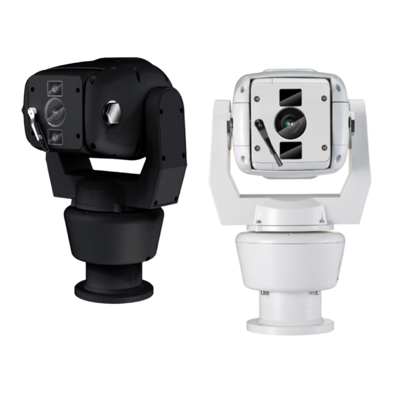
- Page 1 RPT36M SERIES Raptor II Ruggedized PTZ Instruction Manual Version 3.1 Please read this manual carefully before installation and operation of the product.
-
Page 2: Table Of Contents
Table of Contents INTRODUCTION 4 SAFETY WARNING 5 PACKING LIST 6 4. MOUNTING 8 • Mounting Options (UK Column Mounting) • Offset Mounting • Changing the Wiper • 14 Pin Cable Connection 5. TELEMETRY CONTROL 11 • On-Board Protocols • DIL (Dual In-Line) Switches •... - Page 3 • CAMERA SET • ALARM SET • WDR • ALARM DISPLAY • MOTION DET • ALARM IN • ATW • ALARM OUT • FOCUS / ZOOM • TIME OUT • AE • EXIT • DAY & NIGHT • SPECIAL • WIPER SET •...
-
Page 4: Introduction
1. Introduction This unit is designed to provide clear video images, even in extreme conditions. A robust mechanism, allied with the latest technology, offers excellent auto-focus during PTZ operations. Exact location control, following preset programmed operations, high-speed zoom and auto focus capabilities for shooting moving objects, are just some of this camera’s features. -
Page 5: Safety Warning
2. Safety Warning * The purpose of this information is to ensure proper use of this product and to prevent danger and damage to persons and property. Please observe all precautions. * The precautions are divided into “Warnings” and “Cautions” as distinguished by the symbols shown below;... -
Page 6: Packing List
Caution 1. Do not drop objects on the product, or apply strong shocks to it. Keep away from locations subject to excessive vibration or magnetic interference. 2. Do not install in locations subject to a continual high temperature range (over 50°C), continual low temperature (below -40°C) or high humidity. - Page 7 Instruction Please put the supplied anticorrosive silicon grease over the edge area on each screw hole of the PCD adapter plate before using M8 Hex Bolts. Genie Raptor Manual Ver. 3.1 Edition. GN-April-2013...
-
Page 8: Mounting
4. Mounting This unit is designed for installation in the upright or inverted position. It is a heavy duty mechanism and requires a secure and safe installation surface, and we recommend installers use brackets, towers and columns which comply with the industrial standard - 4”... -
Page 9: Offset Mounting
A Safety Wire, made from stainless steel, is provided for securing the Raptor during installation and maintenance visits; to prevent damage and injury. During installation and maintenance visits, please make sure the Safety Wire is firmly connected to a secure fixing. • Offset Mounting When an installation requires the camera module to be tilted down –... -
Page 10: Changing The Wiper
• Changing the Wiper The Wiper can be removed, changed and replaced by undoing the two retaining screws. Wiper Please keep the window glass clean to maintain clear images. • 14-Pin Cable Connection 5. Telemetry Control This unit is designed with a range of diverse Telemetry Control systems, based on compatibility with industrial standard protocols. -
Page 11: On-Board Protocols
• On-Board Protocols This unit provides On-Board Protocols, including: • BBV 422 • Pelco D • Pelco P • DIL (Dual In-Line) Switches Two 8-way DIL Switches are contained within a waterproofed cover on the camera body; these are used to select the camera address, communication protocol and baud rate. ... -
Page 12: Protocol Settings
• Protocol Settings Protocol is selected using switches DP21-1, DP21-2, DP21-3 and DP21-4. The configuration of the Protocol is as follows. When an installer uses a protocol based Coaxial cable, it isn’t using a RS485 Address so you can leave the Address as 0 Description DP21-1 DP21-2... -
Page 13: Rs485 Address Settings
• RS485 Address Settings ID setting for DP22 switches SW1~SW7 DIP Switch setting 1-ON, 0-OFF DIP SW DIP SW DIP SW 1000000 1010100 1001010 0100000 0110100 0101010 1100000 1110100 1101010 0010000 0001100 0011010 1010000 1001100 1011010 0110000 0101100 0111010 1110000 1101100 1111010 0001000... -
Page 14: Rs485 Termination
DIP SW DIP SW DIP SW 1011001 0010011 1101111 0111001 1010011 0011111 1111001 0110011 1011111 0000101 1110011 0111111 1000101 0001011 1111111 0100101 1001011 1100101 0101011 • RS485 Termination If Raptor is using RS485 communication, please make sure the Bus is correctly installed and configured to prevent malfunctions. -
Page 15: Setup Menu Overview
6. Setup Menu Overview In this chapter, we will look at the overall structure of the Setup Menu and then later look at the function of each menu. MAIN MENU PAN / TILT ID DISPLAY ON / OFF P/T DISPLAY OFF / ON CAM NAME OFF / ON... - Page 16 CAMERA ATW MODE AUTO / ATW / INDOOR / OUTDOOR / ONEPUSH / MANUAL ONE PUSH TRG MANUAL RED 0~255 MANUAL BLUE 0~255 EXIT FOCUS FOCUS MODE AUTO / ZOOMTG / MANUAL / / ZOOM ZOOM AF SENSITIVE NORMAL / LOW DIG ZOOM OFF / ON ZOOM SPEED...
- Page 17 CAMERA DAY & NIGHT MODE AUTO / DAY / NIGHT DELAY 5~60 SEC. THRESHOLD 1~29 BURST ON / OFF IR LED ANGLE AUTO / 60.0,57.0, 55.0, 51.0, 47.0, 40.0, 37.0, 33.0, 28.0, 23.0, 20.0,15.0,10.0,8.0,6.0 EXIT SPECIAL STABILISER OFF / ON OFF / 1~7 IMAGE FLIP OFF / ON...
- Page 18 CAMERA PRESET PRESET NO 1~128 PRESET DEFINE OFF / ON PRESET NAME OFF / ON P/T POSITION XXX / XXX FOCUS IN BW AUTO / ZOOMTG / MANUAL OFF / ON EXIT TOUR TOUR NO TOUR NO DEF OFF / ON NAME TOURGROUP 1 TOUR NAME DEF...
- Page 19 CAMERA AUTO PAN TILT ANGLE PAN SPEED 2°, 5°, 10°, 20° /S DIRECTION CW / CCW EXIT AUTORUN OFF / SEQ / TOUR / SCAN / PATT / A.PAN HOMEPOSITION OFF / 1~128 EXIT ZONE SET AREA SELECT AREA DEFINE OFF / ON AREA COLOUR BLACK~MOSAIC...
-
Page 20: Pan Tilt Set
System information The diagrams shown in the previous section illustrated the overall structure of the setup menu. In this section, descriptions of the features within the setup menu will enable users of the camera to tailor it to their personal needs. MAIN MENU 1. -
Page 21: Image Hold
• ID DISPLAY - Camera ID OFF: The Camera ID does not appear on the screen. The Camera ID is displayed on the screen. To change the position of the camera ID press the IRIS OPEN KEY. When ID is set to ON it’s possible to move to the ID DISPLAY Menu, and thereby change the position. - Page 22 • INSTALLATION NORMAL: When the camera is installed upright; as shown left. INVERTED: When the camera is installed pendant style; as shown left. Caution – Tilt Angle: Factory Default (-25 ~ 205 degrees) ☞ Tilt angle is limited to -25~90 degrees after setting a zone.
- Page 23 The method for naming a Camera is as follows: 1. Select DELETE and cancel MAINCAMERA by pressing the IRIS OPEN KEY. 2. Move to the desired alphanumeric and press the IRIS OPEN KEY. 3. If you want to change the location of the camera name, select POSITION and press the IRIS OPEN KEY.
- Page 24 2.2 MOTION DETECTION 1. MD DEFINE OFF / ON 2. MD DISPLAY OFF / ON 3. SENSITIVITY 1~25 4. INTERVAL T 1 SEC ~ 4 MINUTES 5. AREA START H 0~XX 6. AREA START V 0~XX 7. AREA END H XX~12 8.
- Page 25 2.3 ATW 1. ATW MODE AUTO-MANUAL 2. ONE PUSH TRG 3. MANUAL RED 0 ~ 255 4. MANUAL BLUE 0 ~ 255 5. EXIT Menu Shift : UP, DOWN, LEFT &RIGHT KEYS Menu Open: IRIS OPEN KEY Menu Close: IRIS CLOSE KEY A White Balance setting must be specified and be appropriate for the ambient lighting conditions.
- Page 26 2.4 FOCUS/ZOOM 1. FOCUS MODE AUTO/ZOOMMTG/MANUAL 2. AF SENSITIVE NORMAL/LOW 3. DIG ZOOM OFF / ON 4. ZOOM SPEED 5. ZOOM RATIO ON / OFF 6. AF LIMIT BW ON / OFF 7. EXIT 7. EXIT • FOCUS MODE AUTO FOCUS is adjusted automatically.
- Page 27 • AF LIMIT BW (limited operation of Auto Focus) The auto-focus function may not operate normally under the following conditions; When the background illumination is too low, or too high. While Slow-Shutter is in operation. If the Zoom level is set too high. If a long distance object and a close distance object appear together within a monitoring area.
- Page 28 • AE MODE AUTO IRIS and GAIN are controlled automatically. Shutter speed is fixed at 1/50sec (PAL). SHUTTER IRIS and GAIN are controlled automatically. Shutter speed can be adjusted manually. In order to suppress FLICKER, user can set a shutter speed of 1/100sec (PAL). MANUAL Users can control the IRIS, GAIN and SHUTTER manually.
- Page 29 2.6 DAY & NIGHT 1. MODE AUTO / COLOUR / BW 2. DELAY 5~60 SECONDS 3. THRESHOLD 1~29 4. GAP 5. BURST ON / OFF 6. IR LED ANGLE AUTO / 60.0°~6.0° 7. EXIT • MODE AUTO ] Automatically turns to Colour during daytime and B/W at night. COLOR ] Fixed in Colour mode.
- Page 30 2.7 SPECIAL STABLISER OFF / ON OFF / 1~7 IMAGE FLIP OFF / ON IMAGE MIRROR OFF / ON SHARPNESS 0~14 2D-DNR AUTO / OFF~15 3D-DNR AUTO / OFF~15 OFF / ON DE-FOG OFF / AUTO / USER 10. EXIT •...
- Page 31 • Highlight Compensation cuts out strong light sources, such as car headlights, in order to recognise licence plates or subjects in the entrances to garages or petrol stations. LEVEL: Adjusts the HLC brightness. CLIP LEVEL: Adjusts the HLC Threshold. • DE-FOG OFF : Disable DE-FOG.
- Page 32 • UV STRENGTH Only use if the STRENGTH option is set - adjusts the colour levels • NOISE SUP Decreases noise in low illumination • EDGE LEVEL Improves image definition Caution 1. If DE-FOG is set to AUTO and the camera switches to B/W mode DE-FOG is turned OFF. 2.
- Page 33 SCAN • PAN moves from the start point to the end point and up to 5 Scans can be set up. • PATTERN The operational path of PAN/TILT actions is saved and PATTERN plays and repeats these PAN/TITL actions. • AUTO PAN Continually PANs.
- Page 34 PRESET NO • A total of 128 presets can be set up. Changing the PRESET NO is achieved by using the LEFT and RIGHT keys. • PRESET DEFINE OFF: PRESET doesn’t work Applicable PRESET is useable. Changing the location for PAN/TILT/ZOOM in PRESET is as follows. 1.
- Page 35 • Lessens the contrast between dark and bright areas. • The White Balance setting for the current PRESET is selectable. It is set as follows: 1. Select ATW menu. 2. Press the IRIS OPEN KEY in SET. 3. The method for setting ATW is the same as shown in section “2.3. ATW”. Caution When setting a PRESET and TILT is over 90°, PAN/TILT automatically moves to the position -20°~90°...
- Page 36 TOUR will be executed in programmed preset 1, 3 & 5. The method for setting TOUR GROUP 1 in PRESET is as follows: 1. Register “1” as a TOUR NO. 2. Change the status of TOUR NO DEF from OFF to ON and press the IRIS OPEN KEY. PRESET NUMBER OFF / 1~128 PRESET NUMBER...
- Page 37 3.3 SCAN This function automatically moves the camera back and forth from one point to another. 1. SCAN NO 1 ~ 5 2. SCAN DEFINE OFF / ON 3. NAME SCANGROUP1 4. SCAN NAME DEF OFF / ON 5. PANSTART POS 6.
- Page 38 PAN START POSITION PAN START POSITION EXIT IRIS CLOSE PAN Shift: LEFT, RIGHT KEY 2. After moving to the desired position, press the IRIS OPEN KEY. • PAN END POS This sets up the end position for the SCAN. The method for setting up PAN END POS is the same as for PAN START POS. TILT POS •...
- Page 39 • PATT DEFINE OFF: PATTERN is cancelled PATTERN is set up. If operating in AUTO RUN, PATT DEFINE should to be set to ON. NAME • Changes the PATTERN Name. The method for setting up PATTERN NAME is as follows: 1.
- Page 40 TILT ANGLE • Move to TILT ANGLE and Press the MANU KEY. To finish, press the MANU KEY. Caution ZOOM is automatically switched to 1x. WDR, ATW are set to FACTORY DEFAULT. If set an AUTO PAN with TILT over 90°, PAN/TILT automatically moves to the position -20°~90°...
- Page 41 HEIGHT EDIT • Adjust the height of ZONE. • HEIGHT EDIT Adjust the width of ZONE. • PAN ANGLE Move a setting ZONE from side to side. PAN ANGLE • Move a setting ZONE up and down. How to set up PRIVACY ZONE 1 1.
- Page 42 ALARM IN • Move to the PRESET by the detection of an ALARM INPUT from an external sensor. How to set up PRESET Move to ALARM IN, press IRIS OPEN KEY. The menu below is displayed. 1. IN1 PRESET NUM OFF / 1~128 2.
- Page 43 MENU Shift: UP, DOWN MENU Open: IRIS OPEN KEY MENU Close: IRIS CLOSE KEY • POWER ON RESET The unit is initialised. • PAN/TILT INIT 1. PAN/TILT MENU is initialised. 2. PAN/TILT location is initialised. CAMERA INIT • Only the CAMERA setting menu is initialised. AUTO SEQ INIT •...
- Page 44 1. Move the camera to the desired PAN/TILT/ZOOM location using the Joystick. 2. Press No. 1 on the keyboard 3. Press and hold the F1 Key until “SETTED” appears in the bottom right on the screen. Caution When using the shortcut key to set PRESETS, they can be in the range 1-64. With regard to PRESETS of 65 and over, these should be set up using the OSD Menu.
- Page 45 Press number 81 on the keypad followed by the F1 key. This works when SCAN DEFINE is ON and the SCAN related MENU is properly set up. WTX-1200A - Simple Sequence Operation Press the F1 key shortly after pressing keypad 70. This works when PRESET is set up. Quick Operation Key Table [PELCO D /P PROTOCOLS] Number...
- Page 47 Dimensions (mm) Genie Raptor Manual Ver. 3.1 Edition. GN-April-2013...
- Page 48 CCTV House, City Park, Watchmead, Welwyn Garden City, Hertfordshire AL7 1LT Tel: +44(0)1707 330541 Fax: +44(0)1707 330543 Mail: marketing@geniecctv.com www.geniecctv.com Genie Raptor Manual Ver. 3.1 Edition. GN-April-2013...
Need help?
Do you have a question about the Raptor II Ruggedized PTZ and is the answer not in the manual?
Questions and answers