
Related Manuals for Sungrow SG100KU


Summary of Contents for Sungrow SG100KU
- Page 1 SG100KU PV Grid-Connected Inverter Installation Manual SG100KU-IEN-Ver13-201308 Version:1.3...
- Page 3 About This Manual Thank you for purchasing the SG100KU from Sungrow Power Supply Co., Ltd.. We hope that the device will meet with your satisfaction when you use it with your PV plant system. The aim of this manual is to give safety instructions, detailed setup information for the installation of SG100KU PV grid-connected Inverter.
- Page 4 IMPORTANT SAFETY INSTRUCTIONS SAVE THESE INSTRUCTIONS Symbols Explanation Important instructions contained in this manual should be followed during installation of the inverter. And they will be indicated by these symbols. DANGER indicates a hazard with a high level of risk which, if not avoided, will result in death or serious injury.
-
Page 5: Table Of Contents
3.6.1 Grid Requirements ......................... 17 3.6.2 Ventilation Requirements ....................... 17 3.6.3 Installation Requirements....................... 17 3.6.4 Personnel Requirements......................18 3.6.5 Communication Requirements ....................18 4 Installation Design....................19 4.1 The Solution with Optional Devices from SUNGROW ..............20 4.2 Basic Requirements........................21... - Page 6 6.2 Field Installation ..........................35 6.2.1 Unpacking the Unit ......................... 35 6.2.2 Place the SG100KU ....................... 36 6.2.3 Fastening the SG100KU to the floor ..................36 7 Electrical Connection ................... 37 7.1 Cable Specifications ........................38 7.2 Parts for Cabling ..........................39 7.3 Start Electrical Connections......................
- Page 7 9.2.1 PV Array Check ........................52 9.2.2 SG100KU Check ........................52 9.2.3 Ground Connection Check..................... 52 9.2.4 Serial Communication Check (Optional) ................53 9.2.5 Voltages Check ........................53 9.3 Start the Inverter ..........................53 9.4 Complete the Commissioning......................54 10 Appendix......................55 10.1 Technical Data..........................
- Page 8 Fig 4-4 Installation Process of the SG100KU ....................26 Fig 6-1 Moving the Packed SG100KU......................32 Fig 6-2 Using a Forklift to Move the SG100KU with the Wooden Pallet ............33 Fig 6-3 Using a Forklift to Move the SG100KU ....................33 Fig 6-4 Using Rail Steels or Crane to Move the SG100KU ................
- Page 9 Fig 7-7 Ground Cable Routing......................... 46 Fig 7-8 Serial Communication Cable Routing ....................47 Fig 7-9 Serial Communication Interface Connection..................47...
- Page 10 Tables Table 1-1 System Devices Type ........................2 Table 2-1 Scope of Delivery..........................8 Table 4-1 Min. Distances between Control Cable and Power Cable............... 24 Table 4-2 Tightening Torques for Power Cable Connections ................25 Table 4-3 Installation Process Descriptions..................... 26 Table 6-1 Symbol and Data Name on Crate....................
-
Page 11: Safety Instructions
Safety Instructions About This Chapter This chapter describes the appropriate usage and provides some important safety instructions about SG100KU. -
Page 12: Appropriate Usage
The solar energy is converted into DC current by PV modules and is fed into the local power grid network by the grid-connected inverter which synchronized the frequency, phase and pure sine waveform with the power network. Fig 1-1 PV Generation System with SG100KU Description PV Arrays... -
Page 13: Safety Instructions
Shock Hazard! The SG100KU inverter will immediately shutdown if users want to open the front door during operation. Please check the unit is thoroughly shut down and isolated from the public grid and PV arrays before opening the front door. - Page 14 SG100KU Installation Manual Lethal Voltage! Damage to the SG100KU may result death by electric shock or fire! Only operate SG100KU when it is safe to do so! Only operate SG100KU when no damage is visibly apparent! DC Voltage! The PV array will provide DC voltage to the inverter when exposed to light, which may cause an electrical shock during installation, wiring or maintenance if not covered.
-
Page 15: Emergency Stop Button
ESD Protection! The SG100KU may be damaged irreversibly by electrostatic discharge (ESD) at its components. During the operation of SG100KU, please observe all the ESD related safety regulations! Discharge any ESD by touching the grounded SG100KU conductor before contacting any electronic components! Service Safety! Thoroughly inspect the equipment prior to energizing. -
Page 16: Grid (Ac) Main Switch
To operate the inverter the DC circuit breaker switch must be in the ON position. Open the Door of SG100KU Use the following procedure to shut down the SG100KU inverter before servicing: Stop the inverter from the LCD control menu. -
Page 17: Delivery
Delivery About This Chapter This chapter provides the scope of delivery of SG100KU, nameplate and storage method. -
Page 18: Scope Of Delivery
Scope of Delivery The following materials in Table 2-1 should be included in the crate. Table 2-1 Scope of Delivery Name Note SG100KU PV Grid-Connected Inverter Including key and parts for cabling SG100KU Installation Manual SG100KU Operation Manual Warranty Card... -
Page 19: Identify Sg100Ku
Delivery Identify SG100KU You can identify the SG100KU using the nameplate. There are two nameplates located on the back panel and inside the door as shown in Fig 2-1. Fig 2-1 Nameplate *The picture is for reference only; the actual item is standard. -
Page 20: Storage Of Sg100Ku
Pack SG100KU up in the crate. Keep the desiccant bags in the crate. SG100KU can only be stored when it is stopped and all the doors are closed in a dry room to protect the internal circuits against dust and moisture. -
Page 21: Introduction
Introduction About This Chapter This chapter provides basic information about SG100KU. -
Page 22: Basic Structure And Appearance
SG100KU Installation Manual Basic Structure and Appearance SG100KU is an advanced and reliable three-phase grid connected inverter for solar power generation system with a rating of 100kW. The SG100KU inverter utilizes the advanced power conversion technology with the latest IGBT, to convert the DC power from the photovoltaic array to stable three-phase AC power and then feed the power to the utility grid through filter and isolation transformer, see Fig 3-1. -
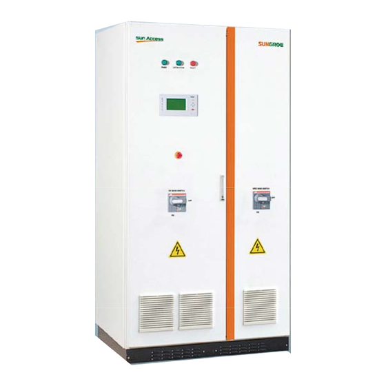
Page 23: Fig 3-2 External Appearance Of Sg100Ku
Introduction Fig 3-2 shows the locations of basic controlling and information display elements that help users perform control and monitoring tasks. Fig 3-2 External Appearance of SG100KU Component Name Comments LED Indicators Power, Operation and Fault LCD and Keys Display data and perform control functions... -
Page 24: Dimensions And Weight
Dimensions and Weight The SG100KU inverter’s dimensions are 40inchx75inchx31inch (1015mmx1907mmx785mm, W×H×D, including the devices on the front panel). The SG100KU inverter weighs approximately 1984 Ibs (900 kg). Please take this large dimensions and heavy weight into consideration during shipping, moving and installation. -
Page 25: The Bottom And Top Views
Cooling air is fed in via the base inlet and shutters on front and rear panels. The cooling air outlets are on the top of the SG100KU. Cooling fans’ power consumption is 240W and the outlet air flow is 60000ft /h (1620m /h), see Fig 3-5. -
Page 26: Electrical Connections Interface
SG100KU Installation Manual Electrical Connections Interface SG100KU provides multiple electrical terminals, see Fig 3-6. Fig 3-6 Electrical Connections Interfaces of SG100KU Name Comments RS485 Terminals DC- Input Terminals AC Output Terminals To 3-phase Grid through AC main breaker. Leave N Vacant in 3-phase-3-wire grid... -
Page 27: Data Acquisition
3.6.1 Grid Requirements The output of SG100KU is designed to fit the 480V 3-phase-4-wire grid system, which includes L1, L2, L3, Neutral and power ground. 480V 3-phase-3-wire grid is acceptable. In 3-phase-3-wire grid, neutral terminal of SG100KU can be left vacant. -
Page 28: Personnel Requirements
3.6.5 Communication Requirements The basic communication interface of SG100KU is a RS485 serial communication, which can be easily connected to a PC through a RS485/RS232 Converter. An Ethernet method and GPRS method can be extended optionally with specific... -
Page 29: Installation Design
Installation Design About This Chapter This chapter provides the PV plant system solution with optional devices from SUNGROW, information about how to design the installation environment, how to arrange installation procedure. Read this chapter to get information for installing the SG100KU. -
Page 30: The Solution With Optional Devices From Sungrow
SG100KU Installation Manual The Solution with Optional Devices from SUNGROW PV Grid-connected system configured with optional devices from SUNGROW is shown in Fig 4-1. Fig 4-1 The Solution from SUNGROW Name Comments SolarInfo EM Environment Applied to PV power generation system to measure the Monitoring Device wind speed, wind direction and solar radiation. -
Page 31: Basic Requirements
The foundation must guarantee solid and safe positioning of the inverter. It must provide the load-carrying capacity necessary to cope with the weight of the inverter. SG100KU is designed for indoor use only and must be placed to a level concrete floor or pad. -
Page 32: Clarence Space
Fig 4-2 Clearance Space around the SG100KU 4.3.3 Cable Trench The external cables of the SG100KU route into or out of the cabinet via the base. Cable trenches or steel supports above the floor are recommended (Refer to relevant design guides or standards). -
Page 33: Ventilation
Cable Support Arms 4.3.4 Ventilation The heat generated (exhaust hot air) by the SG100KU must be dissipated out of the electrical service room as soon and as much as possible, in order to guarantee safe operation and high feed-in power. -
Page 34: Wiring Specification
Installation Manual During operating the SG100KU will make some noise (≤80db), install the SG100KU in industrial environment and avoid the vicinity to living area or office area. After wiring, the cable entry and exit holes should be covered by the slid plates. And the rest gaps should be filled by urethane foam in order to keep mouse or other creatures from entering the cabinet. -
Page 35: Tightening Torques And Cable Protection
Strong electric current in power cables. Protect the insulating layer from sharp − edges. Tighten power cables up with insulated cable ties if necessary. − Installation Process Fig 4-4 shows the installation process of the SG100KU. And Table 4-3 gives a description about it. -
Page 36: Fig 4-4 Installation Process Of The Sg100Ku
AC grid connections Ground connection Communication connection Installation Check Check mechanical installation 8 Installation Checklist Check electrical connection Others Commissioning Check before commissioning 9 Commissioning Preparations before start-up Start-up procedure Complete the commissioning Fig 4-4 Installation Process of the SG100KU... -
Page 37: Preparations For Installation
Preparations for Installation About This Chapter This chapter illustrates preparations for installation of the SG100KU, including checking the unit and required tools. -
Page 38: Checking The Unit
Please contact Sungrow immediately in case you find any visual damage or lost of the delivery components supposed to be included in the package. Check that there are no signs of damages. Before installation and operation, check the information on the crate to verify that the delivery is of the correct type. -
Page 39: Mechanical Installation
Mechanical Installation About This Chapter This chapter describes the mechanical installation procedure of the SG100KU. -
Page 40: Transport And Shipping
Only the specific transport methods for SG100KU are acceptable. And note the heavy weight of the equipment and the non-central center of gravity. The SG100KU inverter weighs at least 1984 Ibs (900kg). Please take this heavy weight into consideration during shipping and moving. -
Page 41: Moving The Packed Sg100Ku
Mechanical Installation 6.1.2 Moving the Packed SG100KU Pay attention to the symbols and data on the crate, to make an informed choice on modes of transport and installation site, see Table 6-1. Table 6-1 Symbol and Data Name on Crate... -
Page 42: Fig 6-1 Moving The Packed Sg100Ku
SG100KU Installation Manual Forklift or crane can be employed to move the crate that contains the SG100KU. The recommended way to transport the SG100KU is using forklift, see Fig 6-1 A: Place the forks of the forklift to the bottom of wooden crate. -
Page 43: Fig 6-2 Using A Forklift To Move The Sg100Ku With The Wooden Pallet
Mechanical Installation Move the SG100KU after Unpacking Forklift, rail steels or crane can be employed to move the SG100KU after unpacking. If the unpacked SG100KU is far from the final position, the wooden pallet could be moved with the SG100KU, see Fig 6-2. -
Page 44: Fig 6-4 Using Rail Steels Or Crane To Move The Sg100Ku
Lubricant can be sprayed on the surface of the rail steels to make the movement easier. If the only available way to move the SG100KU is by crane, you can order the angle irons and relevant parts for lifting from SUNGROW for free; see Fig 6-4 B. -
Page 45: Field Installation
Remove the inverter’s anchor hardware that bolts the inverter to the pallet. Remove the front and rear base covers. − Unscrew the nuts under the wooden pallet. − Pull up the bolts. − Fig 6-5 Cross-section View of the SG100KU Fasten on the Wooden Pallet... -
Page 46: Place The Sg100Ku
Move the SG100KU into position. 6.2.3 Fastening the SG100KU to Floor SG100KU must be fastened to the floor as follows: Remove the front and rear base covers. Fasten the cabinet to the channel steels or floor using M12 bolts and nuts, see Fig 6-6. -
Page 47: Electrical Connection
Electrical Connection About This Chapter This chapter describes the step-by-step electrical connection process needed to complete the installation the SG100KU. -
Page 48: Cable Specifications
SG100KU Installation Manual Cable Specifications All wiring methods and processes should be in accordance with Local Electrical Code. The DC input cables (including DC positive and DC negative) must be chosen according to the recommended rating below. Table 7-1 DC Cables Recommended Sizes... -
Page 49: Parts For Cabling
Electrical Connection The communication cables must be chosen according to the recommended sizes below. Table 7-4 Communication Cables Recommended Sizes Cable Requirements (mm Requirements (AWG) Communication cable 0.75 Shield cables are recommended. Based on the above tables, users should use proper cables for different terminals with different specifications. -
Page 50: Start Electrical Connections
Installation Manual Start Electrical Connections 7.3.1 Open the Door The SG100KU is stopped and latched during shipping; users must open the front door of SG100KU for wiring. Switch off both the AC and DC main switches (turn both the switches counter-clockwise). -
Page 51: Open The Cable Entry/Exit Holes
Open the Cable Entry/Exit Holes The external cables are routed into or out of the cabinet via the cable entry/exit holes at the bottom the SG100KU. The corresponding sliding plates should be removed for wiring. Turn the screws in the back of the sliding plate counter-clockwise Slide the plates backwards, to open the holes. -
Page 52: Dc Connections
SG100KU Installation Manual DC Connections The DC input copper bus is located in the lower left corner of the inverter; there are 6 DC inputs in the DC copper bus with OT70 lugs. Cables rated for a minimum of 600V are required for connecting the inputs of the inverter. -
Page 53: Fig 7-5 Dc Input Cable Routing
Electrical Connection Fig 7-5 DC Input Cable Routing DC- grounding is required in contract. It connect DC- terminal to ground copper bus by leakage current sensor before leave factory. Therefore it is needed to firmly attach PE copper bar to grounding electrode. -
Page 54: Ac Grid Connections
To reduce the risk of fire, connect only to a circuit provided with 340A maximum branch circuits over current protection. When connect external AC cables to the SG100KU, positive phasing sequence must be maintained throughout the installation process. The connection terminals are located in the lower right corner of cabinet. Connection process as follows: Ensure that the AC grid cables with no electricity. -
Page 55: Ground Connections
It is crucial for safety to connect all inverters to ground via appropriately sized conductor. PE copper bar has been firmly connected to enclosure of inverter inside the SG100KU before delivery. Therefore it is needed to firmly attach PE copper bar to grounding electrode. - Page 56 SG100KU Installation Manual Fig 7-7 Ground Cable Routing This product can cause a DC current in the external protective earthing conductor. Where a residual current-operated protective (RCD) or monitoring (RCM) device is used for protection in case of direct or indirect contact,...
-
Page 57: Communication Connection (Optional)
Electrical Connection Communication Connection (Optional) SG100KU supplies RS485 interface to install communication between inverter and a PC or a data logger. And there is also a RS485/RS232 converter needed to connect SG100KU to PC Route the communication cables through the cable entry holes to the RS485 A/B terminals, see Fig 7-8. -
Page 58: Close The Cable Entry/Exit Holes
SG100KU Installation Manual RS485 cable should be shielded twisted-pair for good communication (RVVP-2*1.0 shielded twisted-pair cable is recommended). Shielding layer of RS485 cable should be single-point grounded in the site of monitor terminal. Close the Cable Entry/Exit Holes After all the electrical connections, cable entry/exit holes must be closed to protect interior against dirt, soiling and creatures (mouse or pest). -
Page 59: Installation Checklist
Installation Checklist About This Chapter This chapter describes the items needed to verify whether your installation of the SG100KU is correct. - Page 60 SG100KU Installation Manual Check the mechanical and electrical installation of the inverter before commissioning. Go through the checklist below with another person together. Mechanical Installation Check all the mechanical connections and make sure there is no damage, scratch or □...
-
Page 61: Commissioning
Commissioning About This Chapter This chapter describes how to start the SG100KU for the first time, including requirements of commissioning, Inspection before start-up, start-up procedures and completing the commissioning. -
Page 62: Requirements Of Commissioning
Requirements of Commissioning Before starting the device for the first time, all work performed on the device should be checked thoroughly. Check the voltages of AC and DC sides meet the requirements of SG100KU. Inspection before Start-up 9.2.1 PV Array Check Before start-up, check the PV array: Check open-circuit voltage of each PV string matches the nominal input voltage. -
Page 63: Serial Communication Check (Optional)
If all tests and measurements have been performed, and all measured values lie within the acceptable range, then the device can be switched on for the first time. Before start up the SG100KU, ensure that: Nobody is working on the inverter. -
Page 64: Complete The Commissioning
“RUN” LCD will both light, with the state of the LCD menu be changing to “Run”. After the SG100KU entering normal operation, set the time to local time via LCD control panel, refer to the Operation Manual. -
Page 65: Appendix
Appendix About This Chapter This chapter gives technical data of the SG100KU, exclusion of liability and the way to contact us. -
Page 66: Technical Data
SG100KU Installation Manual 10.1 Technical Data The following tables list the technical data of the SG100KU. Basic production information and performance of the SG100KU are available from these tables. 10.1.1 DC Parameters Parameter Specification Max. DC Voltage 600Vdc Start Voltage... -
Page 67: Mechanical Parameters
Appendix 10.1.3 Mechanical Parameters Parameter Specification Dimensions(W×H×D) 40inchx75inchx31inch (1015mmx1907mmx785mm) Weight 1984Ibs (900kg) 10.1.4 System Parameter Specification CEC Weight Efficiency 96.5% (with transformer) Max. Efficiency 97.2% (with transformer) Protection Degree IP20 (Indoor) (TYPE1) Power Consumption at Night <30W Operating Temperature -25°C ~ 55°C (-13~+13°F) Cooling Method Controlled force-air cooling Relative Humidity... -
Page 68: Exclusion Of Liability
In case of unforeseen calamity or force majeure. The use of supplied software produced by Sungrow Power Supply Co., Ltd.. is subject to the following conditions: Sungrow Power Supply Co., Ltd. rejects any liability for direct or indirect damages arising from the use of the SolarInfo software. -
Page 69: About Us
The power rating of Sungrow products covers from several hundred watt to large mega-watt systems. The pursuit of Sungrow is to help our customers acquire stable and clean power with minimum cost, maximum reliability and enhanced safety.
Need help?
Do you have a question about the SG100KU and is the answer not in the manual?
Questions and answers