
Related Manuals for Thermal Arc TA-8/300-KAT


Summary of Contents for Thermal Arc TA-8/300-KAT
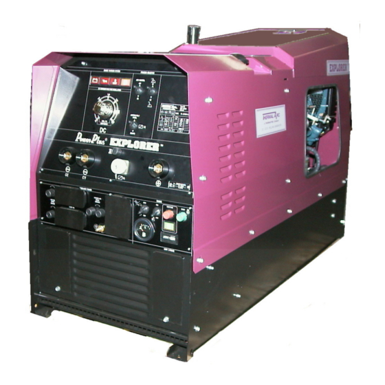
- Page 1 MODEL TA-8/300-KAT DC CC/CV Welding Generator STICK • • Auxiliary Power • INSTRUCTION MANUAL October 27 ,2003 Manual No. 430429-484 MI146-06-00-04...
- Page 2 ref. FT8300KAT.TIF...
- Page 3 Proposition 65 WARNING: This product, when used for welding or cutting, produces fumes or gases which contain chemicals known to the State of California to cause birth defects and, in some cases, cancer. (California Health & Safety Code Sec.25249.5 et seq.)
- Page 4 The publisher does not assume and hereby disclaims any liability to any part for any loss or damage caused by any error or omission in the Thermal Arc DC CC/CV Welding Generator Model TA-8/300-KAT Instruction Manual, whether such error results from negligence, accidental, or any other cause.
-
Page 5: Table Of Contents
TABLE OF CONTENTS 1. GENERAL INFORMATION.....................6 1.01 Notes, Cautions and Warnings .........................6 1.02 Important Safety Precautions ...........................6 1.03 Publications..............................8 1.04 Note, Attentions et Avertissement........................9 1.05 Precations De Securite Importantes .........................9 1.06 Publications..............................11 2. STATEMENT OF WARRANTY.....................13 3. TECHNICAL SPECIFICATIONS ..................15 4. -
Page 6: General Information
GENERAL INFORMATION GASES AND FUMES Gases and fumes produced during the Arc 1.01 Notes, Cautions and Warnings welding/cutting process can be dangerous and hazardous to your healt. Throughout this manual,notes,cautions,and • Keep all fumes and gases from the breathing warnings used highlight important... -
Page 7: Electric Shock
• Hydrogen gas may be formed and trapped under aluminium workpieces when they ELECTRIC SHOCK are cut underwater or while using a water table. DO NOT cut aluminium alloys Electric Shock can injure or kill. The arc welding process uses and produces high voltage electrical underwater or on a water table unless the energy. -
Page 8: Publications
Keep helmet and safety glasses in good condition. 7. AWS Standard A6.0, WELDING AND replace lenses when cracked, chipped or dirty. CUTTING CONTAINERS WICH HAVE • HELD COMBUSTIBLES, obtainable from Protect others in the work area from the arc American Welding Society, 550 N.W. Lejeune rays. -
Page 9: Note, Attentions Et Avertissement
Il faut communiquer aux opérateurs et au personnel TOUS les dangers possibles lisez, ANSI Standard Z88.2, PRACTICE FOR comprenez et suivez tous les avertissement, toutes RESPIRATORY PROTECTION, obtainable les précautions de sécurité et toutes les consignes from American National Standards Instiute, avant d’utilizer le materiel. - Page 10 • Soyez certain qu’aucune matière combustible • Utilisez un équipment spécial tel que des ou inflammable ne se trouve sur le lieu de tables de coupe à débit d’eau ou à courant travail. Protéges toute telle matière qu’il est descendant pour capter la fumée et les gaz. impossible de retirer de la zone de travail.
-
Page 11: Publications
4. Norme ANSI Z87.1, PARTIQUES SURES POUR LA PROTECTION DES YEUX ET DU VISAGE AU TRAVAIL ET DANS LES BRUIT ECOLES, disponible de l’ Institute Américain, des Normes Nationales (American National Le bruit peut provoquer une perte permanente de Standard Institute), 1430 Broadway, New l’ouie. - Page 12 12. Norme CSA W117.2, CODE DE SÉCURITÉ POUR LE SOUDAGE ET LA COUPE, disponible aupres de l’Association des Normes Canadiennes, Standards Sales, 178 Rexdale Boulevard, Rexdale, Ontario, Canada M9W 1R3. 13. Invret NWSA, BIBLIOGRAPHIE SUR LA SÉCURITÉ SOUDAGE, disponible auprès l’Association Nationale Fournitures de Soudage (National Welding...
-
Page 13: Statement Of Warranty
(hereinafter “Purchaser”) for service interruption. The remedies of the Purchaser set forth herein are exclusive and the liability of Thermal Arc with respect to any contract, or anything done in connection therewith such as the performance or breach thereof, or from the manufacture, sale, delivery, resale, or use of any goods covered by or furnished by Thermal Arc whether arising out of contract, negligence, strict tort, or under any warranty, or otherwise, shall not, except as expressly provided herein, exceed the price of the goods upon which such liability is based. - Page 14 Warranty repairs or replacement claims under this limited warranty must be submitted to Thermal Arc by an authorized Thermal Arcâ repair facility within thirty (30) days of the repair. No transportation costs of any kind will be paid under this warranty. Transportation charges to send products to an authorized warranty repair facility shall be the responsability of the customer.
-
Page 15: Technical Specifications
3. TECHNICAL SPECIFICATIONS WELDING GENERATOR DC DC amperage range 30÷300A of continuous control DC welding current 300A 60% duty cycle DC welding current 210A 100% duty cycle CC Mode / CV Mode VOLTAGE 70 OCV 15 to 30 Load Volt AUXILIARY POWER 60 Hz Single Phase 115 V 3,5 kVA - 230 V 8,5 kVA... -
Page 16: Front Panel Description
4. FRONT PANEL DESCRIPTION ref. T8300KAT.DWG ENGINE WARNING SYSTEM PROCESS SELECTOR ARC CONTROL DC CURRENT/VOLTAGE REGULATION HERMAL A THERMADYNE Company & AMPERE/VOLT PANEL VOLTS " AMPERES REMOTE EXPLORER 115V 3A CIRCUIT BREAKER " Amperage / Voltage control - The Amperage / Voltage control selects the desired Amperage or voltage (depending on mode) withing the entire range of the welding generator. - Page 17 Remote Control AMPERAGE / VOLTAGE Switch - This selector switch determines the adjustment of Amperage/Voltage. In the PANEL position, Amperage/Voltage is controlled by the front panel control knob. For remote Amperage/Voltage control, set the switch to REMOTE 14 for control through the 14 pin receptacle with a remote Amperage/Voltage device.
- Page 18 FRONT PANEL DESCRIPTION ref. T300KT1.DWG AUXILIARY POWER ENGINE AUTO GLOW PLUG START 115/230V 40A CIRCUIT BREAKER HIGH STOP 115V 20A CIRCUIT 115V AC BREAKER 230V AC 115V 20A Circuit Breakers - Push to reset. Controls 115V power source for the 115V duplex GFCI receptacles.
-
Page 19: Overall Dimensions Weight Base Mounting
5. OVERALL DIMENSIONS WEIGHT BASE MOUNTING OVERALL DIMENSION Dimensions Height 850 mm 33,46 in Width 530 mm 20,86 in Lenght 1330 mm 52,36 in 15 mm 0,59 in 1300 mm 51,18 in 34 mm 1,38 in 462 mm 18,18 in 10,5 mm Dia 0,41 in Errore. -
Page 20: Specifications
6. SPECIFICATIONS CAUTION CONTINUAL EXCEEDING OF DUTY DESCRIPTION CYCLE RATINGS can cause damage to the welding power source. The Thermal Arc TA-8/300-KAT is Diesel engine driven DC welding generator with • Do not exceed indicated duty cycles. selectable Constant Current (CC) Constant Voltage (CV) output characteristics. -
Page 21: Installing Welding Generator
7. INSTALLING WELDING GENERATOR 1. Lifting forks. 2. Lifting eye Use lifting eye or lifting forks to move unit. If using lifting forks, extend forks beyond opposite side of unit. 3. Trailer Install unit on trailer according to trailer manufacturing. Movement Do not lift unit from ref. -
Page 22: Warning
8. WARNING SPARKS CAN CAUSE BATTERY GASES TO EXPLODE BATTERY ACID CAN BURN EYES AND SKIN - Stop engine before disconnecting or connecting battery cables. - Always wear a faceshield and proper protective cloting when working on battery. - Do not allow tools to cause sparks when working on battery. 1. -
Page 23: Generator Auxiliary Power System
9. GENERATOR AUXILIARY POWER SYSTEM 9.01 SELECTING EQUIPMENT WARNING 1. Auxiliary power receptacles. - Neutral bonded to frame. 2. 3-Prong plug from case. Grounded equipment. 3. 2-Prong plug from double insulated equipment. Be sure equipment has this symbol and/or wording. Double insulation ref. -
Page 24: Wiring Optional 230 Volt Plug
10. WIRING OPTIONAL 230 VOLT PLUG The plug can be wired for a 230V, 2-wire load or a 115/230V, 3-wire load. White - Neutral terminal. YYY - Load 1 terminal. XXX - Load 2 terminal. Green - Ground terminal. ref. TA500D17.TIF... -
Page 25: Grounding The Generator To Atruck Or A Trailer Frame
11. GROUNDING THE GENERATOR TO A TRUCK OR A TRAILER FRAME 1. Generator base. 2. Metal vehicle frame. 3. Equipment grounding terminal. 4. Grounding cable. Use #10 AWG or larger insulated copper wire. ref. TA300K6.TIF Grounding methods Electrically bond generator to vehicle frame by metal-ti- metal contactor 12. -
Page 26: Selecting And Preparing Weld Output Cables
13. SELECTING AND PREPARING WELD OUTPUT CABLES 1. Weld output cable. Determine total cable lenght in weld circuit and maximum welding amperes. Use shortest cables possible. Do not use damaged cables. 2. Welding socket: Negative connection CC-WORK. 3. Welding socket: Positive connection CV-WORK. 4. -
Page 27: Typical Process Connections
14. TYPICAL PROCESS CONNECTIONS ref. T300KT2.DWG 15. POWER REQUIRED TO START MOTOR 1. Motor start code. AC MOTOR 2. Running amperage. VOLT AMPS 3. Motor HP. COMPRESSOR HZ 4. Motor voltage. PHASE Three-Phase induction motor starting requirments MOTOR START CODE VENTILATOR COMPRESSOR kVA/HP... -
Page 28: Selecting Weld Cables Sizes
16. SELECTING WELD CABLES SIZES Total Cable (Copper) Lenght in Weld circuit Not Exceeding 100 ft. (30 m) 150 ft. 200 ft. 250 ft. 300 ft. 350 ft. 400 ft. Welding (45 m) (60 m) (70 m) (90 m) (105 m) (120 m) or Less Amperes... -
Page 29: Weld Output Connection
17. WELD OUTPUT CONNECTION CONNECTOR INSTALLATION Install the supplied male connectors onto proper cables. 1. Obtain cable of desired lenght and proper size for installation. 2. If the installation requires cable large than 3/0 AWG, prepare one end of 3/0 AWG pigtail no longer than 2 ft (0,61 m) for connector installation. -
Page 30: Sequence Of Operation
18. SEQUENCE OF OPERATION WARNING : Read and follow all safety precaution before proceding with operation. 18.01 SHELDED METAL ARC WELDING (SMAW) 1. Install and connect unit according to the installation section. 2. Wear gloves and clothing. 3. Connect work clamp at workplace. 4. -
Page 31: Routine Maintenance
19. ROUTINE MAINTENANCE ATTENTION : STOP ENGINE BEFORE MAINTENANCE ref. FILTER.TIF ref. FLUIDSLE.TIF ref. WELDTERM.TIF ref. CHANGEOI.TIF ref. CHANGEOF.TIF... - Page 32 ref. CLEANCS.TIF ref. CLEANBC.TIF ref. CLEANSAC.TIF ref. REPLUL.TIF ref. REPLFF.TIF...
- Page 33 ref. CHECKVC.TIF ref. CHECKSA.TIF...
-
Page 34: Parts List
20. PARTS LIST 20.01 STATOR PARTS... - Page 35 Item N° Thermal Arc Denomination Ordering Number 11-3339 Shock absorber 11-4031 Ring 11-3964 Left engine support bracket 11-3965 Spacer 11-3963 Right engine support bracket 11-3972 Fuel filter support 11-4178 Throttle plate support 11-3325 Pin 11-3326 Throttle spring 11-3322 Bush 11-3384 Washer...
-
Page 36: Front Panel And Instrument Parts
20.02 FRONT PANEL AND INSTRUMENT PARTS... - Page 37 Item N° Thermal Arc Denomination Ordering Number 11-3049 Rubber black cup 11-3048 Washer 11-3148 20 A circuit breaker 11-3984 Front plate 11-3985 Lower alluminium front plate 11-3232 Plug for outlet welding 11-3231 Outlet welding 11-3119 8 A fuse 11-3118 Fuse holder...
-
Page 38: Sheet Parts
20.03 SHEET PARTS... - Page 39 Item N° Thermal Arc Denomination Ordering Number 11-3979 Battery cover 11-3192 Negative battery charging clip 11-3188 Battery plate 11-3193 Cover negative clip 11-3191 Cover positive clip 11-3190 Positive battery charging clip 11-3499 Flap 11-3990 Canopy 11-3971 Suction rubber tube 11-3974 Air filter rubber tube...
- Page 40 Item N° Thermal Arc Denomination Ordering Number 11-3983 Fuel tank 11-3992 Silencer 11-3947 Battery clamp 11-3543 44 Ah 12 V battery 11-3962 Battery tierod...
-
Page 41: Wiring Diagram
21. WIRING DIAGRAM HERMAL A THERMADYNE Company...
Need help?
Do you have a question about the TA-8/300-KAT and is the answer not in the manual?
Questions and answers