
Related Manuals for Thermal Arc LM-200 ARCMASTER


Summary of Contents for Thermal Arc LM-200 ARCMASTER
-
Page 1: Service Manual
LM-200 ARCMASTER INVERTER ARC WELDER Service Manual Version No: 1 Issue Date: May 22, 2006 Manual No.: 0-4943B Operating Features: PHASE S M AW... - Page 2 800-752-7621, or visit us on the web at www.thermalarc.com. This Operating Manual has been designed to instruct you on the correct use and operation of your Thermal Arc ® product. Your satisfaction with this product and its safe operation is our ultimate concern. Therefore, please take the time to read the entire manual, especially the Safety Precautions.
- Page 3 While the information contained in this Manual represents the Manufacturer’s best judgment, the Manufacturer assumes no liability for its use. Service Manual Number 0-4943B for: ArcMaster LM-200 Inverter Welding Power Supply Part No. 10-3092 Published by: Thermadyne Industries, Inc. 82 Benning Street...
-
Page 4: Table Of Contents
3 Weld Process selection for the LM-200 ........ - Page 5 7 VOLTAGE REDUCTION DEVICE (VRD) 1 VRD Specification ................7–1 2 VRD Maintenance .
- Page 6 CONTENTS 2.4. 20 Switch (S1) ................9–37 2.4.
-
Page 7: Safety Instructions And Warnings
ARCMASTER LM 200 SECTION 1: SAFETY INSTRUCTIONS AND WARNINGS WARNING PROTECT YOURSELF AND OTHERS FROM POSSIBLE SERIOUS INJURY OR DEATH. KEEP CHILDREN AWAY. PACEMAKER WEARERS KEEP AWAY UNTIL CONSULTING YOUR DOCTOR. DO NOT LOSE THESE INSTRUCTIONS. READ OPERATING/INSTRUCTION MANUAL BEFORE INSTALLING, OPERATING OR SERVICING THIS EQUIPMENT. - Page 8 ARCMASTER LM 200 3. Use protective screens or barriers to protect others from flash and glare; warn others not to watch the arc. WARNING 4. Wear protective clothing made from durable, flame-resistant material (wool and leather) and foot protection. WELDING can cause fire or explosion. 5.
- Page 9 ARCMASTER LM 200 2. If used in a closed area, vent engine exhaust outside and away from any building air intakes. WARNING WARNING FLYING SPARKS AND HOT METAL can cause injury. Chipping and grinding cause flying metal. As welds cool, they can throw off slag.
-
Page 10: Principal Safety Standards
ARCMASTER LM 200 1.02 Principal Safety Standards Safety in Welding and Cutting, ANSI Standard Z49.1, from American WARNING Welding Society, 550 N.W. LeJeune Rd., Miami, FL 33126. Safety and Health Standards, OSHA 29 CFR 1910, from Superintendent STEAM AND PRESSURIZED HOT COOLANT can burn of Documents, U.S. - Page 11 ARCMASTER LM 200 1.03 Precautions de Securite en Soudage à l’Arc MISE EN GARDE LE SOUDAGE A L’ARC EST DANGEREUX PROTEGEZ-VOUS, AINSI QUE LES AUTRES, CONTRE LES BLESSURES GRAVES POSSIBLES OU LA MORT. NE LAISSEZ PAS LES ENFANTS S’APPROCHER, NI LES PORTEURS DE STIMULATEUR CARDIAQUE (A MOINS QU’ILS N’AIENT CONSULTE UN MEDECIN). CONSERVEZ CES INSTRUCTIONS.
- Page 12 ARCMASTER LM 200 AVERTISSEMENT AVERTISSEMENT LES VAPEURS ET LES FUMEES SONT DANGEREUSES LE RAYONNEMENT DE L’ARC PEUT BRÛLER LES YEUX POUR LA SANTE. ET LA PEAU; LE BRUIT PEUT ENDOMMAGER L’OUIE. Le soudage dégage des vapeurs et des fumées L’arc de soudage produit une chaleur et des rayons dangereuses à...
- Page 13 ARCMASTER LM 200 7. Ne soudez des tôles galvanisées ou plaquées au plomb ou au cadmium que si les zones à souder ont été grattées à fond, que si AVERTISSEMENT l’espace est bien ventilé; si nécessaire portez un respirateur à ad- duction d’air.
-
Page 14: Principales Normes De Securite
ARCMASTER LM 200 Les accumulateurs contiennent de l’électrolyte acide et 1. Utilisez l’équipement à l’extérieur dans des aires ouvertes et bien ventilées. dégagent des vapeurs explosives. 2. Si vous utilisez ces équipements dans un endroit confiné, les 1. Portez toujours un écran facial en travaillant sur un accumu-lateur. fumées d’échappement doivent être envoyées à... -
Page 15: Symbol Legend
SYMBOL LEGEND STICK Amperage (Shielded Metal Arc SMAW) Pulse Current Function Voltage Spot Time (GTAW) Hertz (frequency) Remote Control Seconds (Panel/Remote) Remote Function Percent Arc Control (SMAW) DC (Direct Current) Gas Post-Flow AC (Alternating Current) Gas Pre-Flow Standard Function Voltage Reduction Device Slope Function Circuit Negative... -
Page 16: Introduction And Description
Description INTRODUCTION AND DESCRIPTION The Thermal Arc™ LM-200 is a single & three-phase DC arc welding power source with Constant Current (CC) and Constant Voltage (CV) output characteristics. This unit is equipped with a Digital Volt/Amperage, lift arc starter for use with Gas Tungsten Arc Welding (GTAW), Arc Control and Hot Start for Shielded Metal Arc Welding (SMAW), Inductance Control for Gas Metal Arc Welding (GMAW) processes. -
Page 17: Transporting Methods
ELECTRIC SHOCK can kill; SIGNIFICANT DC VOLTAGE is present after removal of input power. 4.1 Environment DO NOT TOUCH live electrical parts. The LM-200 is designed for use in hazardous envi- ronments. SHUT DOWN welding power source, disconnect input power employing lockout/tagging procedures. -
Page 18: Input Power
LM-200 INTRODUCTION AND DESCRIPTION 5.2 Input Power NOTE These units are equipped with a three-conductor Each unit incorporates an INRUSH circuit and input with earth power cable that is connected at the voltage sensing circuit. When the MAIN SWITCH is... -
Page 19: Specifications
Phase 208V 230V 460V Thermal Arc continuously strives to produce the best product possible and therefore reserves the right to change, improve or revise the specifica- tions or design of this or any product without prior notice. Such updates or changes do not entitle the... -
Page 20: Operator Controls
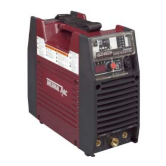
CAUTION Figure 3-1: LM-200 Power Source Loose welding terminal connections can cause overheating and result in the male plug being fused in the bayonet terminal and /or melting of the hous- ing (case). -
Page 21: Weld4 Parameter Descriptions For Lm-200
500V potential with respect to earth. 7. Input Cable Figure 3-2: LM-200 Front Panel with Parameter Description The input cable connects the Primary supply voltage to the equipment. 8. Voltage Input Select Switch (Smart Logic Switch) User selectable switch. -
Page 22: Weld Process Selection For The Lm-200
When this parameter is set to SAUVEGARDER CHARGER memory. 100%, ie maximum inductance, the arc has a slow Table 3-1: Weld Parameter Descriptions for LM-200 response with a resulting soft arc and fine spatter. NOTE As the INDUCTANCE is increased, the WELD (V) may need to be adjusted to achieve the desired weld characteristic. -
Page 23: Hot Start
LM-200 OPERATOR CONTROLS 4.3 HOT START i) Root runs During root runs the weld pool forms a "keyhole" This parameter operates in STICK mode and shape. If too much weld current is used, the improves the start characteristics for stick elec- hole blows out and the weld collapses. -
Page 24: Weld Parameters
0 to 100% CONTROL Save/Load A total number of 5 programs can function be saved into the LM-200 memory Table 3-4: Weld Parameters SAVE the Current Weld Parameters into Memory 4.7 Power Source Features Press the SAVE button ... - Page 25 LM-200 OPERATOR CONTROLS PAGE LEFT INTENTIONALLY BLANK 3 – 6...
-
Page 26: Sequence Of Operation
Set HOT START . Set ARC CONTROL. Set WELD current . Commence welding. Figure 4-1: LM-200 Front Panel LIFT TIG Welding 1. Contactor function - Pressing this buttons enables Contactor functions. Connect work lead to positive terminal. -
Page 27: Routine Maintenance
ROUTINE MAINTENANCE ROUTINE MAINTENANCE The only routine maintenance required for the power supply is a thorough cleaning and inspec- tion, with the frequency depending on the usage and the operating environment. WARNING Disconnect primary power at the source before opening the enclosure. Wait at least two minutes before opening the enclosure to allow the primary capacitors to discharge. -
Page 28: Basic Trouble Shooting
Do not attempt to open or repair unless you are an 5. Welding dirty, oily, painted, oxidized or greasy plate. Accredited Thermal Arc Service Agent and you ... Clean contaminates off the plate. have had training in power measurements and 6. -
Page 29: Mig Welding Problems
LM-200 BASIC TROUBLE SHOOTING 5. Liner blocked with wire debris. When using soft electrode wire such as alu- minium it may become jammed in the con- ... Wire debris is produced by the wire passing tact tip due to expansion of the wire when through the feed roller, if excessive pressure heated. -
Page 30: Tig Welding Problems
D Decrease voltage by reducing the WELD (V) control. E Slow the cooling rate by preheating part to be welded or cool slowly. A Have an Accredited Thermal Arc Service 7 Cold weld puddle. A Faulty rectifier unit. Agent to test then replace the faulty B Loose welding cable connection. - Page 31 LM-200 BASIC TROUBLE SHOOTING Description Possible Cause Remedy 7 Dirty weld pool. A Electrode contaminated through contact A Clean the electrode by grinding off the with work piece or filler rod material. contaminates. B Gas contaminated with air. B Check gas lines for cuts and loose fitting or change gas cylinder.
-
Page 32: Stick Welding Problems
LM-200 BASIC TROUBLE SHOOTING Stick Welding Problems Description Possible Cause Remedy 1 Gas pockets or voids in A Electrodes are damp. A Dry electrodes before use. weld metal (Porosity). B Welding current is too high. B Reduce welding current. C Surface impurities such as oil, grease, C Clean joint before welding. - Page 33 LM-200 BASIC TROUBLE SHOOTING Example of lack of fusion Description Possible Cause Remedy 5 Non-metallic particles A Non-metallic particles may be trapped in A If bad undercut is present, clean slag out are trapped in the weld undercut from previous run.
-
Page 34: Power Source Problems
A Switch ON the Primary supply voltage. be established. switched ON. B Switch ON the Welding Power Source. B The Welding Power Source switch is C Have an Accredited Thermal Arc Service switched OFF. Agent repair the connection. C Loose connections internally. Defective control circuit. - Page 35 LM-200 BASIC TROUBLE SHOOTING PAGE LEFT INTENTIONALLY BLANK 6 – 8...
-
Page 36: Voltage Reduction Device (Vrd)
PCB. Plugging the an accredited Thermal Arc service agent. control PCB back into the front panel controls can only be achieved by removing the side covers. - Page 37 LM-200 Voltage Reduction Device (VRD) d. Turning the VRD ON/OFF (see Figure 7-3). To turn VRD ON: rote the trim potentiometer (VR1) on the display PCB fully clockwise. When VRD is turned ON check that it operates as per VRD Specifications on page 5-13.
-
Page 38: Power Source Error Codes
E01 resets when TH1 B Fan ceases to operate. B Have an Accredited about 1 second. decreases to 70°C for about Thermal Arc Service C Air flow is restricted by 30 seconds. Agent investigate. vents being blocked. C Unblock vents then let Power Source cool down. - Page 39 Buzzer sounds constantly. B Have an Accredited voltage has been turned off. Must switch machine off then Thermal Arc Service off but control circuit has on to reset E99 error. B Mains supply (input) Agent or a qualified power from the primary...
-
Page 40: Advanced Troubleshooting
The power supply, and replace those subsystems that faulty subassembly should then be returned to prove faulty. Thermal Arc through established procedures. CAUTION WARNING Troubleshooting and repairing this unit is a pro-... - Page 41 LM-200 ADVANCED TROUBLESHOOTING CAUTION The capacitors inside the power supply will slowly discharged after you turn off the switch of the power sup- ply or the switch at the breaker box (distribution panel). Wait at least 5 minutes for the discharge to complete.
- Page 42 LM-200 ADVANCED TROUBLESHOOTING 4) Pull the front panel slightly forward and pull the rear panel slightly backward. The interlocking hooks of the side case covers can now be disengaged from the front and rear panels. 5) Remove the side covers.
-
Page 43: Verification And Remedy To The Indicated Error Codes
LM-200 ADVANCED TROUBLESHOOTING 1.2 Verification and Remedy to 1.2.1 E01 "Over-Temperature at the primary side" the Indicated Error Codes Cause NOTE The capacitors inside the power supply will slowly Occurs when an over-temperature condition of the discharged after you turn off the switch of the primary IGBT is detected. -
Page 44: E02 "Over-Temperature At The Secondary Side
LM-200 ADVANCED TROUBLESHOOTING 1.2.2 E02 "Over-Temperature at the 1.2.3 E03 "Primary Over-Current Failure" secondary side" Cause Cause Occurs when excessive current is detected flow- ing into the primary side of the main transformer. Occurs when an over-temperature condition of the secondary IGBT and diode are detected. -
Page 45: E12 "Low Input Voltage Failure
LM-200 ADVANCED TROUBLESHOOTING Contact the manufacturer if you find any bro- 1.2.5 E12 "Low Input Voltage Failure" ken connectors or damaged wiring har- Cause nesses. c) Verify PCB4 (WK-4819) for burned or discol- Occurs when the input voltage is less than ored components or printed circuit board. -
Page 46: E85 "Pre-Charge Error
LM-200 ADVANCED TROUBLESHOOTING Confirm a secure connection of the harness between CN1 on PCB21 and CN2 on PCB3. wired between CN8 and CN9 on PCB6 and Contact the manufacturer if you find any bro- TH1 and TH2 and re-install the harnesses ken connectors or damaged wiring har- with a secure connection. -
Page 47: Verification And Remedy To Failures Without Indication Codes
LM-200 ADVANCED TROUBLESHOOTING 1.3 Verification and Remedy to 1.3.2 "Wire feeding failure or inconsis- tent wire delivery" (Wire feeder Failures without Indication does not work) Codes Refer to Note 11 on Page 9-4. Cause Refer to Note 12 on Page 9-4. -
Page 48: No Weld Output
LM-200 ADVANCED TROUBLESHOOTING When there is no voltage between "E" pin 1.3.3 "No weld output" and "F" pin in AC115V (AC100~125V), the connection of the pin of the connector is done Cause over again. Occurs when the 14-pin receptacle (19-pin recep- ... -
Page 49: "Operating Panel Failure" (Led's Do Not Light Properly Or Weld Settings Cannot Be Establish.)
LM-200 ADVANCED TROUBLESHOOTING Confirm the connections of the required Confirm a secure connection of the harness and the connections between CN21 on PCB6 cables; control cable for the wire feeder equipment, cable for welding, and a cable for and CN2 on PCB12. -
Page 50: Verification Of The Power Input Circuitry
LM-200 ADVANCED TROUBLESHOOTING 1.4.2 Verification of the Power Input the points V2 and W2 on the input switch, S1. Circuitry The location of points U2, V2 and W2 on switch S1are indicated in Figure 7-1. When Refer to Note 9 on page 9-2. -
Page 51: Power Supply Voltage Test
LM-200 ADVANCED TROUBLESHOOTING calculated measurement is not within the cor- PCB3 are indicated in Figure 9-5. responding range (260~360/580~720VDC) fol- lowing the process in section 9.2.4.23. TB1(P) PCB6 TB4(N) PCB2 Figure 9-4: The check points TP0-3 Figure 9-3: The check points TB1(P) and TB2(N) -
Page 52: Verification Of The Cooling Fan, Fan1, Drive Circuitry
LM-200 ADVANCED TROUBLESHOOTING 1.4.4 Verification of the Cooling Fan, Voltage FAN1, Drive Circuitry measurement Remedy Status (PIN1-PIN2 of Verify the condition of the cooling fan, FAN1, using CN11onPCB3) a DC voltmeter. (The capability of the voltmeter Replace PCB3 (WK-5548). should be more than 50VDC.) (Refer to section 9.2.4.4) -
Page 53: Verification Of The Secondary Diode (D2-7)
LM-200 ADVANCED TROUBLESHOOTING 1. Verify the characteristic of the secondary diode, D2, D3, D4, D5, D6 and D7 using a diode tester. 2. Refer bellow Table 9-2 and Figure 9-9 for the checkpoints on D2, D3, D4, D5, D6 and D7. -
Page 54: Verification Of No-Load Voltage (No Ocv)
LM-200 ADVANCED TROUBLESHOOTING CAUTION TERMINALS COMPONENT ACCEPTABL Electric shock hazard. The unit will generate OCV Positive Negative TESTED E VALUE immediately when contactor function is put into the lead lead state of on pushing Function button at STICK Collector-Emitter Open mode. -
Page 55: Output Load Test
LM-200 ADVANCED TROUBLESHOOTING 1.4.9 Output Load Test NOTE This completes the output load test. If the results of This test verifies that the output current, (amper- any step differ from those above, then refer to the age) controls are functioning properly. A clamp-... -
Page 56: Subsystem Test And Replacement Procedures
LM-200 ADVANCED TROUBLESHOOTING Subsystem Test and Replacement Procedures 2.1 Preparation This section provides specific procedures for verifying the operation and replacement of each subsystem within the power supply. Before undertaking any of these procedures, eliminate the obvious first-visually inspect the suspect sub- system for physical damage, overheating, and loose connections. - Page 57 LM-200 ADVANCED TROUBLESHOOTING DWG No. Parts name Reference page Note 9-22 PCB1 Print Circuit Board (WK-5493) 9-27 PCB6 Print Circuit Board (WK-5688) 9-27 PCB8 (Q1-Q6) Print Circuit Board (WK-5479) 9-27 PCB9 (Q7-Q12) Print Circuit Board (WK-5479) 9-28 PCB10 (Q13-Q18) Print Circuit Board (WK-5479)
- Page 58 LM-200 ADVANCED TROUBLESHOOTING DWG No. Parts name Reference page Note 9-46 CON1 14-PIN Receptacle 9-47 CON2 19-PIN Receptacle 9-39 Diode 9-40 Diode 9-40 Diode 9-40 Diode 9-40 Diode 9-42 MCB1 Molded Case Circuit Breaker 9-42 MCB2 Molded Case Circuit Breaker...
- Page 59 LM-200 ADVANCED TROUBLESHOOTING DWG No. Parts name Reference page Note 9-41 Current Trans 9-41 Current Trans 9-36 FAN1 Cooling Fan 9-34 FCH1 Inductor 9-39 HCT1 Current Sensor 9-41 Reactor 9-43 Resistor 9-43 Resistor 9-35 Thermistor 10 TH2 9-36 Thermistor 9 – 20...
-
Page 60: Service Tools
LM-200 ADVANCED TROUBLESHOOTING 2.3 Service Tools 2.3.1 Tools and parts The tools and parts to be used for maintenance are shown by icons. Long Nose Philips Head Silicon Spanner C-Ring Pliers Snap Band Pliers Compound Screwdriver (5.5, 8, 10, 17mm) 2.3.2 Notes of disassembly and assembly... -
Page 61: Replacement Procedure
LM-200 ADVANCED TROUBLESHOOTING 2.4 Replacement Procedure 2.4.1 PCB1 (WK-5493) 1) Remove the side cover. [Reference page: 9-1] 2) Remove PCB2 (WK-5597). [Reference page: 9-23] 3) Remove the diode (D1). [Reference page: 9-39] 4) Remove the current transformers (CT2 and CT3). [Reference page: 9-41] 5) Remove two screws and three terminals from PCB1 (WK-5493). -
Page 62: Pcb2 (Wk-5597)
LM-200 ADVANCED TROUBLESHOOTING 2.4.2 PCB2 (WK-5597) 1) Remove the side cover. [Reference page: 9-1] 2) Remove PCB6 (WK-5688). [Reference page: 9-27] 3) Remove one screw and three ground terminals. Disconnect 13 connectors. CN22 CN10 CN23 CN11 CN21 CN11 CN20 4) Loosen two screws. -
Page 63: Pcb3 (Wk-5548), Pcb7 (Wk-5689)
LM-200 ADVANCED TROUBLESHOOTING 6) Remove five screws, three terminals, and five connectors from PCB2 (WK-5597). 7) Cut off one snap band. Remove two board supports and then remove PCB2 (WK-5597) and the insulat- ing sheet. 2.4.3 PCB3 (WK-5548), PCB7 (WK-5689) 1) Remove the side cover. - Page 64 LM-200 ADVANCED TROUBLESHOOTING 6) Loosen two screws. Rotate the resistors (R2 and R3) to expose two screws on PCB3 (WK-5548). 7) Remove one screw and three ground terminals. Remove four screws and remove PCB3 and PCB7. Dis- connect five connectors from PCB7 (WK-5689).
-
Page 65: Pcb4 (Wk-4819)
LM-200 ADVANCED TROUBLESHOOTING 9) Disconnect two connectors from PCB3 (WK-5548). CN18 CN33 2.4.4 PCB4 (WK-4819) 1) Remove the side cover. [Reference page: 9-1] 2) Disconnect three connectors. Remove two screws and disconnect three connectors, and then remove PCB4 (WK-4819). -
Page 66: Pcb6 (Wk-5688)
LM-200 ADVANCED TROUBLESHOOTING 2.4.6 PCB6 (WK-5688) 1) Remove the side cover. [Reference page: 9-1] 2) Disconnect five connectors. CN21 CN20 3) Remove three screws and disconnect six connectors, and then remove PCB6 (WK-5688). CN27 CN18 CN30 CN31 CN32 ... -
Page 67: Pcb10 (Wk-5479), Pcb11 (Wk-5479)
LM-200 ADVANCED TROUBLESHOOTING 2.4.8 PCB10 (WK-5479), PCB11 (WK-5479) 1) Remove the side cover. [Reference page: 9-1] 2) Remove eight screws and four component clips. Disconnect four connectors and remove six screws, and then remove PCB10 (WK-5479) and PCB11 (WK-5479). -
Page 68: Pcb13 (Wk-5528)
LM-200 ADVANCED TROUBLESHOOTING 2.4.10 PCB13 (WK-5528) 1) Remove the side cover. [Reference page: 9-1] 2) Remove the operation cover. 3) Remove the jog dial cap. Loosen the screw while pressing the jog dial and then remove the jog dial. -
Page 69: Pcb14 (Wk-5594)
LM-200 ADVANCED TROUBLESHOOTING 5) Disconnect one connector and remove two screws, and then remove PCB13 (WK-5528). 2.4.11 PCB14 (WK-5594) 1) Remove the side cover. [Reference page: 9-1] 2) Remove PCB17 (WK-5699). [Reference page: 9-33] 3) Remove the inductor (FCH1). [Reference page: 9-34] 4) Remove two screws from the front side and detach the bus bar. -
Page 70: Pcb15 (Wk-5606)
LM-200 ADVANCED TROUBLESHOOTING 6) Remove two screws from PCB1 (WK-5477) and disconnect three terminals. Cut off two snap bands and slide the insulating tube. Remove two screws, two nuts, and four terminals. 7) Remove four screws from the bottom and disconnect one terminal. Remove two screws from the rear side and remove PCB14 (WK-5594) by pulling it out. -
Page 71: Pcb16 (Wk-4917)
LM-200 ADVANCED TROUBLESHOOTING 2.4.13 PCB16 (WK-4917) 1) Remove the side cover. [Reference page: 9-1] 2) Remove six screws from the switch (S1) and disconnect six terminals. 3) Remove four screws and open the rear board. 4) Disconnect the one connector. Remove the two screws and one ground terminal. Remove the PCB16 (WK-4917). -
Page 72: Pcb17 (Wk-5699)
LM-200 ADVANCED TROUBLESHOOTING 5) Remove the three screws and the bus bar from the PCB16 (WK-4917). 2.4.14 PCB17 (WK-5699) 1) Remove the side cover. [Reference page: 9-1] 2) Disconnect 11 connectors and remove one terminal. Remove four screws and remove PCB17 (WK- 5699). -
Page 73: Inductor (Fch1)
LM-200 ADVANCED TROUBLESHOOTING 4) Disconnect two connectors. Remove four board supports and remove PCB18 (WK-5499). 2.4.16 Inductor (FCH1) 1) Remove the side cover. [Reference page: 9-1] 2) Disconnect one connector. Remove one screw and three ground terminals. CN21 3) Remove two bolts and three terminals. Remove four screws and open the front cabinet. -
Page 74: Thermistor (Th1)
LM-200 ADVANCED TROUBLESHOOTING 4) Remove one screw, one terminal and one nut. 5) Remove four screws and remove the inductor (FCH1). 2.4.17 Thermistor (TH1) 1) Remove the side cover. [Reference page: 9-1] 2) Cut off one snap band and disconnect one connector. Remove one screw and remove the thermistor (TH1). -
Page 75: Thermistor (Th2)
LM-200 ADVANCED TROUBLESHOOTING 2.4.18 Thermistor (TH2) 1) Remove the side cover. [Reference page: 9-1] 2) Remove PCB17 (WK-5699). 3) Cut off three snap bands and disconnect one connector. Remove one screw and remove the thermistor (TH2). When replacing the thermistor with a new one, apply an oil compound (SHINETSU SILICONE G-747 or equivalent) evenly to the base. -
Page 76: Switch (S1)
LM-200 ADVANCED TROUBLESHOOTING 4) Remove two screws and remove the cooling fan (FAN1). Pay attention to the installation direction of the fan. 2.4.20 Switch (S1) 1) Remove the side cover. [Reference page: 9-1] 2) Remove six screws and six terminals. -
Page 77: Switch (S2 And S3)
LM-200 ADVANCED TROUBLESHOOTING 2.4.21 Switch (S2 and S3) 1) Remove the side cover. [Reference page: 9-1] 2) Remove six screws and six terminals. 3) Remove four screws and open the rear panel. 4) Cut off one snap band and disconnect one connector from PCB4 (WK-4819). Remove two screws and two nuts and remove the switch (S2). -
Page 78: Current Sensor (Hct1)
LM-200 ADVANCED TROUBLESHOOTING 2.4.22 Current Sensor (HCT1) 1) Remove the side cover. [Reference page: 9-1] 2) Remove PCB17 (WK-5699). [Reference page: 9-33] 3) Remove one screw and one terminal. Remove one bolt and one terminal. Disconnect one connector. Remove one screw and one nut and detach the bus bar. -
Page 79: Diode (D2, D4, D5, And D7)
LM-200 ADVANCED TROUBLESHOOTING 2.4.24 Diode (D2, D4, D5, and D7) 1) Remove the side cover. [Reference page: 9-1] 2) Remove PCB17 (WK-5699). [Reference page: 9-33] 3) Remove PCB15 (WK-5606). [Reference page: 9-31] 4) Remove one screw and one nut. Remove 20 screws and one terminal and detach the bus bar. -
Page 80: Current Transformer (Ct2 And Ct3)
LM-200 ADVANCED TROUBLESHOOTING 2.4.25 Current Transformer (CT2 and CT3) 1) Remove the side cover. [Reference page: 9-1] 2) Remove PCB6 (WK-5688). [Reference page: 9-27] 3) Remove four screws and open the rear cabinet. 4) Cut off one snap band and disconnect one connector from PCB3 (WK-5548). Remove two screws and two terminals from PCB1 (WK-5493). -
Page 81: Molded Case Circuit Breaker (Mcb1 And Mcb2)
LM-200 ADVANCED TROUBLESHOOTING 3) Remove two screws and two terminals. Cut off one snap band and remove the reactor (L1). 2.4.27 Molded Case Circuit Breaker (MCB1 and MCB2) 1) Remove the side cover. [Reference page: 9-1] 2) Remove six screws and six terminals. -
Page 82: Resistor (R2 And R3)
LM-200 ADVANCED TROUBLESHOOTING 4) Remove four terminals. Remove two nuts and remove the molded case circuit breakers (MCB1 and MCB2). purple Blue orange brown 2.4.28 Resistor (R2 and R3) 1) Remove the side cover. [Reference page: 9-1] 2) Remove the switch (S1). [Reference page: 9-37] 3) Remove four screws and four terminals. -
Page 83: Transformer (T1)
LM-200 ADVANCED TROUBLESHOOTING 2.4.29 Transformer (T1) 1) Remove the side cover. [Reference page: 9-1] 2) Cut off one snap band and disconnect one connector. Remove one screw and three ground terminals. Cut off two snap bands. 3) Cut the tap wires on the primary side of the transformer (T1), which are connected with the insulated ter- minal. - Page 84 LM-200 ADVANCED TROUBLESHOOTING 5) Cut off three snap bands. When reinstalling the transformer, secure the harnesses to the holders using snap bands. 6) Cut off one snap band. Cut off one snap band that ties together the harness of CN7 on PCB17 (WK- 5699) and the harness wired to the rear side.
-
Page 85: 14-Pin Receptacle (Con1)
LM-200 ADVANCED TROUBLESHOOTING 8) Remove four screws and remove the transformer (T1). 2.4.30 14-Pin Receptacle (CON1) 1) Remove the side cover. [Reference page: 9-1] 2) Disconnect three connectors. Remove one screw and three ground terminals. Cut off two snap bands. -
Page 86: 19-Pin Receptacle (Con2)
LM-200 ADVANCED TROUBLESHOOTING 4) Cut off five snap bands. When reinstalling the receptacle, bend both the harnesses of CN6/CN7/CN9/CN10 on PCB17 (WK- 5699) and the ones of N-pin/L-pin of 19-pin receptacle (CON2), and then use snap bands to tie together the bent harnesses and the ones of CN1/CN5/CN8 on PCB17 (WK-5699). - Page 87 LM-200 ADVANCED TROUBLESHOOTING 3) Cut off three snap bands. When reinstalling the receptacle, secure the harnesses to the holders using snap bands. 4) Cut off one snap band. Cut off one snap band that ties together the harness of CN7 on PCB17 (WK- 5699) and the harness wired to the rear side.
- Page 88 LM-200 ADVANCED TROUBLESHOOTING 6) Disconnect three connectors. Remove one screw and three ground terminals. Cut off two snap bands. 7) Cut the harnesses of N-pin/L-pin of the 19-pin receptacle (CON2), which are connected with the insu- lated terminals. 8) Remove two screws. Remove the cap and remove the 19-pin receptacle (CON2).
- Page 89 LM-200 ADVANCED TROUBLESHOOTING PAGE LEFT INTENTIONALLY BLANK 9 – 50...
-
Page 90: Appendix 1 Spare Parts List
To determine the part number, description, quantity, or application of an item, simply locate the item in question from the illustration and refer to that item number in the correspond- ing Parts List. SPEC NUMBERS: LM-200 ******-*** DWG No. Description Type & Rating QTY. - Page 91 LM-200 PARTS LIST DWG No. Description Type & Rating QTY. Code No. Order No. 29 S2 Switch SDKGA4-A-1-A 24704531400 10-6699 30 S3 Switch SDKGA4-A-1-A 24704531400 10-6699 31 T1 Tranceformer F3A216701 F3A216701 32 TH1, 2 Thermistor ERTA53D203 20kΩ/25°C B=3950K 46965000900 Front Panel...
- Page 92 LM-200 PARTS LIST DWG No. Description Type & Rating QTY. Code No. Order No. PCB1 Insulated Sheet E1B859700 E1B859700 PCB2 Insulated Sheet EDA079800 EDA079800 Dust Cover Sheet E1B933900 E1B933900 (Front) Dust Cover Sheet E1B933100 E1B933100 (Rear) Clip #74 NATURAL 606024220...
- Page 93 LM-200 PARTS LIST 4 83...
-
Page 94: Appendix 2 Connection Wiring Guide
APPENDIX 2 CONNECTION WIRING GUIDE CONNECTION WIRING GUIDE APPENDIX 2 Connection Wiring Guide Destination Destination Destination ↔ PCB4 CN7 A PCB2 CN1 PCB10 CN1 CN23 ↔ J PCB3 ↔ PCB3 CN3 ↔ B PCB2 CN2 PCB11 CN2 T PCB17 MCB1 ↔... - Page 95 LM-200 CONNECTION WIRING GUIDE PCB6 PCB13 CN20 PCB16 CN21 PCB12 MCB1 MCB2 CN10 PCB4 PCB10 CN22 CN23 PCB11 CN33 CN18 PCB3 PCB7 CN21 CN20 PCB9 CN20 CN15 PCB8 PCB17 CN16 CN13 PCB2 CON1 HCT1 CN10 CON2...
-
Page 96: Appendix 3 Interconnect Diagram
APPENDIX 3 INTERCONNECT DIAGRAM INTERCONNECT DIAGRAM APPENDIX 3 Interconnect Diagram TB13 TB10 TB11 TB14 TB15 TB12 PCB8 PCB10 PCB1 K(7) IGBT IGBT Main Gate Gate G(6) Circuit Circuit Circuit Bord Bord Bord [WK-5493] R(3) Line1 [WK-5479] [WK-5479] S(4) Line2 T(5) Line3 Ground PCB16... - Page 97 LM-200 INTERCONNECT DIAGRAM PCB15 DIODE Snubber Circuit Bord [WK-5606] PCB14 TRANS Bord 1 2 3 [WK-5594] TB35 +Output Terminal TB33 HCT1 TB21 TB34 1 2 3 4 5 Ground PCB18 TB30 Filter Circuit TB16 Bord SIDE CHASSIS 3 [WK-5499] TB32...
-
Page 98: Appendix 4 Diode Testing Basic
APPENDIX 4 DIODE TESTING BASIC DIODE TESTING BASIC APPENDIX 4 DIODE Testing Basic Testing of diode modules requires a digital Volt/ Ohmmeter that has a diode test scale. 1. Locate the diode module to be tested. 2. Remove cables from mounting studs on diodes to isolate them within the module. -
Page 100: Limited Warranty
No employee, agent, or representative of Thermal Arc is authorized to change this warranty in any way or grant any other warranty, and Thermal Arc shall not be bound by any such attempt. -
Page 101: Warranty Schedule
WARRANTY SCHEDULE This information applies to Thermal Arc products that were purchased in the USA and Canada. April 2006 ENGINE DRIVEN WELDERS ARRANTY ERIOD ABOR Scout, Raider, Explorer Original Main Power Stators and Inductors .................. 3 years 3 years Original Main Power Rectifiers, Control P.C. Boards ..............3 years... -
Page 103: Global Customer Service Contact Information
GLOBAL CUSTOMER SERVICE CONTACT INFORMATION Thermadyne USA Thermadyne Asia Sdn Bhd 2800 Airport Road Lot 151, Jalan Industri 3/5A Rawang Integrated Industrial Park - Jln Batu Arang Denton, Tx 76207 USA 48000 Rawang Selangor Darul Ehsan Telephone: (940) 566-2000 West Malaysia 800-426-1888 Fax: 800-535-0557 Telephone: 603+ 6092 2988... - Page 104 World Headquarters Thermadyne Holdings Corporation Suite 300, 16052 Swingley Ridge Road St. Louis, MO 63017 Telephone: (636) 728-3000 Fascimile: (636) 728-3010 Email: sales@thermalarc.com www.thermalarc.com...
Need help?
Do you have a question about the LM-200 ARCMASTER and is the answer not in the manual?
Questions and answers