
Related Manuals for Thermal Arc 95S Thermal Arc


Summary of Contents for Thermal Arc 95S Thermal Arc
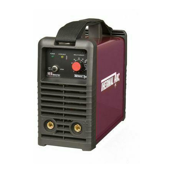
- Page 1 95 S ® THERMAL ARC INVERTER ARC WELDER Art # A-08597_AB Operating Manual Revision: AB Issue Date: March 26, 2009 Manual No.: 0-5086 Operating Features:...
- Page 2 YOU ARE IN GOOD COMPANY! The Brand of Choice for Contractors and Fabricators Worldwide. Thermal Arc is a Global Brand of Arc Welding Products for Thermadyne Industries Inc. We manufacture and supply to major welding industry sectors worldwide including; Manufacturing, Construction, Mining, Automotive, Aerospace, Engineering, Rural and DIY/Hobbyist.
- Page 3 Operating Manual Number 0-5086 for: Thermal Arc 95 S Power Source Arc Welder Part No. W1003200 Thermal Arc 95 S System with Stick Kit & Case Part No. W1003202 Thermal Arc 95 S System with Stick/TIG Kit & Case Part No. W1003203 Published by: Thermadyne Industries Inc.
-
Page 4: Table Of Contents
TABLE OF CONTENTS SECTION 1:SAFETY INSTRUCTIONS AND WARNINGS ..........1-1 1.01 Arc Welding Hazards ..................1-1 1.02 Principal Safety Standards ................1-4 1.03 Symbol Chart ....................1-5 1.04 Precautions De Securite En Soudage A L’arc ..........1-6 1.05 Dangers relatifs au soudage à l’arc ..............1-6 1.06 Principales Normes De Securite .............. - Page 5 TABLE OF CONTENTS SECTION 5:SERVICE ..................5-1 5.01 Maintenance and Inspection ................5-1 5.02 STICK Welding Problems ................5-2 5.03 TIG Welding Problems ................... 5-3 5.04 Power Source Problems ................5-4 APPENDIX 1: REPLACEMENT PARTS ..............A-1 APPENDIX 2: OPTIONS AND ACCESSORIES ............A-2 APPENDIX 3: system schematic .................
-
Page 7: Section 1:Safety Instructions And Warnings
SAFETY INSTRUCTIONS THERMAL ARC 95 S SECTION 1: SAFETY INSTRUCTIONS AND WARNINGS WARNING PROTECT YOURSELF AND OTHERS FROM POSSIBLE SERIOUS INJURY OR DEATH. KEEP CHILDREN AWAY. PACEMAKER WEARERS KEEP AWAY UNTIL CONSULTING YOUR DOCTOR. DO NOT LOSE THESE INSTRUCTIONS. READ OPERATING/INSTRUCTION MANUAL BEFORE INSTALLING, OPERATING OR SERVICING THIS EQUIPMENT. - Page 8 THERMAL ARC 95 S SAFETY INSTRUCTIONS WARNING WARNING WELDING can cause fire or explosion. FUMES AND GASES can be hazardous to your health. Sparks and spatter fly off from the welding arc. The flying Welding produces fumes and gases. Breathing these sparks and hot metal, weld spatter, hot workpiece, and fumes and gases can be hazardous to your health.
- Page 9 SAFETY INSTRUCTIONS THERMAL ARC 95 S WARNING WARNING FLYING SPARKS AND HOT METAL can cause injury. ENGINE FUEL can cause fire or explosion. Chipping and grinding cause flying metal. As welds cool, Engine fuel is highly flammable. they can throw off slag.
-
Page 10: Principal Safety Standards
THERMAL ARC 95 S SAFETY INSTRUCTIONS ABOUT PACEMAKERS: WARNING The above procedures are among those also normally STEAM AND PRESSURIZED HOT COOLANT can burn recommended for pacemaker wearers. Consult your face, eyes, and skin. doctor for complete information. The coolant in the radiator can be very hot and under 1.02... -
Page 11: Symbol Chart
SAFETY INSTRUCTIONS THERMAL ARC 95 S 1.03 Symbol Chart Note that only some of these symbols will appear on your model. Wire Feed Function Single Phase Wire Feed Towards Workpiece With Three Phase Output Voltage Off. Three Phase Static Frequency Converter-... -
Page 12: Precautions De Securite En Soudage A L'arc
THERMAL ARC 95 S SAFETY INSTRUCTIONS 1.04 Precautions De Securite En Soudage A L’arc MISE EN GARDE LE SOUDAGE A L’ARC EST DANGEREUX PROTEGEZ-VOUS, AINSI QUE LES AUTRES, CONTRE LES BLESSURES GRAVES POSSIBLES OU LA MORT. NE LAISSEZ PAS LES ENFANTS S’APPROCHER, NI LES PORTEURS DE STIMULATEUR CARDIAQUE (A MOINS QU’ILS N’AIENT CONSULTE UN MEDECIN). - Page 13 SAFETY INSTRUCTIONS THERMAL ARC 95 S 1. Portez une casque de soudeur avec filtre oculaire de nuance ap- 1. Eloignez la tête des fumées pour éviter de les respirer. propriée (consultez la norme ANSI Z49 indiquée ci-après) pour 2. A l’intérieur, assurez-vous que l’aire de soudage est bien ventilée vous protéger le visage et les yeux lorsque vous soudez ou que...
- Page 14 THERMAL ARC 95 S SAFETY INSTRUCTIONS AVERTISSEMENT AVERTISSEMENT LE SOUDAGE PEUT CAUSER UN INCENDIE OU UNE LES BOUTEILLES ENDOMMAGEES PEUVENT EX- EXPLOSION PLOSER L’arc produit des étincellies et des projections. Les parti- Les bouteilles contiennent des gaz protecteurs sous cules volantes, le métal chaud, les projections de soudure haute pression.
-
Page 15: Principales Normes De Securite
SAFETY INSTRUCTIONS THERMAL ARC 95 S 2. Ne faites pas le plein en fumant ou proche d’une source d’étincelles ou d’une flamme nue. 3. Si c’est possible, laissez le moteur refroidir avant de faire le plein AVERTISSEMENT de carburant ou d’en vérifier le niveau au début du soudage. -
Page 16: Graphique De Symbole
THERMAL ARC 95 S SAFETY INSTRUCTIONS 1.07 Graphique de Symbole Seulement certains de ces symboles apparaîtront sur votre modèle. Déroulement du Fil Sous Tension Mono Phasé Alimentation du Fil Vers la Pièce de Fabrication Hors Tension Trois Phasé Hors Tension... -
Page 17: Section 2:Introduction
INTRODUCTION THERMAL ARC 95 S SECTION 2: INTRODUCTION 2.01 How to Use This Manual 2.04 Description This Operating Manual usually applies to the part numbers This compact inverter welding machine has infinitely listed on page i. If none are underlined, they are all covered adjustable welding current from 5 to 95 amps. -
Page 18: Specifications
630, National Electrical Code). Thermal Arc continuously strives to produce the best product possible and therefore reserves the right to change, improve or revise the specifi cations or design of this or any product without prior notice. Such updates or changes do not entitle the buyer of equipment previously sold or shipped to the corresponding changes, updates, improvements or replacement of such items. -
Page 19: Section 3:Installation
• In areas, not exposed to direct sunlight or rain. • Place at a distance of 12” (300mm) or more from walls or similar that could restrict natural air flow for cooling WARNING Thermal Arc advises that this equipment be electrically connected by a qualified electrician. Installation Manual 0-5086... - Page 20 THERMAL ARC 95 S INSTALLATION Refer to Figure 3-1: 1. Connect end of ground (GREEN or GREEN/YELLOW) conductor to a suitable ground. Use a grounding method that complies with all applicable electrical codes. 2. Connect ends of line 1 (BLACK) and line 2 (WHITE) input conductors to a de-energized line disconnect switch.
- Page 21 INSTALLATION THERMAL ARC 95 S Input Power Each unit incorporates an INRUSH circuit. When the MAIN CIRCUIT SWITCH is turned on, the inrush circuit provides pre-charging for the input capacitors. A relay in the Power Control Assembly (PCA) will turn on after the input capacitors...
-
Page 22: Electromagnetic Compatibility
THERMAL ARC 95 S INSTALLATION 3.04 Electromagnetic Compatibility 8. The immunity of other equipment in the environment: the user shall ensure that other equipment being used in the environment is compatible: this may require additional protection measures. WARNING The size of the surrounding area to be considered will... -
Page 23: Setup For Welding
INSTALLATION THERMAL ARC 95 S 3.05 Setup for Welding 5. Earthing of the Work Piece Where the work piece is not bonded to earth for electri- NOTE cal safety, nor connected to earth because of its size Conventional operating procedures apply and position, e.g. -
Page 24: Stick (Smaw) Setup
THERMAL ARC 95 S INSTALLATION 3.06 STICK (SMAW) Setup Set Welding Current as specified by the Set Process Selection Electrode Manufacturer. Switch to Stick. Negative Output Positive Output Terminal Terminal (Dinse™ 25) (Dinse™ 25) Art #: A-08602 Figure 3-2: Setup for STICK Welding 3. -
Page 25: Lift Tig (Gtaw) Setup
INSTALLATION THERMAL ARC 95 S 3.07 Lift TIG (GTAW) Setup Set Process Selection Switch to LIFT TIG. Set Welding Current as specified by the Electrode Manufacturer. Negative Output Terminal (Dinse™ 25) Secure the gas cylinder in an Positive Output upright position by chaining it... - Page 26 THERMAL ARC 95 S INSTALLATION 9. Set the “Process Selection Switch” to LIFT TIG 10. Set the weld current control knob to the desired amperage. 11. The tungsten must be ground to a blunt point in order to achieve optimum welding results. It is critical to grind the tungsten electrode in the direction the grinding wheel is turning.
-
Page 27: Section 4:Operation
OPERATION THERMAL ARC 95 S SECTION 4: OPERATION Conventional operating procedures apply when using (C) Over Heat Indicator the Welding Power Source, i.e. connect work lead The welding power source is protected by a self resetting directly to work piece and electrode lead is used to hold thermostat. -
Page 28: Smaw Electrode Polarity
THERMAL ARC 95 S OPERATION 4.02 SMAW Electrode Polarity Cast Iron Most types of cast iron, except white iron, are weldable. Stick electrodes are generally connected to the "+" Positive White iron, because of its extreme brittleness, generally Output Terminal and the work lead to the "−" Negative cracks when attempts are made to weld it. -
Page 29: Gtaw Electrode Polarity
OPERATION THERMAL ARC 95 S 4.04 GTAW Electrode Polarity 4.06 Tungsten Electrode Current Ranges Connect the TIG torch to the "-" Negative Output Terminal Electrode Diameter DC Current and the work lead to the "+" Positive Output Terminal for .040" (1.0mm) 20 - 90 direct current straight polarity. -
Page 30: Arc Welding Practice
THERMAL ARC 95 S OPERATION 4.10 Arc Welding Practice The techniques used for arc welding are almost identical regardless of what types of metals are being joined. Naturally enough, different types of electrodes would be used for different metals as described in the preceding section. -
Page 31: Joint Preparations
OPERATION THERMAL ARC 95 S 4.12 Joint Preparations In many cases, it will be possible to weld steel sections without any special preparation. For heavier sections and for repair work on castings, etc., it will be necessary to cut or grind an angle between the pieces being joined to ensure proper penetration of the weld metal and to produce sound joints. -
Page 32: Arc Welding Technique
THERMAL ARC 95 S OPERATION 4.13 Arc Welding Technique is broken again. A little practice will soon remedy both of these faults. A Word to Beginners Art # A-07696 For those who have not yet done any welding, the simplest way to commence is to run beads on a piece of scrap plate. - Page 33 OPERATION THERMAL ARC 95 S a 70° to 90° included angle. This allows full penetration of B. Fillet Welds the weld metal to the root. Using a 1/8" (3.2mm) E7014 These are welds of approximately triangular cross-section electrode at 120 amps, deposit a run of weld metal on the made by depositing metal in the corner of two faces bottom of the joint.
-
Page 34: Distortion
THERMAL ARC 95 S OPERATION of the fillet. The electrode needs to be about 10° 2. Vertical Down from the horizontal to enable a good bead to be TheE7014 electrode makes welding in this position deposited. Refer Figure 4-16. Use a short arc, and particularly easy. -
Page 35: The Cause Of Distortion
OPERATION THERMAL ARC 95 S 4.20 The Cause of Distortion Art # A-07706 Distortion is cause by: A. Contraction of Weld Metal: Molten steel shrinks approximately 11 per cent in volume Figure 4-21: Parent metal contraction on cooling to room temperature. This means that a cube of molten metal would contract approximately 2.2 per... - Page 36 THERMAL ARC 95 S OPERATION E. Preheating Suitable preheating of parts of the structure other than the area to be welded can be sometimes used to reduce distortion. Figure 4-23 shows a simple application. By removing the heating source from b and c as soon as welding is completed, the sections b and c will contract at a similar rate, thus reducing distortion.
-
Page 37: Section 5:Service
SERVICE THERMAL ARC 95 S SECTION 5: SERVICE 5.01 Maintenance and Inspection To clean the unit, open the enclosure and use a vacuum cleaner to remove any accumulated dirt and dust. The unit The only routine maintenance required for the power should also be wiped clean, if necessary;... -
Page 38: Stick Welding Problems
THERMAL ARC 95 S SERVICE 5.02 STICK Welding Problems Description Possible Cause Remedy 1. Gas pockets or voids in weld metal Electrodes are damp. A. Dry electrodes before use. (Porosity). Welding current is too high. B. Reduce welding current. Surface impurities such as oil, C. -
Page 39: Tig Welding Problems
SERVICE THERMAL ARC 95 S 5.03 TIG Welding Problems Weld quality is dependent on the selection of the correct consumables, maintenance of equipment and proper welding technique. Description Possible Cause Remedy 1. Excessive beard build-up or poor Welding current is too low... -
Page 40: Power Source Problems
There are extremely dangerous voltages and power levels present inside this product. Do not attempt to repair unless you are an Accredited Thermal Arc Service Agent and you have had training in power measurements and troubleshooting techniques. If major complex subassemblies are faulty, then the Welding Power Source must be returned to an Accredited Thermal Arc Service Agent for repair. -
Page 41: Appendix 1: Replacement Parts
APPENDIX THERMAL ARC 95 S APPENDIX 1: REPLACEMENT PARTS Description Part No. Fan, 24V DC, 95S W7003004 Rectifier Bridge, 700V, 50A, 95S W7003010 Current Sensor, 95S W7003013 Thermistor, 95S W7003016 Terminal, Output, 95S W7003019 Handle, 95S W7003040 Knob, Control, Red, 20 OD x 6 ID... -
Page 42: Appendix 2: Options And Accessories
THERMAL ARC 95 S APPENDIX APPENDIX 2: OPTIONS AND ACCESSORIES Description Part Number 17V style TIG Torch with 3m lead, gas valve, 25mm dinse connection and accessory kit W4012500 Argon Shielding Gas Regulator with 5/8"-18 UNF Hose Connection 600300 Power Adapter-115V,20A Socket to 15A Plug... -
Page 43: Appendix 3: System Schematic
APPENDIX THERMAL ARC 95 S APPENDIX 3: SYSTEM SCHEMATIC Art # A-09016 Appendix Manual 0-5086... - Page 44 THERMAL ARC 95 S APPENDIX This Page Intentionally Blank Manual 0-5086 Appendix...
-
Page 45: Limited Warranty
No employee, agent, or representative of Thermal Arc is authorized to change this warranty in any way or grant any other warranty, and Thermal Arc shall not be bound by any such attempt. Correction of non-conformities, in the manner and time provided herein, constitutes fulfillment of thermal’s obligations to purchaser with respect to the product. -
Page 46: Warranty Schedule
WARRANTY SCHEDULE This information applies to Thermal Arc products that were purchased in the USA and Canada. January 2009 SAFETY EQUIPMENT ARRANTY ERIOD ABOR 2 years 2 years Auto-Darkening Welding Helmet (Electronic Lens) 1 month 1 month Harness Assembly ENGINE DRIVEN WELDERS... -
Page 47: Global Customer Service Contact Information
GLOBAL CUSTOMER SERVICE CONTACT INFORMATION Thermadyne USA Thermadyne Asia Sdn Bhd Lot 151, Jalan Industri 3/5A 2800 Airport Road Rawang Integrated Industrial Park - Jln Batu Arang Denton, Tx 76207 USA 48000 Rawang Selangor Darul Ehsan Telephone: (940) 566-2000 West Malaysia 800-426-1888 Fax: 800-535-0557 Telephone: 603+ 6092 2988... - Page 48 World Headquarters Thermadyne Holdings Corporation Suite 300, 16052 Swingley Ridge Road St. Louis, MO 63017 Telephone: (636) 728-3000 FAX: (636) 728-3010 Email: sales@thermalarc.com www.thermalarc.com...
Need help?
Do you have a question about the 95S Thermal Arc and is the answer not in the manual?
Questions and answers
The Yellow light turns on soon as you tried to well and he doesn’t go away supposed to be the overheat light but never cools down so can be used the welder is any parts to replace?
The Thermal Arc 95S welder has a self-resetting thermostat that protects it from overheating. If the yellow overheat light stays on and the welder does not cool down, possible components to check or replace include the thermostat itself or internal cooling components such as the fan. However, no specific replacement parts are listed in the provided information.
This answer is automatically generated