Sign In
Upload
Download
Table of Contents
Contents
Add to my manuals
Delete from my manuals
Share
URL of this page:
HTML Link:
Bookmark this page
Add
Manual will be automatically added to "My Manuals"
Print this page
×
Bookmark added
×
Added to my manuals
Manuals
Brands
Thermal Arc Manuals
Welding System
Fabricator 140
Service manual
Thermal Arc Fabricator 140 Service Manual
Thermal arc fabricator 140; fabricator 180 welding machine
Hide thumbs
1
2
3
Table Of Contents
4
5
6
7
8
9
10
11
12
13
14
15
16
17
18
19
20
21
22
23
24
25
26
27
28
29
30
31
32
33
34
35
36
37
38
39
40
41
42
43
44
45
46
47
48
49
50
51
52
53
54
55
56
57
58
59
60
61
62
63
64
65
66
67
68
69
70
71
72
73
74
75
76
77
78
79
80
81
82
83
84
page
of
84
Go
/
84
Contents
Table of Contents
Troubleshooting
Bookmarks
Table of Contents
Service Manual
Table of Contents
Section 1
Safety Instructions and Warnings
Arc Welding Hazards
Safety Instructions
Principal Safety Standards
Symbol Chart
Precautions de Securite en Soudage a L'arc
Dangers Relatifs Au Soudage À L'arc
Principales Normes de Securite
Graphique de Symbole
Section 2
Introduction
How to Use this Manual
Equipment Identification
Receipt of Equipment
General
Machine Specifications
Volt - Amp Curves
Duty Cycle
Fabricator 180A MIG Gun
Installing a New Wire Liner
MIG Gun Maintenance
Section 3
Installation
Location
Safety
Grounding
Electrical Input Requirements
Requirements for Maximum Output
Installation of Shielding Gas (GMAW) Process
Attaching the Gun and Cable Assembly to the Power Source
Polarity Changeover
Installing Wire Spool
Feedrolls
Install Wire into the Feedhead
Install Wire into the Welding Gun
Operation
General Safety Precautions
Fabricator Controls
Gas Metal Arc Welding (GMAW)
Flux Cored Arc Welding (FCAW)
Shutdown Procedures
Basic Welding Technique
Welding Gun Positions
MIG Welding (GMAW) Variables
Establishing the Arc and Making Weld Beads
Pre-Weld Procedure
Welding Procedure
Reference Tables
Fabricator 140 Welding Setting Selection Guide
Fabricator 180 Welding Setting Selection Guide
Gas Selection for Gas Metal Arc Welding
Basic Troubleshooting
Cleaning of the Unit
Cleaning of the Feed Rolls
Solving Problems Beyond the Welding Terminals
Welding Problems
Power Source Problems
Advanced Troubleshooting
Pre Power-Up Checks
Initial Setup Conditions
Primary Power Test
Logic & Control Test
Spool Gun Control Test
Output Voltage Test
Wire Feed & Weld Test
Primary Power Problems
Logic & Control Problems
Wire Feed and Weld Problems
Rectifier Assembly Test Procedure
T1 Transformer Test Procedure
C1 & C2 Test Procedure
Section 7
Parts List
Equipment Identification
How to Use this Parts List
Front Panel
Rear Panel
Power Supply
Wire Feeder Parts
Feed Plate Parts
Accessories
Appendix 1: Options and Accessories
Appendix 2: Fabricator 180 System Schematic
Appendix 3: Fabricator 140 System Schematic
Appendix 4: Feed Roll Kits
Limited Warranty
Warranty Schedule
Global Customer Service Contact Information
Advertisement
Quick Links
1
Service Manual
2
Machine Specifications
3
Fabricator 180A Mig Gun
4
Parts List
5
Wire Feeder Parts
Download this manual
140
180
Service Manual
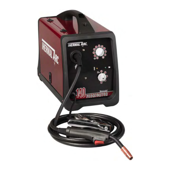
FABRICATOR
PORTABLE MIG WELDING MACHINE
Revision No: AA
Operating Features:
®
Art # A-07923
Issue Date: January 25, 2008
Manual No.: 0-4992
Table of
Contents
Previous
Page
Next
Page
1
2
3
4
5
Advertisement
Table of Contents
Troubleshooting
BASIC TROUBLESHOOTING
51
ADVANCED TROUBLESHOOTING
57
Need help?
Do you have a question about the Fabricator 140 and is the answer not in the manual?
Ask a question
Questions and answers
Related Manuals for Thermal Arc Fabricator 140
Welding System Thermal Arc FABRICATOR 181i Operating Manual
Multi process welding inverter (80 pages)
Welding System Thermal Arc 181i Fabricator Service Manual
3 in 1 multi-process welding system (106 pages)
Welding System Thermal Arc Fabricator 181i Operating Manual
3 in 1 multi-process welding systems (100 pages)
Welding System Thermal Arc 161 S Operating Manual
Inverter arc welder (56 pages)
Welding System Thermal Arc ARC MASTER 175 TE Operating Manual
Arc master inverter arc welder (52 pages)
Welding System Thermal Arc 161 STL Service Manual
Inverter arc welde (96 pages)
Welding System Thermal Arc FABRICATOR 190 Operating Manual
Mig welding machine (64 pages)
Welding System Thermal Arc 190 Fabricator Service Manual
Mig welding machine (90 pages)
Welding System Thermal Arc 155 SE User Manual
(22 pages)
Welding System Thermal Arc 175 SE ARC MASTER Operating Manual
Inverter arc welder (44 pages)
Welding System Thermal Arc 160 TS ARCMASTER Service Manual
Inverter arc welder (114 pages)
Welding System Thermal Arc 185 AC Service Manual
Inverter arc welders (122 pages)
Welding System Thermal Arc ARCMASTER 185 AC/DC Operating Manual
Inverter arc welder (74 pages)
Welding System Thermal Arc 186 AC Setup Manual
(16 pages)
Welding System Thermal Arc 186 DC Setup Manual
(16 pages)
Welding System Thermal Arc Raider 10,000 Pro K Owner's Manual
Thermal arc dc cc/cv welding generator, stick, mig, auxiliary power (33 pages)
This manual is also suitable for:
Fabricator 180
Table of Contents
Print
Rename the bookmark
Delete bookmark?
Delete from my manuals?
Login
Sign In
OR
Sign in with Facebook
Sign in with Google
Upload manual
Upload from disk
Upload from URL


Need help?
Do you have a question about the Fabricator 140 and is the answer not in the manual?
Questions and answers