
Related Manuals for Thermal Arc Firepower FP-95


Summary of Contents for Thermal Arc Firepower FP-95
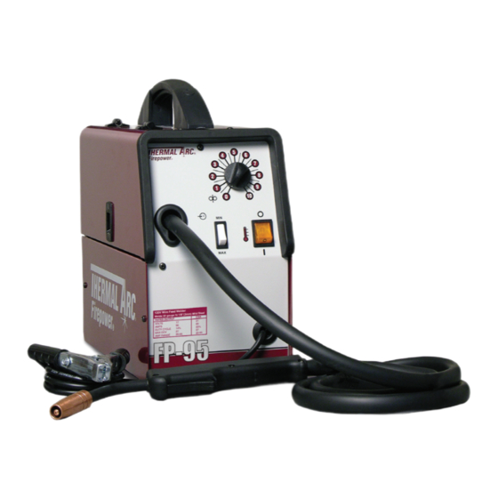
- Page 1 FP-95 MINI MIG Portable MIG Welder Art # A-09089 operating Manual Revision: AA Issue Date: March 19, 2009 Manual No.: 0-5122 Operating Features:...
- Page 2 YOU ARE IN GOOD COMPANY! The Brand of Choice for Contractors and Fabricators Worldwide. Thermal Arc is a Global Brand of Arc Welding Products for Thermadyne Industries Inc. We manufacture and supply to major welding industry sectors worldwide including; Manufacturing, Construction, Mining, Automotive, Aerospace, Engineering, Rural and DIY/Hobbyist.
- Page 3 WARNINGS Read and understand this entire Manual and your employer’s safety practices before installing, operating, or servicing the equipment. While the information contained in this Manual represents the Manufacturer’s best judgement, the Manufacturer assumes no liability for its use. Operating Manual Number 0-5122 for: FirePower 95 Mini MIG System MIG Welder Part No.
-
Page 4: Table Of Contents
4.06 Welding Gun Positions .................. 4-5 4.07 Establishing the Arc and Making Weld Beads ..........4-6 4.08 Pre-Weld Procedure ..................4-6 4.09 Welding Procedure ..................4-6 4.10 Reference Table ....................4-7 4.11 FirePower FP-95 Welding Setting Selection Guide .......... 4-8... - Page 5 TABLE OF CONTENTS SECTION 5:SERVICE ..................5-1 5.01 Cleaning of the Unit ..................5-1 5.02 Cleaning of the Feed Rolls ................5-1 5.03 Basic Troubleshooting ................... 5-1 5.04 Welding Problems ..................5-2 5.05 Power Source Problems ................. 5-3 APPENDIX 1: OPTIONS AND ACCESSORIES ............A-1 APPENDIX 2: power supply replacement parts ............
- Page 6 This Page Intentionally Blank...
-
Page 7: Section 1:Safety Instructions And Warnings
SAFETY INSTRUCTIONS FIREpOwER Fp-95 SECTION 1: SAFETY INSTRUCTIONS AND WARNINGS WARNING PROTECT YOURSELF AND OTHERS FROM POSSIBLE SERIOUS INJURY OR DEATH. KEEP CHILDREN AWAY. PACEMAKER WEARERS KEEP AWAY UNTIL CONSULTING YOUR DOCTOR. DO NOT LOSE THESE INSTRUCTIONS. READ OPERATING/INSTRUCTION MANUAL BEFORE INSTALLING, OPERATING OR SERVICING THIS EQUIPMENT. -
Page 8: Safety Instructions
FIREpOwER Fp-95 SAFETY INSTRUCTIONS WARNING WARNING WELDING can cause fire or explosion. FUMES AND GASES can be hazardous to your health. Sparks and spatter fly off from the welding arc. The flying Welding produces fumes and gases. Breathing these sparks and hot metal, weld spatter, hot workpiece, and fumes and gases can be hazardous to your health. - Page 9 SAFETY INSTRUCTIONS FIREpOwER Fp-95 WARNING WARNING FLYING SPARKS AND HOT METAL can cause injury. ENGINE FUEL can cause fire or explosion. Chipping and grinding cause flying metal. As welds cool, Engine fuel is highly flammable. they can throw off slag.
-
Page 10: Principal Safety Standards
FIREpOwER Fp-95 SAFETY INSTRUCTIONS ABOUT PACEMAKERS: WARNING The above procedures are among those also normally STEAM AND PRESSURIZED HOT COOLANT can burn recommended for pacemaker wearers. Consult your face, eyes, and skin. doctor for complete information. The coolant in the radiator can be very hot and under 1.02... -
Page 11: Symbol Chart
SAFETY INSTRUCTIONS FIREpOwER Fp-95 1.03 Symbol Chart Note that only some of these symbols will appear on your model. Wire Feed Function Single Phase Wire Feed Towards Workpiece With Three Phase Output Voltage Off. Three Phase Static Frequency Converter- Welding Gun... -
Page 12: Precautions De Securite En Soudage A L'arc
FIREpOwER Fp-95 SAFETY INSTRUCTIONS 1.04 Precautions De Securite En Soudage A L’arc MISE EN GARDE LE SOUDAGE A L’ARC EST DANGEREUX PROTEGEZ-VOUS, AINSI QUE LES AUTRES, CONTRE LES BLESSURES GRAVES POSSIBLES OU LA MORT. NE LAISSEZ PAS LES ENFANTS S’APPROCHER, NI LES PORTEURS DE STIMULATEUR CARDIAQUE (A MOINS QU’ILS N’AIENT CONSULTE UN MEDECIN). CONSERVEZ CES INSTRUCTIONS. - Page 13 SAFETY INSTRUCTIONS FIREpOwER Fp-95 1. Portez une casque de soudeur avec filtre oculaire de nuance ap- 1. Eloignez la tête des fumées pour éviter de les respirer. propriée (consultez la norme ANSI Z49 indiquée ci-après) pour 2. A l’intérieur, assurez-vous que l’aire de soudage est bien ventilée vous protéger le visage et les yeux lorsque vous soudez ou que...
- Page 14 FIREpOwER Fp-95 SAFETY INSTRUCTIONS AVERTISSEMENT AVERTISSEMENT LE SOUDAGE PEUT CAUSER UN INCENDIE OU UNE LES BOUTEILLES ENDOMMAGEES PEUVENT EX- EXPLOSION PLOSER L’arc produit des étincellies et des projections. Les parti- Les bouteilles contiennent des gaz protecteurs sous cules volantes, le métal chaud, les projections de soudure haute pression.
-
Page 15: Principales Normes De Securite
SAFETY INSTRUCTIONS FIREpOwER Fp-95 2. Ne faites pas le plein en fumant ou proche d’une source d’étincelles ou d’une flamme nue. 3. Si c’est possible, laissez le moteur refroidir avant de faire le plein AVERTISSEMENT de carburant ou d’en vérifier le niveau au début du soudage. -
Page 16: Graphique De Symbole
FIREpOwER Fp-95 SAFETY INSTRUCTIONS 1.07 Graphique de Symbole Seulement certains de ces symboles apparaîtront sur votre modèle. Déroulement du Fil Sous Tension Mono Phasé Alimentation du Fil Vers la Pièce de Fabrication Hors Tension Trois Phasé Hors Tension Tri-Phase Statique... -
Page 17: Section 2:Introduction
Refers to possible equipment damage. Cautions will be shown in bold type. 2.04 General NOTE The FirePower FP-95 Machine is a single-phase input Offers helpful information concerning certain welding machine and comes equipped with the follow- operating procedures. Notes will be shown... -
Page 18: Handle And Foot Assembly
FIREpOwER Fp-95 INTRODUCTION 2.05 Handle and Foot Assembly Art # A-09101 2.06 Specifications Description Firepower FP-95 Package System Part Number 1444-0322 Power Source Weight 37.15 lb ( 16.8 kg) Power Source Dimensions HxWxD 14"x7"x15" (355.6 x 177.8 x 381mm) Number of Phases 1 Ø... -
Page 19: Volt - Amp Curves
(Based on Article 630, National Electrical Code) Thermal Arc continuously strives to produce the best product possible and therefore reserves the right to change, improve or revise the specifications or design of this or any product without prior notice. Such updates or changes do not entitle the buyer of equipment previously sold or shipped to the corresponding changes, updates, improvements or replacement of such items. -
Page 20: Duty Cycle
85 amps. This means that it has been designed and built to provide the rated amperage, 85 amps, for1.7 minutes out of every 10 minute period. During the other 8.3 minutes of the 10 minute period, the FirePower FP-95 must idle and be allowed to cool. -
Page 21: Section 3:Installation
FIREpOwER Fp-95 SECTION 3: INSTALLATION 3.01 Location The Firepower FP-95's power cord is equipped with a NEMA 5-15P plug and will only connect to a NEMA 5-15P For best operating characteristics and longest unit life, receptacle. take care in selecting the installation site. Avoid locations exposed to high humidity, dust, high ambient temperature, or corrosive fumes. -
Page 22: Requirements For Maximum Output
FIREpOwER Fp-95 INSTALLATION 3.05 Requirements for Maximum Output Spring In order to obtain the maximum output capability of the D-Ring FirePower 95, a branch circuit capable of 20 amperes at Wire Spool 115 to 125 Volts 60 Hz is required. This generally applies when welding steel that is equal to or greater than 12 gauge (0.105”... -
Page 23: Feedrolls
Pressure Arm A feedroll consists of two different sized grooves. As delivered from the factory, the drive roll is installed for .030" (0.8mm) Firepower FP-95. Gun Cable The branding inside at the end of the feedroll refers to the size nearest to the mark This also applies to optional feedrolls which are available for this machine. - Page 24 FIREpOwER Fp-95 INSTALLATION 3. Open Pressure Arm (Fig. 3-4). Pressure Adjust Device Pressure Arm 4. Place the end of the wire into the Inlet Wire Guide, feeding it over the Feedroll. Make certain that the proper groove is being used (Fig. 3-5).
-
Page 25: Install Wire Into The Welding Gun
INSTALLATION FIREpOwER Fp-95 3.09 Install Wire into the Welding Gun 5. Activate the gun switch until the wire feeds out past the gun nozzle and deactivate the gun 1. Plug the Welding Power Source into the 120VAC switch. receptacle. Nozzle... - Page 26 FIREpOwER Fp-95 INSTALLATION This Page Intentionally Blank Manual 0-5122 Installation...
-
Page 27: Section 4:Operation
OpERATION FIREpOwER Fp-95 SECTION 4: OPERATION 4.01 General Safety Precautions Read and understand the safety instructions at the beginning of this manual prior to operating this machine. WARNING Be sure to put on proper protective clothing and eye safeguards (welding coat, apron, gloves, and welding helmet, with proper lenses installed). -
Page 28: Firepower Controls
FIREpOwER Fp-95 OpERATION NOTE 4.02 FirePower Controls Genuine TWECO contact tips should be used. Refer to Figure 4-1 1. Power ON / OFF switch turns the power on and CAUTION off. It also lights when the power supply has gone into overtemp. - Page 29 OpERATION FIREpOwER Fp-95 120V Wire Feed Welder Welds 22 gauge to 1/8" (3.2mm) Mild Steel RATED OUTPUT VOLTS 17.3 AMPS DUTY CYCLE MAX OCV AMP RANGE 23-90 23-90 FP-95 Art # A-09064 Figure 4-1: FirePower Controls Operation Manual 0-5122...
-
Page 30: Flux Cored Arc Welding (Fcaw)
FIREpOwER Fp-95 OpERATION 4.03 Flux Cored Arc Welding (FCAW) 4.04 Shutdown Procedures See Welding Guidelines included in this manual. Place the POWER ON/OFF SWITCH in the OFF position. 1. Make all necessary connections as instructed in the INSTALLATION chapter. WARNING 2. -
Page 31: Welding Gun Positions
OpERATION FIREpOwER Fp-95 Flux-Cored Arc welding (FCAw) The electrode wire is not energized until the gun trigger switch is depressed. The wire may therefore be placed on This process also known as Open Arc, Innershield, FAB the seam or joint prior to lowering the helmet. -
Page 32: Establishing The Arc And Making Weld Beads
FIREpOwER Fp-95 OpERATION 4.07 Establishing the Arc and Making 4.09 Welding Procedure Weld Beads 1. Maintain the tip to work distance (stickout) at 5/16” to 3/8” (8 to 9mm) at all times. Before attempting to weld on a finished piece of work, it is recommended that practice welds be made on a sample 2. -
Page 33: Reference Table
OpERATION FIREpOwER Fp-95 4.10 Reference Table The following table is provided as a user aid when performing FLUX CORED welding. Result Desired Welding Variable Welding Current Travel Wire Voltage (wire speed) Speed Nozzle Angle Stick out size Deeper Trailing Max... -
Page 34: Firepower Fp-95 Welding Setting Selection Guide
FIREpOwER Fp-95 OpERATION 4.11 FirePower FP-95 Welding Setting Selection Guide Material Wire Shielding Gas Wire Size and Flow Rate (Diameter) Type Type .030" (0.8mm) None Flux Core Steel E71T-GS Required .035" (0.9mm) Art # A-09033 THICKNESS L (MIN) Voltage Step... -
Page 35: Section 5:Service
If major components are faulty, then the Power Source to the pressure roller adjuster. Slag can also should be returned to an Accredited THERMAL ARC Ser- be produced by the wire passing through an vice Agent for repair. -
Page 36: Welding Problems
Slow the cooling rate by preheating part to be welded or cool slowly. 7 Cold weld puddle A Faulty rectifier unit A Have an Accredited THERMAL ARC Service Agent to test then replace the faulty component. B Loose welding cable con- B Check all welding cable connections. -
Page 37: Power Source Problems
A Primary fuse is blown. A Replace primary fuse. ON. Welding arc can not be established. B Broken connection in pri- B Have an Accredited THERMAL ARC Service Agent check mary circuit. primary circuit. Primary line voltage is MIG Gun trigger switch leads Reconnect. - Page 38 FIREpOwER Fp-95 SERVICE This Page Intentionally Blank Manual 0-5122 Service...
-
Page 39: Appendix 1: Options And Accessories
FIREpOwER Fp-95 APPENDIX 1: OPTIONS AND ACCESSORIES • Contact your Thermal Arc distributor to order options and accessories. For assistance in locating a Thermal Arc distributor, contact the Thermadyne office listed in the inside rear cover that is nearest to you. -
Page 40: Appendix 2: Power Supply Replacement Parts
FIREpOwER Fp-95 AppENDIX APPENDIX 2: POWER SUPPLY REPLACEMENT PARTS ITEM DESCRIPTION PART NO. CABLE CLAMP FOR CABLE DIAM.6+ SCREW 1444-0806 CABLE CLAMP, FP-95/125/135 1444-0807 DOOR LATCH 1444-0426 INPUT POWER CABLE, FP-95/125/135 1444-0433 PLASTIC HINGE FOR SIDE PANEL 1444-0435 YELLOW PILOT-LIGHT SWITCH... - Page 41 AppENDIX FIREpOwER Fp-95 120V Wire Feed Welder Welds 22 gauge to 1/8" (3.2mm) Mild Steel RATED OUTPUT VOLTS 17.3 AMPS DUTY CYCLE MAX OCV FP-95 AMP RANGE 23-90 23-90 Art # A-09067 Figure A-2: FP-95 Parts List Callouts Appendix Manual 0-5122...
-
Page 42: Appendix 3: Firepower 95 System Schematic
FIREpOwER Fp-95 AppENDIX APPENDIX 3: FIREPOWER 95 SYSTEM SCHEMATIC Art # A-09025 Figure A-3: FP-95 Simple System Schematic Manual 0-5122 Appendix... - Page 43 Statement of Warranty (as of March 15, 2009) LImIteD Warranty: THERMADYNE warrants that its products will be free of defects in workmanship or material. Should any failure to conform to this warranty appear within the time period applicable to the THERMADYNE products as stated below, THERMADYNE shall, upon written notification thereof and substantiation that the product has been stored, installed, operated, and maintained in accordance with THERMADYNE’s specifications, instructions, recommendations and recognized standard industry practice, and not been subject to misuse, repair, neglect,...
- Page 44 All Other Original Circuits and Components Including, but not Limited to, Relays, 1 year / 1 year Switches, Contactors, Solenoids, Fans, Power Switch Semi-Conductors Engines and Associated Components are NOT Warranted by Thermal Arc ® See the Engine Although Most are Warranted by the Engine Manufacturer. SEE THE ENGINE Manufacturers’...
-
Page 45: Global Customer Service Contact Information
GLOBAL CUSTOMER SERVICE CONTACT INFORMATION Thermadyne USA Thermadyne Asia Sdn Bhd Lot 151, Jalan Industri 3/5A 2800 Airport Road Rawang Integrated Industrial Park - Jln Batu Arang Denton, Tx 76207 USA 48000 Rawang Selangor Darul Ehsan Telephone: (940) 566-2000 West Malaysia 800-426-1888 Fax: 800-535-0557 Telephone: 603+ 6092 2988... - Page 46 World Headquarters Thermadyne Holdings Corporation Suite 300, 16052 Swingley Ridge Road St. Louis, MO 63017 Telephone: (636) 728-3000 FAX: (636) 728-3010 Email: sales@thermalarc.com www.thermalarc.com...
Need help?
Do you have a question about the Firepower FP-95 and is the answer not in the manual?
Questions and answers