
Related Manuals for Thermal Arc ARCMASTER 185 AC/DC


Summary of Contents for Thermal Arc ARCMASTER 185 AC/DC
- Page 1 185 AC/DC ® ARCMASTER INVERTER ARC WELDER Art # A-07227 Operating Manual Version No: 1 Issue Date: February 20, 2006 Manual No.: 0-4861 Operating Features: INVERTER PHASE GTAW SMAW...
- Page 2 YOU ARE IN GOOD COMPANY! The Brand of Choice for Contractors and Fabricators Worldwide. Thermal Arc is a Global Brand of Arc Welding Products for Thermadyne Industries Inc. We manufacture and supply to major welding industry sectors worldwide including; Manufacturing, Construction, Mining, Automotive, Aerospace, Engineering, Rural and DIY/Hobbyist.
- Page 3 While the information contained in this Manual represents the Manufacturer's best judgement, the Manufacturer assumes no liability for its use. ArcMaster 185 AC/DC Inverter Arc Welder Instruction Manual Number 0-4861 for: Part Number 10-3073 Published by: Thermadyne Industries Inc.
-
Page 4: Table Of Contents
OPERATOR CONTROLS ................4-1 4.01 ArcMaster 185 AC/DC Controls ..............4-1 4.02 Weld Process Selection for ArcMaster 185 AC/DC ......... 4-3 4.03 Weld Parameter Descriptions for ArcMaster 185 AC/DC ........ 4-4 4.04 Weld Parameters for ArcMaster 185 AC/DC ........... 4-6 4.05 Power Source Features................... - Page 5 TABLE OF CONTENTS (continued) TABLE OF CONTENTS SECTION 6: SEQUENCE OF OPERATION ................ 6-1 6.01 Stick Welding ....................6-2 6.02 AC or DC HF TIG Welding ................6-2 6.03 Slope Mode Sequence ..................6-3 6.04 Slope Mode with Repeat Sequence ..............6-3 6.05 Pulse Controls ....................
- Page 6 13.01 Equipment Identification ................13-1 13.02 How To Use This Parts List ................. 13-1 APPENDIX 1: GENERAL INFORMATION ..............A-1 APPENDIX 2: ARCMASTER 185 AC/DC INTERCONNECTION DIAGRAM ......A-2 APPENDIX 3: ARCMASTER 185 AC/DC ACCESSORIES ..........A-4 LIMITED WARRANTY WARRANTY SCHEDULE...
-
Page 7: Safety Instructions And Warnings
ARCMASTER 185 AC/DC SECTION 1: SAFETY INSTRUCTIONS AND WARNINGS WARNING PROTECT YOURSELF AND OTHERS FROM POSSIBLE SERIOUS INJURY OR DEATH. KEEP CHILDREN AWAY. PACEMAKER WEARERS KEEP AWAY UNTIL CONSULTING YOUR DOCTOR. DO NOT LOSE THESE INSTRUCTIONS. READ OPERATING/INSTRUCTION MANUAL BEFORE INSTALLING, OPERATING OR SERVICING THIS EQUIPMENT. - Page 8 ARCMASTER 185 AC/DC 3. Use protective screens or barriers to protect others from flash and glare; warn others not to watch the arc. WARNING 4. Wear protective clothing made from durable, flame-resistant material (wool and leather) and foot protection. WELDING can cause fire or explosion.
- Page 9 ARCMASTER 185 AC/DC 2. If used in a closed area, vent engine exhaust outside and away from any building air intakes. WARNING WARNING FLYING SPARKS AND HOT METAL can cause injury. Chipping and grinding cause flying metal. As welds cool, they can throw off slag.
-
Page 10: Principal Safety Standards
ARCMASTER 185 AC/DC 1.02 Principal Safety Standards Safety in Welding and Cutting, ANSI Standard Z49.1, from American WARNING Welding Society, 550 N.W. LeJeune Rd., Miami, FL 33126. Safety and Health Standards, OSHA 29 CFR 1910, from Superintendent STEAM AND PRESSURIZED HOT COOLANT can burn of Documents, U.S. -
Page 11: Precautions De Securite En Soudage À L'arc
ARCMASTER 185 AC/DC 1.03 Precautions de Securite en Soudage à l’Arc MISE EN GARDE LE SOUDAGE A L’ARC EST DANGEREUX PROTEGEZ-VOUS, AINSI QUE LES AUTRES, CONTRE LES BLESSURES GRAVES POSSIBLES OU LA MORT. NE LAISSEZ PAS LES ENFANTS S’APPROCHER, NI LES PORTEURS DE STIMULATEUR CARDIAQUE (A MOINS QU’ILS N’AIENT CONSULTE UN MEDECIN). CONSERVEZ CES INSTRUCTIONS. - Page 12 ARCMASTER 185 AC/DC AVERTISSEMENT AVERTISSEMENT LES VAPEURS ET LES FUMEES SONT DANGEREUSES LE RAYONNEMENT DE L’ARC PEUT BRÛLER LES YEUX POUR LA SANTE. ET LA PEAU; LE BRUIT PEUT ENDOMMAGER L’OUIE. Le soudage dégage des vapeurs et des fumées L’arc de soudage produit une chaleur et des rayons dangereuses à...
- Page 13 ARCMASTER 185 AC/DC 7. Ne soudez des tôles galvanisées ou plaquées au plomb ou au cadmium que si les zones à souder ont été grattées à fond, que si AVERTISSEMENT l’espace est bien ventilé; si nécessaire portez un respirateur à ad- duction d’air.
-
Page 14: Principales Normes De Securite
ARCMASTER 185 AC/DC Les accumulateurs contiennent de l’électrolyte acide et 1. Utilisez l’équipement à l’extérieur dans des aires ouvertes et bien ventilées. dégagent des vapeurs explosives. 2. Si vous utilisez ces équipements dans un endroit confiné, les 1. Portez toujours un écran facial en travaillant sur un accumu-lateur. -
Page 15: Introduction
Electronic copies of this manual can also be downloaded at no charge in Acrobat PDF format by going to the Thermal Arc web site listed below and clicking on the Literature Library link: http://www.thermalarc.com February 20, 2006... -
Page 16: Symbol Chart
ARCMASTER 185 AC/DC 2.04 Symbol Chart Note that only some of these symbols will appear on your model. Wire Feed Function Single Phase Wire Feed Towards Workpiece With Three Phase Output Voltage Off. Three Phase Static Frequency Converter- Welding Gun... -
Page 17: Description
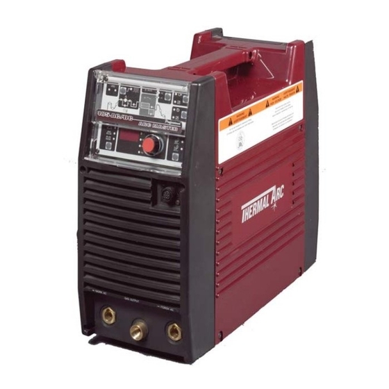
ARCMASTER 185 AC/DC 2.05 Description The Thermal Arc™ Model 185 AC/DC is a self contained Art # A-04980 single-phase AC/DC arc welding power source with Constant Current (CC) output characteristics. This unit is equipped with a Digital Volt/Amperage Meter, gas... -
Page 18: Functional Block Diagrams
ARCMASTER 185 AC/DC 2.06 Functional Block Diagrams Figure 2-2 illustrates the functional block diagram of the 185 AC/DC-power supply. DC Power Secondary To each control circuit Voltage Sensor +/-12VDC +15VDC Hall Current Input Main Input IGBT Main Output Secondary Capacitor... -
Page 19: Installation
INSTALLATION WARNING 3.01 Environment ELECTRIC SHOCK can kill; SIGNIFICANT DC VOLTAGE is present after removal of input The ArcMaster 185 AC/DC is designed for use in adverse power. environments. Examples of environments with increased adverse conditions are: DO NOT TOUCH live electrical parts. -
Page 20: Electrical Input Requirements
ARCMASTER 185 AC/DC 3.04 Electrical Input Requirements Do not connect an input (WHITE or BLACK) conductor to the ground terminal. Operate the welding power source from a single-phase Do not connect the ground (GREEN) conductor to an input 50/60 Hz, AC power supply. The input voltage must match line terminal. -
Page 21: Input Power
The ARC MASTER 185 AC/DC is designed for use with a generator as an input power source. Contact an accredited Thermal Arc service agent for the proper sizing and set-up recommendations of a generator power source system. As a general rule, depending on the type of generator used, the generator capacity should be twice the maximum rating of the welder. -
Page 22: High Frequency Interference
ARCMASTER 185 AC/DC 3.07 High Frequency Interference 3.08 Duty Cycle Interference may be transmitted by a high frequency The duty cycle of a welding power source is the percentage initiated or stabilized arc welding machine in the following of a ten (10) minute period that it can be operated at a... -
Page 23: Specifications
ARCMASTER 185 AC/DC 3.09 Specifications Parameter 185ACDC Rated Output Amperes Volts Duty Cycle Duty Cycle 185A / 18V @ 30% 160A / 17V @ 60% 100A / 14V @ 100% STICK 160A / 27V @ 40% 130A / 26V @ 60%... - Page 24 ARCMASTER 185 AC/DC NOTES February 20, 2006...
-
Page 25: Operator Controls
ARCMASTER 185 AC/DC SECTION 4: OPERATOR CONTROLS 4.01 ArcMaster 185 AC/DC Controls Art # A-04983 Figure 4-1: ArcMaster 185 AC/DC Power Source 1. Control Knob: This control sets the selected weld Socket Pin Function parameter, rotating it clockwise increases the parameter Earth (Ground) that is indicated on the digital meter. - Page 26 ARCMASTER 185 AC/DC 3. Positive Terminal: Welding current flows from the 6. ON/OFF Switch: This switch connects the Primary Power Source via heavy duty Dinse type terminal. It supply voltage to the inverter when in the ON position. is essential, however, that the male plug is inserted This enables the Power Supply.
-
Page 27: Weld Process Selection For Arcmaster 185 Ac/Dc
Pulse operation in TIG Modes. PULSE ON/OFF Selects AC or DC weld current. Contactor operation in Stick Mode. Contactor ON/OFF Selects in operation Panel board or Remote. Operation PANEL/REMOTE Table 4-2: Weld Process selection versus Weld Mode for ArcMaster 185 AC/DC February 20, 2006... -
Page 28: Weld Parameter Descriptions For Arcmaster 185 Ac/Dc
This parameter operates in TIG modes only and is used to set the time for the weld current to ramp up, after the torch trigger switch has been pressed then released, from INITIAL CUR to PEAK or BASE current. Table 4-3: ArcMaster 185 AC/DC Front Panel Parameter Description February 20, 2006... - Page 29 The SAVE/LOAD buttons are used to save and retrieve a total number of 5 programs into the 185 AC/DC memory. Table 4-3 (continued): ArcMaster 185 AC/DC Front Panel Parameter Description February 20, 2006...
-
Page 30: Weld Parameters For Arcmaster 185 Ac/Dc
3 sec 0.1 sec CRATER CUR. 5 to 200A POST-FLOW 0.0 to 60 sec 10 sec 0.1 sec Table 4-4: Weld Parameters for ArcMaster 185 AC/DC PULSE FREQ. Range Incremental Unit 0.5 to 20Hz 0.1Hz 20 to 100Hz 100 to 500Hz... -
Page 31: Power Source Features
ARCMASTER 185 AC/DC 4.05 Power Source Features Feature Description • New Digital Control Almost all welding parameters are adjustable. • Touch Panel Switches Touch switches eliminate mechanical damage. • Front Control Cover Protects front panel controls. • Digital Meter Displays selected weld parameter value. - Page 32 ARCMASTER 185 AC/DC Feature Description • Save/Load Function A total number of 5 programs can be saved into the 185AC/DC memory. SAVE the Current Weld Parameters into Memory • Press and HOLD the SAVE button. Beep will sound and the Digital Meter will show a number 1.
-
Page 33: Set-Up For Smaw (Stick) And Gtaw (Tig)
ARCMASTER 185 AC/DC SECTION 5: SET-UP FOR SMAW (STICK) AND GTAW (TIG) Conventional operating procedures apply when using the Welding Power Source, i.e. connect work lead directly to work piece and electrode lead is used to hold electrode. Wide safety margins provided by the coil design ensure that the Welding Power Source will withstand short-term overload without adverse effects. - Page 34 ARCMASTER 185 AC/DC NOTES February 20, 2006...
-
Page 35: Sequence Of Operation
ARCMASTER 185 AC/DC SECTION 6: SEQUENCE OF OPERATION Scroll Buttons are used to select the parameters to be set. The LED’s show which function is being adjusted on the weld sequence graph. Refer to the Symbols Table located in the front of the manual for Symbol descriptions. -
Page 36: Stick Welding
ARCMASTER 185 AC/DC 6.01 Stick Welding 6.02 AC or DC HF TIG Welding · Connect work lead to negative terminal · Connect work lead to positive terminal · Connect electrode lead to positive terminal · Connect TIG torch to negative terminal ·... -
Page 37: Slope Mode Sequence
ARCMASTER 185 AC/DC 6.03 Slope Mode Sequence Art # A-04989 Switch Switch Switch Switch Closed Closed Open Open Weld Current Down Slope Slope Initial Final Current Current Postflow Preflow Figure 6-2: Slope Mode Sequence NOTE Slope function operates with a Remote ON/OFF device only 1. -
Page 38: Pulse Controls
ARCMASTER 185 AC/DC 6.05 Pulse Controls (Pulse Width) (Pulse Frequency) Art # A-04990 (Peak Current) (Base) Background Current Figure 6-3: Pulse Controls The Pulse controls are used primarily to control heat input. Pulse offers a number of advantages as follows: 1) Control puddle –... -
Page 39: Basic Tig Welding Guide
ARCMASTER 185 AC/DC SECTION 7: BASIC TIG WELDING GUIDE 7.01 Explanation of “Fluttery Arc” when This idea is supported by the observation that once fluttering starts it can be made to stop by working the arc AC TIG Welding on Aluminum away from the mirror like weld pool to an area of oxide coated material. -
Page 40: Electrode Polarity
ARCMASTER 185 AC/DC 7.02 Electrode Polarity Connect the TIG torch to the - / TORCH terminal and the work lead to the + / WORK terminal for direct current straight polarity. Direct current straight polarity is the most widely used polarity for DC TIG welding. It allows limited wear of the electrode since 70% of the heat is concentrated at the work piece. -
Page 41: Guide For Selecting Filler Wire Diameter
ARCMASTER 185 AC/DC 7.05 Guide for Selecting Filler Wire Diameter NOTE The filler wire diameter specified in Table 7-4 is a guide only, other diameter wires may be used according to the welding application AC Current Range DC Current Range... -
Page 42: Welding Parameters For Aluminum
ARCMASTER 185 AC/DC 7.08 Welding Parameters for Aluminum Filler Rod Base Metal AC Current for Tungsten Argon Gas Joint Type Diameter Thickness Aluminum Electrode Flow Rate Diameter (if required) Liters/min 0.040” 30-45 0.040” 1/16” Butt/Corner 1.0mm 35-50 1.0mm 1.6mm Lap/ Fillet 0.045”... -
Page 43: Basic Arc Welding Guide
ARCMASTER 185 AC/DC SECTION 8: BASIC ARC WELDING GUIDE 8.01 Electrode Polarity Stick electrodes are generally connected to the ‘+’ terminal and the work lead to the ‘-’ terminal but if in doubt consult the electrode manufacturers literature. 8.02 Effects of Stick Welding Various... - Page 44 ARCMASTER 185 AC/DC Metals being Electrode Comments joined Mild Steel 6013 Ideal electrodes for all general purpose work. Features include outstanding operator appeal, easy arc starting and low spatter. Mild Steel 7014 All positional electrode for use on mild and galvanized steel furniture, plates, fences, gates, pipes and tanks etc.
-
Page 45: Routine Maintenance
Turn Power Switch to OFF before proceeding. Internal cleaning of the unit should be done every 6 months by an authorized Thermal Arc Service Center to remove any accumulated dirt and dust. This may need to be done more frequently under exceptionally dirty conditions. - Page 46 ARCMASTER 185 AC/DC Maintain more often Warning! if used under severe Disconnect input power before maintaining. conditions Each Use Visual check of torch Visual check of Consumable parts regulator and pressure Weekly Visually inspect the torch Visually inspect the body and consumables cables and leads.
-
Page 47: Basic Troubleshooting
WARNING There are extremely dangerous voltages and power levels present inside this product. Do not attempt to open or repair unless you are an accredited Thermal Arc Service Agent and you have had training in power measurements and troubleshooting techniques. - Page 48 ARCMASTER 185 AC/DC Description Possible Cause Remedy A Connect the electrode to the Electrode melts when Electrode is connected to the arc is struck. ‘+’ terminal. ‘−’ terminal. WAVE BALANCE WAVE BALANCE is greater Reduced than 50%. to below 50% or increase the electrode size.
- Page 49 ARCMASTER 185 AC/DC Description Possible Cause Remedy 11 Welding arc cannot A Work clamp is not connected to A Connect the work clamp to the be established. the work piece or the work/torch work piece or connect the leads are not connected to the work/torch leads to the right right welding terminals.
-
Page 50: Stick Welding Problems
ARCMASTER 185 AC/DC 10.02 Stick Welding Problems Description Possible Cause Remedy 1 Gas pockets or Electrodes are damp. Dry electrodes before use. voids in weld metal Welding current is too high. Reduce welding current. (Porosity). Surface impurities such as oil, Clean joint before welding. - Page 51 ARCMASTER 185 AC/DC Description Possible Cause Remedy 4 Portions of the weld Small electrodes used on heavy Use larger electrodes and run do not fuse to the cold plate. pre-heat the plate. surface of the metal Welding current is too low.
- Page 52 ARCMASTER 185 AC/DC Description Possible Cause Remedy 5 Non-metallic particles A Non-metallic particles may be A If bad undercut is present, clean are trapped in the trapped in undercut from slag out and cover with a run weld metal (slag previous run.
-
Page 53: Power Source Problems
ARCMASTER 185 AC/DC 10.03 Power Source Problems Description Possible Cause Remedy 1 The welding arc The Primary supply voltage has Switch ON the Primary cannot be not been switched ON. supply voltage. established. The Welding Power Source Switch ON the Welding switch is switched OFF. - Page 54 ARCMASTER 185 AC/DC Description Possible Cause Remedy SLOPE 5 Gas flow won’t A Weld Mode ( A Strike an arc to complete the shut OFF. REPEAT SPOT ) was changed weld cycle. POST-FLOW before gas time had finished. Switch machine OFF then ON to reset solenoid valve sequence.
-
Page 55: Voltage Reduction Device (Vrd)
In addition to the above tests and specifically in relation to the VRD fitted to this machine, the following periodic tests should also be conducted by an accredited Thermal Arc service agent. Description IEC 60974-1 Requirements VRD Open Circuit Voltage Less than 20V;... -
Page 56: Switching Vrd On/Off
ARCMASTER 185 AC/DC 11.03 SWITCHING VRD ON/OFF Switch the machine OFF. A) Remove the clear plastic cover from the control panel. (see Figure 11-1) 1 Lift up the cover so it rests on the top of the unit. 2 Place a small flat bladed screw driver between the cover hinge on the front panel. - Page 57 ARCMASTER 185 AC/DC C) Access the VRD control by gently prying back the front panel controls to reveal the VRD ON/OFF potentiometer. (see Figure 11-3) D) Turning the VRD ON/OFF. (see Figure 11-3) • To turn VRD ON: rotate the trim potentiometer on the display PCB fully clockwise. When VRD is turned ON check that it operates as per VRD Specifications on page 11-1.
- Page 58 ARCMASTER 185 AC/DC NOTES 11-4 February 20, 2006...
-
Page 59: Power Source Error Codes
ARCMASTER 185 AC/DC SECTION 12: POWER SOURCE ERROR CODES Description Possible Cause Remedy Remarks A The Welding Power A Let Power Source 1 E01 error code Weld current Source’s duty cycle cool down then displayed ceases. Buzzer has been exceeded. - Page 60 ARCMASTER 185 AC/DC E11 error code Primary supply Have an accredited Weld current ceases. displayed voltage is greater Thermal Arc Service Buzzer sounds Over Primary supply than the nominal Agent or a qualified contstantly. (input) voltage at voltage plus 10%.
- Page 61 ARCMASTER 185 AC/DC E82 error code The Primary supply Have an accredited No weld current is displayed (input) voltage Thermal Arc Service available. Buzzer Rated voltage fluctuates and is Agent or a qualified sounds constantly. selection circuit not stable. electrician check the Switch machine OFF abnormality.
- Page 62 ARCMASTER 185 AC/DC E94 error code The Welding Power Have an accredited Weld current ceases. displayed Source’s Thermal Arc Service Buzzer sounds Temperature sensor temperature Agent check or constantly. Switch TH1 for IGBTs or sensors have replace the machine OFF.
-
Page 63: Parts List
ARCMASTER 185 AC/DC SECTION 13: PARTS LIST 13.01 EQUIPMENT IDENTIFICATION 13.02 HOW TO USE THIS PARTS LIST All identification numbers as described in the Introduc- The Parts List is a combination of an illustration and a tion chapter must be furnished when ordering parts or corresponding list of parts which contains a breakdown making inquiries. - Page 64 ARCMASTER 185 AC/DC QTY. Description Order No. 8 pin Receptacle W7000101 Primary Switch W7000201 Panel, Upper Front W7000301 Panel, Upper Rear W7000401 Case Half W7000501 Case Front W7000601 Frame, Rear W7000701 Label, Name, 185AC/DC W7000801 Label, Side W7000901 Label, Warning...
-
Page 65: Appendix 1: General Information
ARCMASTER 185 AC/DC APPENDIX 1: GENERAL INFORMATION • Note the model and specification number shown on the equipment nameplate. February 20, 2006... -
Page 66: Appendix 2: Arcmaster 185 Ac/Dc Interconnection Diagram
ARCMASTER 185 AC/DC APPENDIX 2: ARCMASTER 185 AC/DC INTERCONNECTION DIAGRAM PCB1 Main K(7) Circuit PCB8 Board IGBT Gate G(6) [WK-5493] Circuit Board R(3) Line1 [WK-5479] S(4) Line2 T(5) Ground PCB2 Link PCB17 Circuit Filter Board Circuit Board [WK-5482] [WK-4917] PCB9... - Page 67 ARCMASTER 185 AC/DC PCB12 PCB14 DIODE Snubber IGBT Snubber Circuit Board Circuit Board [WK-5615] [WK-5570] FCH1 TB20 PCB15 TB22 IGBT Gate Circuit +Output Board TB12 Terminal [WK-3367] TB21 1 2 3 4 5 1 2 3 4 5 Ground RY+15V...
-
Page 68: Appendix 3: Arcmaster 185 Ac/Dc Accessories
ARCMASTER 185 AC/DC APPENDIX 3: ARCMASTER 185 AC/DC ACCESSORIES ACCESSORIES PART NO. DESCRIPTION Stick Kit 90925A Work clamp with 15’ cable and stick electrode with 15’ cable TIG Kit W4009105 Includes regulator/flowgauge, 12.5’ 150 Amp TIG torch & built-in rotary amperage control. -
Page 70: Limited Warranty
No employee, agent, or representative of Thermal Arc is authorized to change this warranty in any way or grant any other warranty, and Thermal Arc shall not be bound by any such attempt. -
Page 71: Warranty Schedule
WARRANTY SCHEDULE This information applies to Thermal Arc products that were purchased in the USA and Canada. April 2006 ENGINE DRIVEN WELDERS ARRANTY ERIOD ABOR Scout, Raider, Explorer Original Main Power Stators and Inductors .................. 3 years 3 years Original Main Power Rectifiers, Control P.C. Boards ..............3 years... -
Page 73: Global Customer Service Contact Information
GLOBAL CUSTOMER SERVICE CONTACT INFORMATION Thermadyne USA Thermadyne Asia Sdn Bhd 2800 Airport Road Lot 151, Jalan Industri 3/5A Rawang Integrated Industrial Park - Jln Batu Arang Denton, Tx 76207 USA 48000 Rawang Selangor Darul Ehsan Telephone: (940) 566-2000 West Malaysia 800-426-1888 Fax: 800-535-0557 Telephone: 603+ 6092 2988... - Page 74 World Headquarters Thermadyne Holdings Corporation Suite 300, 16052 Swingley Ridge Road Telephone: (636) 728-3000 Fascimile: (636) 728-3010 Email: sales@thermalarc.com www.thermalarc.com...
Need help?
Do you have a question about the ARCMASTER 185 AC/DC and is the answer not in the manual?
Questions and answers