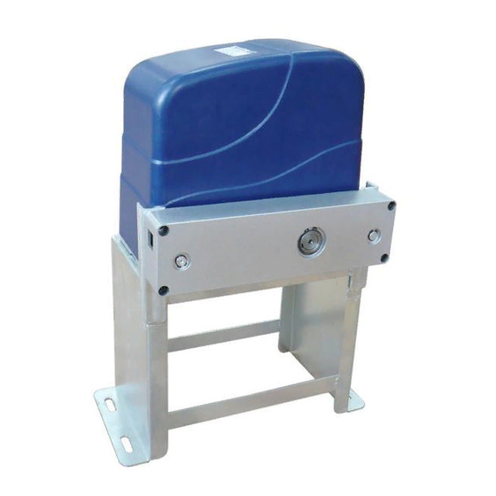
Table of Contents
Advertisement
Advertisement
Table of Contents

Summary of Contents for LockMaster DSC 600
- Page 1 www.WholesaleGateOpener.com Rev 11C...
-
Page 2: Table Of Contents
Table of Contents General Safety ……………………………………..……………………………………..………………….. 2 Preparation for Installation ……………………………………………..…………………………………..…….. 3 Parts List ………………………………………..….…………………………………..…………………………. 4 Optional Accessories Part List ………………………………………..….…………………………………..… 5 Technical Specifications & Feature …………………….……………………..…………………………………..6 Installation Overview ……………………………….…………..…………………………………..……………. 6 Installation of the Opener ……………………………………..…………………………………....……….7 Manual Operation …………………………………………..…………………………………..……………….. 7 Installation of chain and chain brackets ………………………………………..………………………………... -
Page 3: General Safety
Thank you for purchasing DSC 600/DSC 1000 sliding gate opener. We are sure that the products will be greatly satisfying as soon as you start to use it. The product is supplied with a user’s manual which encloses installation and safety precautions. These should be read carefully before installation and operation as they provide important information about safety, installation, operation and maintenance. -
Page 4: Preparation For Installation
emergency. • Do not allow persons or children to remain in the automation operation area. • Keep radio control or other control devices out of children’s reach, in order to avoid unintentional automation activation. • The user must avoid any attempt to carry out work or repair on the automation system, and always request the assistance of qualified personnel. -
Page 5: Parts List
Parts List... -
Page 6: Optional Accessories Part List
Optional Accessories Parts List... -
Page 7: Technical Specifications & Feature
·Absorbed power: 180W for DSC 600 / 350W for DSC 1000 ·Gate moving speed: 0.2 m/sec ·Max gate weight: 600KGS for DSC 600 / 1000KGS for DSC 1000 ·Max torque: 12Nm for DSC 600 / 24Nm for DSC 1000 ·Ambient: from -15°C to +40°C; Humidity: max 75% ·Protection class: IP44... -
Page 8: Installation Of The Opener
Installation of the Opener Caution: *Be sure that the opener is installed in a level and paralleled position and is properly secured. Improper installation could result in property damage, severe injury, and/or death. * Before starting installation, ensure that there is no point of friction during the entire movement of the gate and there is no danger of derailment. -
Page 9: Installation Of Chain And Chain Brackets
Installation of chain and chain brackets 1. Chain Brackets 1). Please refer to below chain brackets figure, which shows “U” bolt, “L” bracket and chain bolt. Use the “U” bolts (square or round) to attach the chain brackets to gate frame. 2). -
Page 10: Installation Of Magnets For Limit Switches
* Thoroughly fasten the four nuts as well as spring washers onto anchor bolts tightly, enabling the opener is firmly secured on the concrete pad during the whole gate travel. 3. Check position of opener and chain brackets 1). The chain brackets must be mounted to the same height as the chain on the idler wheels. 2). -
Page 11: Connecting Of Power Supply
Connecting Of Power Supply The power supply cord should be at least H05R1V-F, 3×0.75mm2. Connect the live wire, neutral wire and earth wire to the “L”, “N” and “PE” terminal respectively. It is strongly recommended that an emergency stop switch is installed in the electrical system which can be used in case of the remote control failure. -
Page 12: Connecting Of The Control Board
Connecting Of The Control Board 1. Motor The YELLOW wire of the motor should be connected into the “1” terminal. The RED wire of the motor should be connected into the “2” terminal. 2. Limit Switches The YELLOW wire of the limit switches should be connected into the “3” terminal. The BLACK wire of the limit switches should be connected into the “4”... -
Page 13: Setting Of The Control Board
The RED wire of the alarm lamp should be connected into the “7” terminal. 4. Photocell Use a 2-core cable to connect the “- ~” terminal of the photocell’s emitter to the “16” terminal, the “+ ~” terminal to the “17” terminal. Also the “- ~” and “+ ~” terminals of the photocell’s receiver should be connected to the “16”... - Page 14 DIP Switch #1–#2: Running time of the motor in Midway Mode DIP Switch #1: ON – 2 Seconds OFF – 0 DIP Switch #2: ON – 4 Seconds OFF – 0 NOTE: The midway mode function would be disabled if both DIP switches are turned off. Factory default setting is disabled.
-
Page 15: Test The Reversing Sensitivity
Test the reversing sensitivity For the sake of safety, it is very important to test the reversing sensitivity as soon as the control board set is finished. The reversing sensitivity adjustment is inverse correlation with stall force adjustment in potentiometer A and B. -
Page 16: Troubleshooting
Troubleshooting Have a multimeter to check voltage and continuity. Use caution when checking high voltage terminals. Symptom Possible Solution(s) 1. Make sure that the power cord is properly plugged into the mains outlet. 2. Check if the output voltage of the transformer is 24VAC. If the voltage The opener does not measures 0, the transformer may be overheated or damaged. -
Page 17: Maintenance
* Always check the Stop/Reverse in case of obstruction function when performing any maintenance. If this function can’t be made operable, remove this opener from service until the cause of the malfunction is identified and corrected. www.WholesaleGateOpener.com 7106 S 220th St, Kent WA 98032 USA sales@WholesaleGateOpener.com ©2010-2012 LockMaster All Rights Reserved...


Need help?
Do you have a question about the DSC 600 and is the answer not in the manual?
Questions and answers