Advertisement
Advertisement

Subscribe to Our Youtube Channel
Related Manuals for LockMaster L110C


Summary of Contents for LockMaster L110C
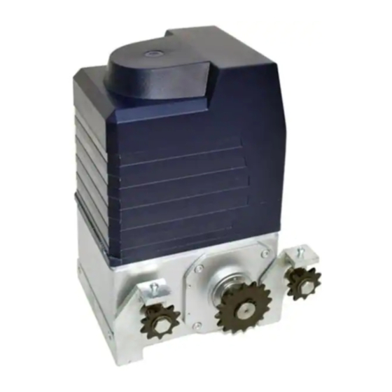
- Page 1 Sliding Gate Operator User's Manual Model: L110C www.Openers4Less.com...
-
Page 2: Table Of Contents
L110C/L110 SLIDING GATE OPERATOR OUTLINE 1. Important safety information …………………3 2. Main functions …………………………………3 3. Technical parameters …………………………3 4. Packing list ……………………………………3 5. Installation ……………………………………5 6. Connect the wires ……………………………9 7. Adjustment ……………………………………9 8. Maintenance …………………………………10... -
Page 3: Important Safety Information
-10ºC to +55ºC 4.Packing list After receiving the product, you should make an unpack-inspection, in which you should check whether the product was damaged. If you have any problem please contact dealer. L110C gate operator packing list Item Quantity Gate operator... - Page 4 Residential Sliding Gate Operator Tools you will need During assembly and installation of your opener, the instructions will call for the use of various tools shown below. Other tools may be required as needed for the installation of the concrete pad and electrical connection. Table 3 Required Tools for Installation Screwdriver Tape Measure...
- Page 5 L110C/L110 SLIDING GATE OPERATOR Fig.1 L110C accessories L110 gate operator packing list Item Quantity Gate operator Release key Operator base (spare accessory) Tighten bar Block bracket Sprocket cover Screw for mounting driven sprocket bracket (M8X16) Anchor bolt with nut Driven sprocket bracket (left side & right side)
-
Page 6: Installation
Fig.2 L110 accessories 5. Installation The L110C/L110 Chain-driven Gate Operator operates by forcing a straight piece of chain. This length of chain is extended between two chain brackets located at opposite ends of the gate. The entire configuration is shown in the diagram below. - Page 7 L110C/L110 SLIDING GATE OPERATOR Fig.4 L110 Conduit In order to protect the wires, conduit must be preset into the concrete when it is poured. Wires within the conduit shall be located or protected so that no damage can result from contact with any rough or sharp part.
- Page 8 L110C/L110 SLIDING GATE OPERATOR Driven sprocket bracket Fix the driven sprocket bracket on both sides of the operator. Operator In locations where ground freeze is possible, mount the gate operator as shown in Fig.5 installation 1 or installation 2. Check the operator and make sure it is lined up with the gate.
- Page 9 Sprocket cover Mount the sprocket cover with screws. Limit switch L110C-Magnets for limit switch (see Fig.10) Install the magnet as shown in Fig.10 below. The magnet and limit switch are used to control the position of the gate. When the magnet is installed, release the gear clutch and push the sliding gate manually to pre-determine the position.
-
Page 10: Connect The Wires
L110C/L110 SLIDING GATE OPERATOR L110-Spring limit switch (see Fig.11) To ensure safety, it is recommended to install limit devices at both ends of the gate to prevent the gate from sliding out of the rails. The rails must be installed horizontally. -
Page 11: Maintenance
L110C/L110 SLIDING GATE OPERATOR Tighten (or release) the force adjust bolt on the motor top to increase (or decrease) the output torque (i.e. output force of the operator), and ensure the gate safely. Adjust the output torque in the safety range before using the operator. - Page 12 Step #1 Unscrew the Blue Cover from the Motor and set it aside. Open the small white box & make sure that the contents include: (1) - Receiver and (1) - Control Board Step #2 Install the Control Board onto the Motor by mounting it on the small white clips that are on the large Mounting Plate.
- Page 13 MAKING THE CONNECTION Step #4 Now you will begin the installation by screwing the wires that are coming from the small Receiver Board onto the Terminals (see Pic 1, right) from the Control Board, in the following order: Terminal 10 - GREEN WIRE Terminal 11 - RED WIRE Terminal 12 - YELLOW WIRE (any) Terminal 13 - YELLOW &...
- Page 14 Step #6 Find the plug with the Blue & Yellow wires on it. Connect the plug on to the Control Board on the section labeled: "CAPACITOR" (as shown on the pic, right) Step #7 Find the plug with the Red, White & Blue wires on it. Connect the plug on to the Control Board on the section labeled: "LIMIT SWITCH"...
- Page 15 AC SLIDE GATE CONTROLLER FEATURE SELECTOR Limit Switch Type DIP 1 ON: Normally Close OFF: Normally Open When using auto close features only one dip switch should be it h h ld b Auto Close Feature Auto Close Feature DI P 2 12.5 Seconds ON.
- Page 16 Transmitter/Remote Control (shown in Figure 9) 1. Yellow Button Channel 2. Blue Button Channel 3. Indicator Light 4. Yellow Button Channel – exposed 5. DIP Switch 6. Battery 7. Blue Button Channel – exposed 8. Back side cover Figure 9 Receiver 1.
- Page 17 Residential Sliding Gate Operator Optional Equipment Installation Procedures Green Brown Black Blue Brown Black White Grey Grey Black Black...
- Page 18 ©2005-2009 LockMaster All Rights Reserved...
Need help?
Do you have a question about the L110C and is the answer not in the manual?
Questions and answers
programming new remote control
To program a new remote control for the LockMaster L110C:
1. Locate the transmitter DIP switches inside the remote control.
2. There are eight (8) DIP switches, each of which can be set to three positions (+, 0, -).
3. Choose a unique code by setting the DIP switches in any combination, but do not set them all to the same position (e.g., all +, all 0, or all -).
4. Close the remote control cover after setting the DIP switches.
5. Ensure the receiver in the gate operator has matching DIP switch settings to the remote control for proper operation.
This answer is automatically generated