
Related Manuals for LockMaster LockMaster DKC400UY


Summary of Contents for LockMaster LockMaster DKC400UY
- Page 1 Sliding Gate Operator User's Manual Lockmaster DKC400UY Lockmaster DKC400U Aleko AR1400 www.Openers4less.com Sales@Openers4less.com 352.241.8259...
- Page 2 DKC400 (U) Y SLIDING GATE OPERATOR USER’S MANUAL OUTLINE …………………………3 1. Important safety information ………………………………………3 2. Main features …………………………3 3. Main technical parameters ………………4 4. Working principle and main structure …………………………4 5. Installation and adjustment …………………………………………7 6. Connecting ……………………………………………10 7. Control ……………………………………………14 8.
- Page 3 DKC400UY...
- Page 4 DKC400UY MODEL: COMPONENT COMPONENT MFR’S PART NO. QUANTITY DESCRIPTION MANUFACTURER LockMaster Cover tr3cov1 LockMaster Set Phillips screw tr3sps2 LockMaster ½ h.p. Motor tr3mot3 LockMaster Limit magnets tr3lm4 LockMaster Control board tr3c/b5 LockMaster Capacitor tr3cap6 LockMaster Gear racks 2.3 ft. tr3gr7...
- Page 5 Residential Sliding Gate Operator Tools you will need During assembly and installation of your opener, the instructions will call for the use of various tools shown below. Other tools may be required as needed for the installation of the concrete pad and electrical connection. Table 3 Required Tools for Installation Screwdriver Tape Measure...
- Page 6 DKC400 (U) Y SLIDING GATE OPERATOR USER’S MANUAL 1. Important safety information Carefully read and follow all safety precaution and warnings before attempting to install and use this operator, incorrect installation can lead to severe injury. The gate operator should be installed by a qualified technician; otherwise, serious personal injury or property damage may occur.
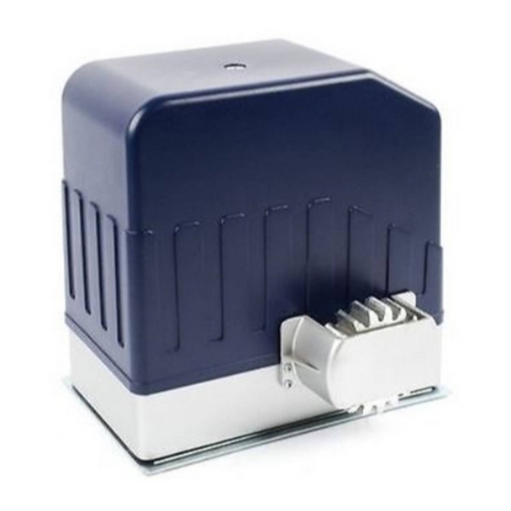
- Page 7 DKC400 (U) Y SLIDING GATE OPERATOR USER’S MANUAL Limit switch Magnetic limit switch Remote control operating range Frequency 433.92mHz Remote control mode Single-button Auto-close time 0-44 sec. Working time 90 sec. ≤62dB Noise -10ºC~+55ºC Environmental temperature 4. Working principle and main structure The device is composed of a single-phase motor, worm and worm gear.
- Page 8 DKC400 (U) Y SLIDING GATE OPERATOR USER’S MANUAL Conduit In order to protect the wires, use PVC conduit for control wires, conduit must be set into the concrete when it is poured. Wires within the conduit shall be located or protected so that no damage can result from contact with any rough or sharp part.
- Page 9 DKC400 (U) Y SLIDING GATE OPERATOR USER’S MANUAL Fig.3 Magnets for limit switch To ensure safety, it is recommended to install limit devices at both ends of the gate to prevent the gate from sliding out of the rails. The rails must be installed horizontally. Install the magnet as shown in Fig.4 and Fig.5.
- Page 10 Step #1 Unscrew the Blue Cover from the Motor and set it aside. Open the small white box & make sure that the contents include: (1) - Receiver and (1) - Control Board Step #2 Install the Control Board onto the Motor by mounting it on the small white clips that are on the large Mounting Plate.
- Page 11 MAKING THE CONNECTION Step #4 Now you will begin the installation by screwing the wires that are coming from the small Receiver Board onto the Terminals (see Pic 1, right) from the Control Board, in the following order: Terminal 10 - GREEN WIRE Terminal 11 - RED WIRE Terminal 12 - YELLOW WIRE (any) Terminal 13 - YELLOW &...
- Page 12 Step #6 Find the plug with the Blue & Yellow wires on it. Connect the plug on to the Control Board on the section labeled: "CAPACITOR" (as shown on the pic, right) Step #7 Find the plug with the Red, White & Blue wires on it. Connect the plug on to the Control Board on the section labeled: "LIMIT SWITCH"...
- Page 13 AC SLIDE GATE CONTROLLER FEATURE SELECTOR Limit Switch Type DIP 1 ON: Normally Close OFF: Normally Open When using auto close features only one dip switch should be it h h ld b Auto Close Feature Auto Close Feature DI P 2 12.5 Seconds ON.
- Page 14 Transmitter/Remote Control (shown in Figure 9) 1. Yellow Button Channel 2. Blue Button Channel 3. Indicator Light 4. Yellow Button Channel – exposed 5. DIP Switch 6. Battery 7. Blue Button Channel – exposed 8. Back side cover Figure 9 Receiver 1.
- Page 15 Residential Sliding Gate Operator Optional Equipment Installation Procedures Green Brown Black Blue Brown Black White Grey Grey Black Black...
- Page 16 DKC400 (U) Y SLIDING GATE OPERATOR USER’S MANUAL 10. Troubleshooting Trouble Possible causes Solutions Check wire connector terminal block The wire connector terminal block make sure it is plugged in terminal becomes loose. block 10, X8. Check limit switch wire connector The limit switch wire connector terminal terminal block make sure it is plugged Motor only runs in one direction.
- Page 17 ©2005-2009 LockMaster All Rights Reserved...
Need help?
Do you have a question about the LockMaster DKC400UY and is the answer not in the manual?
Questions and answers