Table of Contents
Advertisement
Advertisement
Table of Contents

Related Manuals for LockMaster SCG 18H


Summary of Contents for LockMaster SCG 18H
- Page 1 www.WholesaleGateOpener.com Rev 11a...
-
Page 2: Table Of Contents
Table of Contents General Safety ……………………………………..……………………………………..………………….. 2 Important Safety Instructions ……………………………………………..…………………………………..… 3 Preparation for Installation ……………………………………………..…………………………………..…….. 5 Parts List ………………………………………..….…………………………………..…………………………. 6 Optional Accessories Part List ………………………………………..….…………………………………..… 7 Technical Specifications & Feature …………………….……………………..…………………………………..7 Installation Overview ……………………………….…………..…………………………………..……………. 8 Installation of the Operator ……………………………………..…………………………………....……….8 Manual Operation …………………………………………..…………………………………..……………….. -
Page 3: General Safety
Thank you for purchasing SCG 18H/21H sliding gate operator. We are sure that the products will be greatly satisfying as soon as you start to use it. The product is supplied with a user’s manual which encloses installation and safety precautions. These should be read carefully before installation and operation as they provide important information about safety, installation, operation and maintenance. -
Page 4: Important Safety Instructions
Important Safety Instructions WARNING – To reduce the risk of injury or death: 1) READ AND FOLLOW ALL INSTRUCTIONS. 2) Never let children operate or play with gate controls. Keep the remote control away from children. 3) Always keep people and objects away from the gate. NO PERSON SHOULD CROSS THE PATH OF THE MOVING GATE. - Page 5 G. The Stop and/or Reset button must be located in the line-of-sight of the gate. Activation of the reset control shall not cause the operator to start. H. A minimum of two (2) WARNING SIGNS shall be installed, one on each side of the gate where easily visible.
-
Page 6: Preparation For Installation
Preparation for Installation Before proceeding to your operator installation, check if your gate structure is in accordance with the current standards, especially as follows: The gate sliding track is linear and horizontal, and the wheels are suitable,the gate should be mounted and moving freely. -
Page 7: Parts List
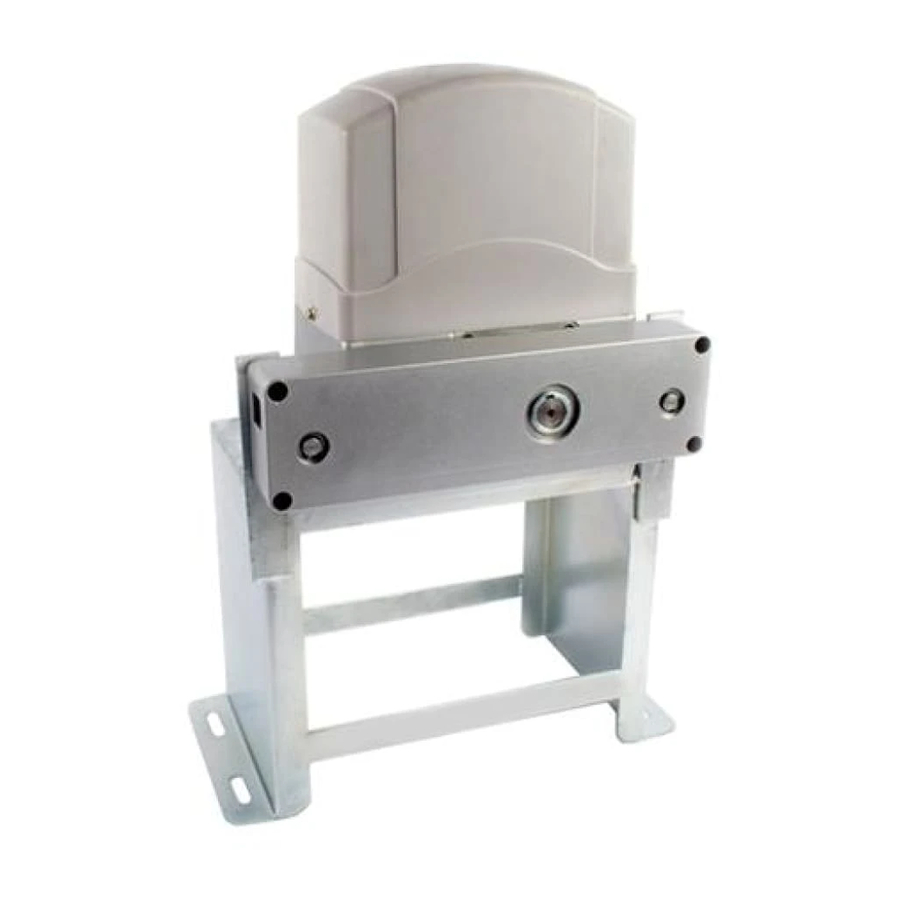
Parts List... -
Page 8: Optional Accessories Part List
Optional Accessories Parts List Technical Specifications & Features Specifications ·Power supply: 120V/60HZ or 230V/50HZ ·Motor: 120VAC or 230VAC ·Absorbed power: SCG18H:370W / SCG21H:550W ·Gate moving speed: (7.9“/second) 20 cm/second ·Max gate weight: SCG18H: 800KGS / SCG21H: 1200KGS ·Max torque: SCG18H: 24Nm / SCG21H: 35Nm ·Environmental conditions: From -15°C to +40°C ·Protection class: IP44 ·Dimensions: 29×22×27.6 CM... -
Page 9: Installation Overview
·Get the desired chain tension by adjusting the chain bolts. ·Reliable rolling code technology ·Emergency release key in case of power failure ·Stop/Reverse in case of obstruction during gate opening/closing ·Built in adjustable auto-close (0, 30, 60, 90 seconds) ·Built in max. 90 seconds Motor running time (MRT) for multiple safety protection ·Reliable electromagnetism limit for easy adjustment ·Can be equipped with wide range accessories Installation Overview... -
Page 10: Manual Operation
necessary to protect the system from flooding, heavy snow etc. 2. Prepare one or more conduits for the electrical cables before pour concrete. Remember that cable conduits have to pass through the hole in the base plate. 3. Pour concrete and before it starts to harden, check that it is parallel to the gate leaf and perfectly level. -
Page 11: Installation Of Chain And Chain Brackets
Installation of chain and chain brackets 1. Chain Brackets 1). Please refer to below chain brackets figure, which shows “U” bolt, “L” bracket and chain bolt. Use the “U” bolts (square or round) to attach the chain brackets to gate frame. 2). -
Page 12: Installation Of The Limit Switch
3. Check position of operator and chain brackets 1). The chain brackets must be mounted to the same height as the chain on the idler wheels. 2). The operator must be parallel to the gate. 3). Make sure there is 1” distance at least between the chain box and the gate after you position the base plate. -
Page 13: Connecting Of The Control Board
Connecting of the Control Board 1. Motor The BLACK wire of the motor should be connected into the “6” terminal. The RED wire of the motor should be connected into the “7” terminal. The YELLOW wire of the motor should be connected into the “8” terminal. 2. -
Page 15: Setting Of The Control Board
7. Loop Detector First insert the LOOP DETECTOR BOARD into the CONTROL BOARD, and then connect the twisted-pair to the “17” and “18” terminals. 8. External Receiver The BROWN wire of the external receiver should be connected into the “16” terminal. The BLACK wire of the external receiver should be connected into the “13”... -
Page 16: Test The Reversing Sensitivity
2. Potentiometers The potentiometer A is to adjust the OPEN stall force of the gate operator. The Potentiometer B is used to adjust the CLOSE stall force of the gate operator. Turn the potentiometer clockwise to increase the stall force. Turn the potentiometer counter-clockwise to decrease the stall force. -
Page 17: How To Learn Or Erase The Remote
How to learn or erase the remote Learn the remote Press and release the learn button, the REM LED light will be on, then press the key in the remote twice in 2 seconds, the REM LED light will flash for 4 seconds. Now the remote has been learnt successfully. -
Page 18: Maintenance
gate will stop in mid-travel or reverse before reaching the fully limit position. a. The opening force or closing force is adjusted too small. Turn the Potentiometer 1 and 2 to increase the force. b. Gate is obstructed. Remove the obstruction. 5. - Page 19 7106 S 220th St, Kent WA 98032 USA sales@WholesaleGateOpener.com ©2010-2012 LockMaster All Rights Reserved...
Need help?
Do you have a question about the SCG 18H and is the answer not in the manual?
Questions and answers