Table of Contents
Advertisement
Quick Links
Advertisement
Table of Contents

Related Manuals for LockMaster SCG 50H


Summary of Contents for LockMaster SCG 50H
- Page 1 www.WholesaleGateOpener.com...
-
Page 2: Table Of Contents
Table of Contents General Safety ……………………………………..……………………………………..………………….. 2 Preparation for Installation ……………………………………………..…………………………………..…….. 3 Parts List ………………………………………..….…………………………………..…………………………. 4 Optional Accessories Part List ………………………………………..….…………………………………..… 5 Technical Specifications & Feature …………………….……………………..…………………………………..5 Installation Overview ……………………………….…………..…………………………………..……………. 6 Installation of the Opener ……………………………………..…………………………………....……….6 Manual Operation …………………………………………..…………………………………..……………….. 7 Installation of chain and chain brackets ………………………………………..………………………………... -
Page 3: General Safety
Thank you for purchasing SCG-50H sliding gate opener. We are sure that the products will be greatly satisfying as soon as you start to use it. The product is supplied with a user’s manual which encloses installation and safety precautions. These should be read carefully before installation and operation as they provide important information about safety, installation, operation and maintenance. -
Page 4: Preparation For Installation
• Do not allow persons or children to remain in the automation operation area. • Keep radio control or other control devices out of children’s reach, in order to avoid unintentional automation activation. • The user must avoid any attempt to carry out work or repair on the automation system, and always request the assistance of qualified personnel. -
Page 5: Parts List
Parts List... -
Page 6: Optional Accessories Part List
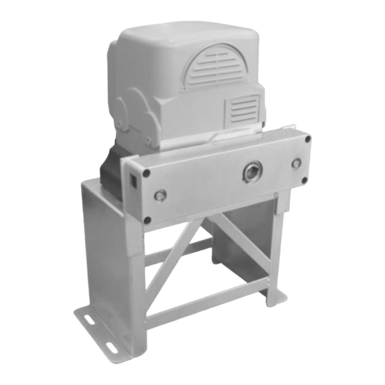
Optional Accessories Parts List Technical Specifications & Features Specifications ·Power supply: 120V/60HZ or 230V/50HZ ·Motor: 120VAC or 230VAC ·Absorbed power: 750W ·Gate moving speed: (7.9“/second) 20 cm/second ·Max gate weight: 2,600KGS ·Max torque: 75Nm ·Environmental conditions: From -15°C to +40°C ·Protection class: IP44 ·Dimensions: 40×23×55 CM Features:... -
Page 7: Installation Overview
·Get the desired chain tension by adjusting the chain bolts. ·Reliable rolling code technology ·Emergency release key in case of power failure ·Stop/Reverse in case of obstruction during gate opening/closing ·Built in adjustable auto-close (0, 30, 60, 90 seconds) ·Built in max. 90 seconds Motor running time (MRT) for multiple safety protection ·Reliable electromagnetism limit for easy adjustment ·Can be equipped with wide range accessories Installation Overview... -
Page 8: Manual Operation
The installation proceeds are as follows: 1.Dig a hole for a concrete pad which should be approximately 60 x 36 x 35cm (24〞x 14〞x 14〞). It may protrude 10 cm (4”) above ground and 25 cm (10”) in depth underground. Increase the pad height if necessary to protect the system from flooding, heavy snow etc. -
Page 9: Installation Of Chain And Chain Brackets
Installation of chain and chain brackets 1. Chain Brackets 1). Please refer to below chain brackets figure, which shows “U” bolt, “L” bracket and chain bolt. Use the “U” bolts (square or round) to attach the chain brackets to gate frame. 2). -
Page 10: Installation Of The Limit Switch
2). The opener must be parallel to the gate. 3). Make sure there is 1” distance at least between the chain box and the gate after you position the base plate. Installation of Magnets for Limit Switches Before install limit switch, make sure the gate opener is put in manual operation. (the clutch connected with gear shaft is disengaged) and the mains power supply is disconnected. -
Page 11: Connecting Of The Control Board
Connecting of the Control Board... -
Page 12: Setting Of The Control Board
1. Motor The BLACK wire of the motor should be connected into the “6” terminal. The RED wire of the motor should be connected into the “7” terminal. The YELLOW wire of the motor should be connected into the “8” terminal. 2. - Page 13 This mode enables user to drive the vehicle through the gate quickly when the gate opens to certain width. DIP Switch #1: ON – 2 Seconds OFF – 0 DIP Switch #2: ON – 4 Seconds OFF – 0 NOTE: The midway function would be disabled if both DIP switches are turned off. Factory default setting is disabled.
-
Page 14: Test The Reversing Sensitivity
Test the reversing sensitivity For the sake of safety, it is very important to test the reversing sensitivity as soon as the control board set is finished. The reversing sensitivity adjustment is inverse correlation with stall force adjustment in potentiometer A and potentiometer B. -
Page 15: Maintenance
b. The limit switches are failed. Disconnect the limit switches and try it again. c. Connecting wires or terminal blocks are too loose. Check the connecting wires and terminal blocks. d. The motor has been damaged. Replace the motor if necessary. e. - Page 16 7106 S 220th St, Kent WA 98032 USA sales@WholesaleGateOpener.com ©2010-2012 LockMaster All Rights Reserved...
Need help?
Do you have a question about the SCG 50H and is the answer not in the manual?
Questions and answers