Napoleon Tureen GD82NT-T Installation And Operation Instructions Manual
Hide thumbs
Also See for Tureen GD82NT-T:
- Installation and operation instructions manual (31 pages) ,
- Installation and operating instructions manual (56 pages) ,
- Installation and operation instructions manual (32 pages)
Table of Contents
Advertisement
Quick Links
Advertisement
Table of Contents

Related Manuals for Napoleon Tureen GD82NT-T


Summary of Contents for Napoleon Tureen GD82NT-T
- Page 1 W415-0666 / 01.28.08 $10.00 W415-0666 / 01.28.08...
-
Page 2: Table Of Contents
TABLE of CONTENTS Control Panel Removal PG 2-5 INTRODUCTION Glass/Door Replacement Warranty Bowl and Burner Removal Fireplace Dimensions Blower Replacement Installation Overview Decorative Panel Removal General Instructions Battery Replacement General Information Night Light Replacement Care of Glass 22-23 OPERATION 6-11 VENTING General Transmitter Layout Vent lengths... - Page 3 Labour related to warranty repair is covered free of charge during the first year. Repair work, however, requires the prior approval of an authorized company official. Labour costs to the account of NAPOLEON® are based on a predetermined rate schedule and any repair work must be done through an authorized NAPOLEON® dealer.
-
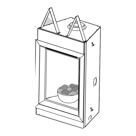
Page 4: Fireplace Dimensions
FIREPLACE DIMENSIONS FIGURE 1 58" 46" " " 4" DIA. 7" DIA. " 21" 5" " 2" " " 14" 24" GAS INLET 28" 28" INSTALLATION OVERVIEW FIGURE 2 W415-0666 / 01.28.08... -
Page 5: General Instructions
The glass is 3/16” ceramic glass available from testing of that system at test pressures in excess of 1/2 psig (3.5 your Napoleon® / Wolf Steel Ltd. dealer. Do not substitute kPa). The fireplace must be isolated from the gas supply piping materials. -
Page 6: Venting
MAXIMUM 10 FOOT VENT LENGTH CAN BE USED WITH GD201 PERISCOPE KIT When using Napoleon® venting components, use only approved HORIZONTAL VENT SECTIONS: A minimum clearance of 2” all around Wolf Steel Ltd. rigid / flexible vent components with the following the vent pipe on all horizontal runs to combustibles is required. -
Page 7: Horizontal Termination
ELBOW VENT LENGTH VALUES DEFINITIONS for the following symbols used in the venting calculations Feet Inches and examples are: 1° 0.03 > - greater than 15° 0.45 > - equal to or greater than 30° 11.0 < - less than 45°... - Page 8 HORIZONTAL TERMINATION = 6 ft when (H ) > (V = 3 ft Simple venting confi guration (only one 90° elbow) = 5 ft = 3 + 5 = 8 ft = .03 (two 90° elbows - 90°) = .03(180° - 90°) = 2.7 FIGURE 7 = 8 + 2.7 = 10.7 ft See graph to determine the required verti-...
-
Page 9: Vertical Termination
VERTICAL TERMINATION when (H ) < (V Example 4: FIGURE 10 FIGURE 11 90° 90° 90° 90° See graph to determine the required vertical rise V for the required horizontal run H REQUIRED VERTICAL RISE IN FEET = 5 ft = 6 ft = 10 ft = 5 + 6 + 10 = 21 ft... - Page 10 VERTICAL TERMINATION when (H ) > (V FIGURE 12 90° 90° 90° 90° FIGURE 13 Example 5: = 2 ft = 1 ft Simple venting confi gurations = 1.5 ft See graph to determine the required vertical rise V for the = 2 + 1 + 1.5 = 4.5 ft required horizontal run H = 6 ft...
-
Page 11: Minimum Air Terminal Location Clearances
MINIMUM AIR TERMINAL LOCATION CLEARANCES FIGURE 14 GD-301 W415-0666 / 01.28.08... -
Page 12: Installation
” ” As an alternative to framing, the vent pipe can be enclosed in the vent pipe and any wall using Napoleon® vent sleeve VS47KT. combustible material. Try to center the vent pipe FIRESTOP NOTE: THE FIRESTOP ASSEMBLY MUST BE INSTALLED... -
Page 13: Using Flexible Vent Components
USING FLEXIBLE VENT COMPONENTS For safe and proper operation of the fireplace, follow the venting FIGURE 19 WARNING instructions exactly. ELBOW All inner exhaust and outer intake vent pipe joists may be sealed Do not allow the inside vent pipe to using either red RTV high temp silicone sealant or black high bunch up on horizontal or vertical runs temp Mill Pac with the exception of the fireplace exhaust flue... -
Page 14: Extended Horizontal Air Terminal Installation
7. Aligning the seams of the terminal and air terminal connector, FIREPLACE VENT CONNECTION place the terminal over the FIGURE 22c air terminal connector 1. Install the 4” diameter flexible vent pipe to the fireplace. making sure the liner goes Secure with 3 screws into the hole in the terminal. -
Page 15: Mobile Home Installation
Use 2x4’s and frame to local building codes. Gas (NG) and Propane (LP).To convert from one gas to another NOTE: In order to avoid the possibility of exposed insulation or consult your Napoleon dealer/distributor. vapour barrier coming in contact with the fireplace body, it is GAS INSTALLATION recommended that the walls of the fireplace enclosure be “finished”... - Page 16 1" " 44" 10" 29" 1" FIGURE 30a-b WARNING Do not build into this area - it must be left clear to provide adequate clearance for the vent in this 14” wide area centered along FIGURE 31 the front of the fireplace. No combustibles are allowed.
-
Page 17: Minimum Enclosure Clearances
HORIZONTAL VENT SECTIONS: A minimum clearance of 2” all around MINIMUM ENCLOSURE CLEARANCES the vent pipe on all horizontal runs to combustibles is required. Use Minimum clearance to combustible construction from fi replace fi restop spacer W010-1799 (supplied). and vent surfaces: VERTICAL VENT SECTIONS: A minimum of 1”... -
Page 18: Minimum Mantel And Enclosure Clearances
MINIMUM MANTEL AND ENCLOSURE CLEARANCES Combustible mantel clearance can vary according to the mantel depth. Use the graph to help evaluate the clearance needed. COMBUSTIBLE NON-COMBUSTIBLE FIGURES 33 COMBUSTIBLE BRICK 0” IF NON- COMBUSTIBLE 8” MANTEL FINISHING IS NON-COMBUSTIBLE 2” USED SUCH AS 6”... -
Page 19: Finishing
FINISHING DOOR REMOVAL FIGURE 38 Before the glass door can be removed, the optional front must be removed. The glass door is secured to the top front edge of the fi rebox. Pull the handles of the latches forward, then lift the hooks out from the slots in the door frame to release the top of the door. -
Page 20: Servicing / Replacements
SERVICING / REPLACEMENTS OPTIONAL FRONT REMOVAL BOWL AND BURNER REMOVAL Remove the 6 screws that secure the burner base. Once the gas has 1a. Rectangular Front Removal been disconnected, the burner train assembly will lift out. (Fig. 38) Pull on the top of the optional front away from the fi replace until the Start by sliding the bowl forward until it clears the burner then lift from male portion of the latch disengages. -
Page 21: Decorative Panel Removal
DECORATIVE PANEL REMOVAL NIGHT LIGHT REPLACEMENT Yo u r comes equipped with our Night Light . The light has FIGURE 46 been pre-wired and is controlled from the remote control. If in the event the lamp or lens needs to be replaced, follow the instructions below. -
Page 22: Operation
OPERATION GENERAL TRANSMITTER LAYOUT FIGURE 53 FIGURE 54 ROOM THERMOSTAT FIGURE 50 The remote control can operate as a room thermostat. The thermostat can be set to a desired temperature to control the comfort level in the room. FIREPLACE OPERATION FIGURE 55 1. -
Page 23: Fan Speed
FIGURE 57 FIGURE 58 FIGURE 64 FIGURE 65 Flame OFF Flame at level 1 LOW BATTERY / MANUAL BYPASS The life span of the remote batteries depends on various factors: qual- ity of the batteries, the number of ignitions, the number of changes to the room thermostat set point, etc. -
Page 24: Operating Instructions
OPERATING INSTRUCTIONS When lit for the first time, the fireplace will emit a slight odour for a slight odour for a few hours. This is caused by dust particles in few hours. This is a normal temporary condition caused by the the heat exchanger burning off. -
Page 25: Adjustments
If ignition takes longer, consult obstructed. ® your Napoleon dealer / distributor. 1. In order to properly clean the burner and pilot assembly, remove 7. Check that the gasketing on the sides, top and bottom of the door the rocks and bowl to expose both assemblies. -
Page 26: Replacements
ERIAL UMBER OF FIREPLACE of replacement parts. Normally all parts can be ordered through your 2. I NSTALLATION DATE OF FIREPLACE Napoleon® dealer or distributor. 3. P UMBER When ordering replacement parts always give the following infor- 4. D ESCRIPTION OF PART mation: 5. - Page 27 W415-0666 / 01.28.08...
-
Page 28: Trouble Shooting Guide
TROUBLE SHOOTING GUIDE EFORE ATTEMPTING TO TROUBLESHOOT PURGE YOUR UNIT AND INITIALLY LIGHT THE PILOT AND THE MAIN BURNER WITH THE GLASS DOOR OPEN SYMPTOM PROBLEM TEST SOLUTION Main burner fl ame Blockage in vent. - remove blockage. In really cold conditions, ice buildup may occur on is a blue, lazy, the terminal and should be removed as required. - Page 29 SYMPTOM PROBLEM TEST SOLUTION - connect a jumper wire across the wall switch terminals; if main burner lights, Themostat or switch is defec- Pilot burning; no gas replace switch / thermostat. tive. to main burner; gas Wall switch wiring is defective. knob is on ‘HI’;...
- Page 30 W415-0666 / 01.28.08...
- Page 31 NOTES W415-0666 / 01.28.08...
- Page 32 NOTES W415-0666 / 01.28.08...
Need help?
Do you have a question about the Tureen GD82NT-T and is the answer not in the manual?
Questions and answers