Napoleon GD82NT-T Installation And Operating Instructions Manual
Vented natural and propane gas fireplace heaters
Hide thumbs
Also See for GD82NT-T:
- Installation and operation instructions manual (31 pages) ,
- Installation and operation instructions manual (32 pages) ,
- Installation and operation instructions manual (32 pages)
Table of Contents
Advertisement
INSTALLER: LEAVE THIS MANUAL WITH THE APPLIANCE.
CONSUMER: RETAIN THIS MANUAL FOR FUTURE REFERENCE.
CERTIFIED UNDER CANADIAN AND AMERICAN NATIONAL STANDARDS: CSA 2.33, ANSI Z21.88 FOR VENTED GAS FIREPLACE HEATERS.
CERTIFIED FOR CANADA AND UNITED STATES USING ANSI/CSA METHODS.
SAFETY INFORMATION
WARNING
!
If the information in these instructions
are not followed exactly, a fi re or
explosion may result causing property
damage, personal injury or loss of life.
- Do not store or use gasoline or other fl ammable
vapors and liquids in the vicinity of this or any
other appliance.
- WHAT TO DO IF YOU SMELL GAS:
•
Do not try to light any appliance.
•
Do not touch any electrical switch; do not use
any phone in your building.
•
Immediately call your gas supplier from a
neighbour's phone. Follow the gas supplier's
instructions.
•
If you cannot reach your gas supplier, call the
fi re department.
- Installation and service must be performed by a
qualifi ed installer, service agency or the supplier.
This appliance may be installed as an OEM
installation in manufactured home (USA only) or
mobile home and must be installed in accordance
with the manufacturer's instructions and the
Manufactured Home Construction and Safety
Standard, Title 24 CFR, Part 3280, in the United
States or the Standard for Installation in Mobile
Homes, CAN/CSA Z240 MH, in Canada.
This appliance is only for use with the type(s) of
gas indicated on the rating plate. A conversion kit
is supplied with the appliance.
Phone (705)721-1212 • Fax (705)722-6031 • www.napoleonfi replaces.com • ask@napoleonproducts.com
$10.00
OPERATING INSTRUCTIONS
Wolf Steel Ltd., 24 Napoleon Rd., Barrie, ON, L4M 4Y8 Canada /
103 Miller Drive, Crittenden, Kentucky, USA, 41030
INSTALLATION AND
GD82NT-T
NATURAL GAS
GD82PT-T
WARNING
!
PROPANE
HOT GLASS WILL CAUSE
BURNS.
DO NOT TOUCH GLASS UNTIL
COOLED.
NEVER ALLOW CHILDREN TO
TOUCH GLASS.
1.28A
W415-0769 / A / 12.10.10
1
Advertisement
Table of Contents

Related Manuals for Napoleon GD82NT-T


Summary of Contents for Napoleon GD82NT-T
-
Page 1: Safety Information
CONSUMER: RETAIN THIS MANUAL FOR FUTURE REFERENCE. INSTALLATION AND OPERATING INSTRUCTIONS CERTIFIED UNDER CANADIAN AND AMERICAN NATIONAL STANDARDS: CSA 2.33, ANSI Z21.88 FOR VENTED GAS FIREPLACE HEATERS. GD82NT-T CERTIFIED FOR CANADA AND UNITED STATES USING ANSI/CSA METHODS. SAFETY INFORMATION NATURAL GAS... -
Page 2: Table Of Contents
TABLE OF CONTENTS INSTALLATION OVERVIEW INTRODUCTION DIMENSIONS GENERAL INSTRUCTIONS GENERAL INFORMATION RATING PLATE INFORMATION VENTING VENTING LENGTHS AND COMPONENTS TYPICAL VENT INSTALLATION SPECIAL VENT INSTALLATIONS 3.3.1 PERISCOPE TERMINATION MINIMUM AIR TERMINAL LOCATION CLEARANCES VENTING APPLICATION FLOW CHART DEFINITIONS ELBOW VENT LENGTH VALUES HORIZONTAL TERMINATION VERTICAL TERMINATION INSTALLATION... -
Page 3: Installation Overview
1.0 INSTALLATION OVERVIEW See the section “FRAMING” for See the section Non-combustible “MINIMUM MANTEL See the section material AND ENCLOSURE “VENTING” and CLEARANCES” “INSTALLATION” See the section “FRAMING” and “MINIMUM MANTEL AND ENCLOSURE CLEARANCES” for Drywall (or See the section other combustible “FRAMING”... -
Page 4: Introduction
2.0 INTRODUCTION WARNING • THIS APPLIANCE IS HOT WHEN OPERATED AND CAN CAUSE SEVERE BURNS IF CONTACTED. • ANY CHANGES TO THIS APPLIANCE OR IT’S CONTROLS CAN BE DANGEROUS AND IS PROHIBITED. • Do not operate appliance before reading and understanding operating instructions. Failure to operate appliance according to operating instructions could cause fi... -
Page 5: Dimensions
DIMENSIONS 58" 46" " " 4" DIA. 7" DIA. " 21" 5" " 2" " " 14" 24" GAS INLET 28" 28" GENERAL INSTRUCTIONS WARNING ALWAYS LIGHT THE PILOT WHETHER FOR THE FIRST TIME OR IF THE GAS SUPPLY HAS RAN OUT, WITH THE GLASS DOOR OPENED OR REMOVED. - Page 6 The installation must conform with local codes or, in We suggest that our gas absence of local codes, the National Gas and Propane hearth products be installed Installation Code CSA B149.1 in Canada, or the National and serviced by professionals Fuel Gas Code, ANSI Z223.1 / NFPA 54 in the United States.
-
Page 7: General Information
CAS OU CETTE NORME D'ETATS-UNIS NE PEUT ETRE APPLIQUEE, SE REFERER A LA NORME RELATIVE AU CRITERE DE MESURES DE SECURITE CONTRE L'INCENDIEPOUR LES INSTALLATIONS DANS LES MAISONS MANUFACTURES, LES SITES ET LES COMMUNAUTES, ANSI/NFPA 501A. ECURITE CONTRE L'INCENDIEPOUR LES INSTALLATIONS DANS LES MAISONS MANUFACTURES, LES CURITE CONTRE L'INCENDIEPOUR LES INSTALLATIONS DANS LES MAISONS MANUFACTURES, LE NATURAL PROPANE PROPANE PROPA CDV82NT GD82NT-T CDV82NT-T GD82PT-T GD82PT-T GD82 CDV82PT CDV82PT CDV82PT... -
Page 8: Venting
3.0 VENTING WARNING RISK OF FIRE, MAINTAIN SPECIFIED AIR SPACE CLEARANCES TO VENT PIPE AND APPLIANCE. IF VENTING IS INCLUDED WITH SPACERS THE VENT SYSTEM MUST BE SUPPORTED EVERY 3 FEET FOR BOTH VERTICAL AND HORIZONTAL RUNS. USE SUPPORTS OR EQUIVALENT NON-COMBUSTIBLE STRAPPING TO MAINTAIN THE REQUIRED CLEARANCE FROM COMBUSTIBLES. -
Page 9: Venting Lengths And Components
VENTING LENGTHS AND COMPONENTS Use only Wolf Steel, Simpson Dura-Vent, Selkirk Direct Temp, American Metal Amerivent or Metal-Fab venting components. Minimum and maximum vent lengths, for both horizontal and vertical installations, and air terminal locations for either system are set out in this manual and must be adhered to. For Simpson Dura-Vent, Selkirk Direct Temp, American Metal Amerivent and Metal-Fab follow the installation procedure provided with the venting components. -
Page 10: Typical Vent Installation
TYPICAL VENT INSTALLATION WARNING THE FIRST 2 FEET OF OUTER 7 “ DIAMETER VENT PIPE FROM THE APPLIANCE MUST BE WRAPPED IN THE 1” THICK INSULATION SLEEVE (SUPPLIED). MAKE SURE THE INSULATION IS PULLED DOWN TIGHT TO THE APPLIANCE WHEN INSTALLED. THERE AFTER, A 2” CLEARANCE ALL AROUND THE VENT PIPE FROM COMBUSTIBLE MATERIALS ON ALL HORIZONTAL VENT SECTIONS IS REQUIRED. -
Page 11: Special Vent Installations
SPECIAL VENT INSTALLATIONS 3.3.1 PERISCOPE TERMINATION WARNING THE FIRST 2 FEET OF OUTER 7 “ DIAMETER VENT PIPE FROM THE APPLIANCE MUST BE WRAPPED IN THE 1” THICK INSULATION SLEEVE (SUPPLIED). MAKE SURE THE INSULATION IS PULLED DOWN TIGHT TO THE APPLIANCE WHEN INSTALLED. THERE AFTER, A 2” CLEARANCE ALL AROUND THE VENT PIPE FROM COMBUSTIBLE MATERIALS ON ALL HORIZONTAL VENT SECTIONS IS REQUIRED. -
Page 12: Minimum Air Terminal Location Clearances
MINIMUM AIR TERMINAL LOCATION CLEARANCES COVERED BALCONY APPLICATIONS = 3 feet = 2 x ACTUAL feet INSTALLATIONS CANADA U.S.A. 12” 12” Clearance above grade, veranda porch, deck or balcony. 12” 9” Clearance to windows or doors that open. Δ Δ 12”... -
Page 13: Venting Application Flow Chart
VENTING APPLICATION FLOW CHART TOP EXIT Horizontal Termination Vertical Termination Vertical rise is equal Vertical rise is equal Vertical rise is less Vertical rise is less to or greater than to or greater than than horizontal run than horizontal run the horizontal run the horizontal run Horizontal run +... -
Page 14: Horizontal Termination
HORIZONTAL TERMINATION ) < (V See graph to determine the required vertical Simple venting confi guration (only one 90° elbow) rise V for the required horizontal run H REQUIRED VERTICAL RISE IN FEET V 12.5 17.5 HORIZONTAL VENT RUN PLUS OFFSET IN FEET H The shaded area within the lines represents acceptable values for H... - Page 15 ) > (V Simple venting configuration (only one 90° elbow) See graph to determine the required vertical rise V for the required horizontal run H 147” REQUIRED VERTICAL RISE IN INCHES V 57” 19 1/2” 2’ 19.5’ 12.5’ HORIZONTAL VENT RUN PLUS OFFSET IN FEET H The shaded area within the lines represents acceptable values for H and V...
-
Page 16: Vertical Termination
VERTICAL TERMINATION ) < (V Simple venting configurations. See graph to determine the required vertical rise V for the required horizontal run H REQUIRED VERTICAL RISE IN FEET V HORIZONTAL VENT RUN PLUS OFFSET IN FEET H The shaded area within the lines represents acceptable values for H and V For vent configurations requiring one or more 90°... - Page 17 ) > (V Simple venting configurations. See graph to determine the required vertical rise V for the required horizontal run H REQUIRED VERTICAL RISE IN FEET V HORIZONTAL VENT RUN PLUS OFFSET IN FEET H The shaded area within the lines represents acceptable values for H and V For vent configurations requiring more than two 90°...
-
Page 18: Installation
4.0 INSTALLATION WARNING FOR SAFE AND PROPER OPERATION OF THE APPLIANCE, FOLLOW THE VENTING INSTRUCTIONS EXACTLY. ALL INNER EXHAUST AND OUTER INTAKE VENT PIPE JOINTS MAY BE SEALED USING EITHER RED RTV HIGH TEMP SILICONE SEALANT W573-0002 (NOT SUPPLIED) OR BLACK HIGH TEMP MILL PAC W573-0007 (NOT SUPPLIED) WITH THE EXCEPTION OF THE APPLIANCE EXHAUST FLUE COLLAR WHICH MUST BE SEALED USING MILL PAC. -
Page 19: Horizontal Installation
4.1.1 HORIZONTAL INSTALLATION WARNING THE FIRESTOP ASSEMBLY MUST BE INSTALLED WITH THE VENT SHIELD TO THE TOP. TERMINALS MUST NOT BE RECESSED INTO A WALL OR SIDING MORE THAN THE DEPTH OF THE RETURN FLANGE OF THE MOUNTING PLATE. This application occurs when venting through an exterior wall. Having determined the correct height for the air terminal VENT location, cut and frame a hole in the exterior wall as... -
Page 20: Using Flexible Venting Components
USING FLEXIBLE VENTING COMPONENTS WARNING DO NOT ALLOW THE INNER FLEX PIPE TO BUNCH UP ON HORIZONTAL OR VERTICAL RUNS AND ELBOWS. KEEP IT PULLED TIGHT. SPACERS ARE ATTACHED TO THE INNER FLEX PIPE AT PREDETERMINED INTERVALS TO MAINTAIN AN EVEN AIR GAP TO THE OUTER FLEX PIPE. -
Page 21: Vertical Air Terminal Installation
4.2.2 VERTICAL AIR TERMINAL INSTALLATION WARNING MAINTAIN A MINIMUM 2” SPACE BETWEEN THE AIR INLET BASE AND THE STORM COLLAR. Fasten the roof support to the roof using the screws provided. The roof support is optional. In this case the venting is to be adequately supported using either an alternate method suitable to the authority having jurisdiction or the optional roof support. -
Page 22: Appliance Vent Connection
4.2.3 APPLIANCE VENT CONNECTION Install the inner fl ex pipe to the appliance. Secure with 3 screws #8 X 1/2” and fl at washers. Seal the joint and screw holes using the high SELF temperature sealant W573-0007 (not supplied). DRILLING SCREWS Install the outer fl... -
Page 23: Vertical Air Terminal Installation
4.3.3 VERTICAL AIR TERMINAL INSTALLATION Move the appliance into position. INNER PIPE Fasten the roof support to the roof using the screws provided. The roof support is optional. In this case the venting is to be adequately supported using either an alternate method suitable to the authority having jurisdiction or the optional roof support. -
Page 24: Gas Installation
GAS INSTALLATION WARNING RISK OF FIRE, EXPLOSION OR ASPHYXIATION. ENSURE THERE ARE NO IGNITION SOURCES SUCH AS SPARKS OR OPEN FLAMES. SUPPORT GAS CONTROL WHEN ATTACHING GAS SUPPLY PIPE TO PREVENT DAMAGING GAS LINE. ALWAYS LIGHT THE PILOT WHETHER FOR THE FIRST TIME OR IF THE GAS SUPPLY HAS RUN OUT WITH THE GLASS DOOR OPENED OR REMOVED. -
Page 25: Mobile Home Installation
MOBILE HOME INSTALLATION This appliance is certifi ed to be installed as an OEM (Original Equipment Manufacturer) installation in a manufactured home or mobile home and must be installed in accordance with the manufacturer’s instructions and the Manufactured Home Construction and Safety Standard, Title 24 CFR, Part 3280, in the United States or the Mobile Home Standard, CAN/CSA Z240 MH Series, in Canada. -
Page 26: Framing
5.0 FRAMING WARNING RISK OF FIRE! IN ORDER TO AVOID THE POSSIBILITY OF EXPOSED INSULATION OR VAPOUR BARRIER COMING IN CONTACT WITH THE APPLIANCE BODY, IT IS RECOMMENDED THAT THE WALLS OF THE APPLIANCE ENCLOSURE BE “FINISHED” (IE: DRYWALL / SHEETROCK), AS YOU WOULD FINISH ANY OTHER OUTSIDE WALL OF A HOME. - Page 27 WARNING Do not build into this area - it must be left clear to provide adequate clearance for the vent in this 14” wide area centered along the front of the fireplace. No combustibles are allowed. Fireplace should be in its final location before framing.
-
Page 28: Minimum Clearance To Combustibles
MINIMUM CLEARANCE TO COMBUSTIBLES Maintain these minimum clearances to combustibles from appliance and vent surfaces Non-combustible appliance fi nishing: - 4” from the sides of the appliance opening - 22 3/8” to the top of the appliance opening Combustible appliance fi nishing: - 0”... -
Page 29: Minimum Clearance To Combustible Enclosures
MINIMUM CLEARANCE TO COMBUSTIBLE ENCLOSURES WARNING RISK OF FIRE! THE FRONT OF THE APPLIANCE MUST BE FINISHED WITH ANY NON-COMBUSTIBLE MATERIALS SUCH AS BRICK, MARBLE, GRANITE, ETC., AS LONG AS THE FINISHING MATERIAL DOES NOT GO BELOW THE SPECIFIED DIMENSION AS ILLUSTRATED. AS AN ALTERNATIVE, YOU CAN FINISH THE APPLIANCE WITH DRYWALL, SEE DIAGRAM BELOW FOR DETAILS. - Page 30 COMBUSTIBLE MATERIAL WARNING Finishing must be done using a non- combustible material placed flush with the front face of the unit and extending from the top of the unit such as cement board, ceramic tile, marble, etc. DO NOT USE WOOD OR DRYWALL. Any firerated drywall is not acceptable.
-
Page 31: Minimum Mantel Clearances
MINIMUM MANTEL CLEARANCES WARNING RISK OF FIRE, MAINTAIN ALL SPECIFIED AIR SPACE CLEARANCES TO COMBUSTIBLES. FAILURE TO COMPLY WITH THESE INSTRUCTIONS MAY CAUSE A FIRE OR CAUSE THE APPLIANCE TO OVERHEAT. ENSURE ALL CLEARANCES (I.E. BACK, SIDE, TOP, VENT, MANTEL, FRONT, ETC.) ARE CLEARLY MAINTAINED. -
Page 32: Finishing
6.0 FINISHING WARNING RISK OF FIRE! NEVER OBSTRUCT THE FRONT OPENING OF THE APPLIANCE. THE FRONT OF THE APPLIANCE MUST BE FINISHED WITH ANY NON-COMBUSTIBLE MATERIALS SUCH AS BRICK, MARBLE, GRANITE, ETC., PROVIDED THAT THESE MATERIALS DO NOT GO BELOW THE SPECIFIED DIMENSION AS ILLUSTRATED. DO NOT STRIKE, SLAM OR SCRATCH GLASS. -
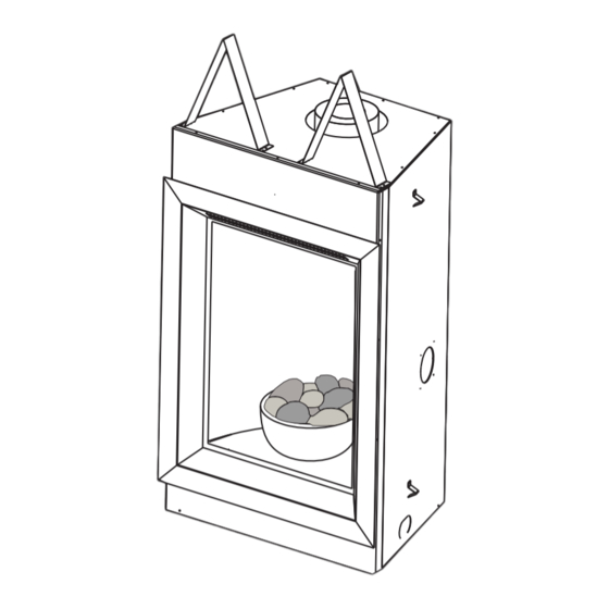
Page 33: Shipping Bracket
SHIPPING BRACKET Before installing the bowl and rocks, you must fi rst remove the shipping bracket. Lift up to remove. BOWL, MESH AND ROCK PLACEMENT SCREW W/ SPACER Carefully slide the opening in the rear of the Place the steel mesh inside the bowl making bowl over the burner making sure to line the sure there is even space between the mesh holes in the bottom of the bowl with the 2... -
Page 34: Afk82/Rfk82 Facing Kit Installation
AFK82/RFK82 FACING KIT INSTALLATION Attach screw and spacer as illustrated to the bottom and top of both sides of the front housing. Attach the two hooks as illustrated using the screws supplied. (The hooks must be installed on the inside of the bracket). These hooks will catch the front in the event the latch disengages. -
Page 35: Wiring Diagram / Electrical Information
7.0 WIRING DIAGRAM / ELECTRICAL INFORMATION ELECTRICAL CONNECTION WARNING DO NOT USE THIS APPLIANCE IF ANY PART HAS BEEN UNDER WATER. CALL A QUALIFIED SERVICE TECHNICIAN IMMEDIATELY TO HAVE THE APPLIANCE INSPECTED FOR DAMAGE TO THE ELECTRICAL CIRCUIT. RISK OF ELECTRICAL SHOCK OR EXPLOSION. DO NOT WIRE 110V TO THE VALVE OR TO THE APPLIANCE WALL SWITCH. -
Page 36: Operation
8.0 OPERATION WARNING IF YOU DO NOT FOLLOW THESE INSTRUCTIONS EXACTLY, A FIRE OR EXPLOSION MAY RESULT CAUSING PROPERTY DAMAGE, PERSONAL INJURY OR LOSS OF LIFE. ALWAYS LIGHT THE PILOT WHETHER FOR THE FIRST TIME OR IF THE GAS SUPPLY HAS RUN OUT WITH THE GLASS DOOR OPENED OR REMOVED. -
Page 37: Temperature Display
TEMPERATURE DISPLAY With the system in the “OFF” position, press the Thermostat Key and the Mode Key at the same °F °C time to change from degrees F to C. Look at the LCD screen on the Transmitter to verify that a C or F is visible to the right of the Room Temperature display. -
Page 38: Fan Speed
FAN SPEED If the appliance is equipped with a hot air circulating fan, the speed of the fan can be controlled by the remote °F °F system. The fan speed can be adjusted through six (6) speeds. Use the Mode key to guide you to the fan control icon. -
Page 39: Low Battery / Manual Bypass
8.11 LOW BATTERY / MANUAL BYPASS The life span of the remote batteries depends on various factors: quality of the °F batteries, the number of ignitions, the number of charges to the room thermostat set point, etc. When the transmitter batteries are low, a Battery Icon will appear on the LCD display before all battery power is lost. -
Page 40: Operating Instructions
9.0 OPERATING INSTRUCTIONS WARNING IF YOU DO NOT FOLLOW THESE INSTRUCTIONS EXACTLY, A FIRE OR EXPLOSION MAY RESULT CAUSING PROPERTY DAMAGE, PERSONAL INJURY OR LOSS OF LIFE. ALWAYS LIGHT THE PILOT WHETHER FOR THE FIRST TIME OR IF THE GAS SUPPLY HAS RUN OUT WITH THE GLASS DOOR OPENED OR REMOVED. -
Page 41: Adjustments
10.0 ADJUSTMENTS 10.1 RESTRICTING VERTICAL VENTS Vertical terminations may display a very active fl ame. If this appearance is not desirable, the vent exit must be restricted TOP OF FIREBOX using restrictor plate W500-0205. This reduces the velocity of the exhaust gases, slowing down the fl ame pattern and creating a more traditional appearance. -
Page 42: Venturi Adjustment
10.3 VENTURI ADJUSTMENT This appliance has an air shutter that has been factory set open according to the chart below: VENTURI BURNER Regardless of venturi orientation, closing the air shutter will cause a more yellow flame, but can lead to carboning. Opening the air shutter will cause a more blue flame, but can cause flame lifting from the burner ports. -
Page 43: Maintenance
11.0 MAINTENANCE MAINTENANCE MAINTENANCE WARNING MAINTENANCE TURN OFF THE GAS AND ELECTRICAL POWER BEFORE SERVICING THE APPLIANCE. APPLIANCE MAY BE HOT, DO NOT SERVICE UNTIL APPLIANCE HAS COOLED. DO NOT USE ABRASIVE CLEANERS. CAUTION: Label all wires prior to disconnection when servicing controls. Wiring errors can cause improper and dangerous operation. -
Page 44: Decorative Panel / Base Removal
11.2 DECORATIVE PANEL / BASE REMOVAL Insert a gloved hand behind the top right corner of the panel and pull forward gently. Place your hands along the edge of the panel allowing it to come out of its place in the fi rebox. Then pull forward slightly allowing the panel to rest on the fi... -
Page 45: Spark Module Battery Installation
11.3 SPARK MODULE BATTERY INSTALLATION Remove optional front, see “AFK82/RFK82 FACING KIT INSTALLATION” section. Tilt the control panel forward and remove BURNER allowing access to the electrode box which is screwed to the base of the fi rebox. CONTROL PANEL Pull back on the battery compartment door RECEIVER latch and remove. -
Page 46: Night Light™ Replacement
11.5 NIGHT LIGHT™ REPLACEMENT Your comes equipped with our “Night Light™”. LENSE The light has been pre-wired and is controlled from the remote FRAME control. If in the event the lamp or lens needs to be replaced, follow the SCREWS instructions below. -
Page 47: Care Of Glass
11.7 CARE OF GLASS WARNING DO NOT CLEAN GLASS WHEN HOT! DO NOT USE ABRASIVE CLEANERS TO CLEAN GLASS. HOT GLASS WILL Buff lightly with a clean dry soft cloth. Clean both sides CAUSE BURNS. of the glass after the fi rst 10 hours of operation with a DO NOT TOUCH GLASS recommended fi... -
Page 48: Replacement Parts
12.0 REPLACEMENT PARTS WARNING FAILURE TO POSITION THE PARTS IN ACCORDANCE WITH THIS MANUAL OR FAILURE TO USE ONLY PARTS SPECIFICALLY APPROVED WITH THIS APPLIANCE MAY RESULT IN PROPERTY DAMAGE OR PERSONAL INJURY. ** THIS IS A FAST ACTING THERMOCOUPLE. IT IS AN INTEGRAL SAFETY COMPONENT. REPLACE ONLY WITH A FAST ACTING THERMOCOUPLE SUPPLIED BY WOLF STEEL LTD. - Page 49 COMPONENTS REF NO. PART NO. DESCRIPTION W225-0240 DOOR W010-1500 GLASS C/W GASKET W500-0205 RESTRICTOR W660-0086 FAN CONTROL MODULE FLEXIBLE VENT KITS REF NO. PART NO. DESCRIPTION GD-220 (5 FT) W010-0397 4” FLEXIBLE VENT PIPE - (5 FT) C/W SPACERS W410-0017 7”...
- Page 50 W415-0769 / A / 12.10.10...
-
Page 51: Trouble Shooting Guide
13.0 TROUBLE SHOOTING GUIDE SYMPTOM PROBLEM TEST SOLUTION Main burner fl ame Blockage in vent. Remove blockage. In really cold conditions, ice is a blue, lazy, buildup may occur on the terminal and should be transparent fl ame. removed as required. Incorrect installation. - Page 52 SYMPTOM PROBLEM TEST SOLUTION Main burner goes Pilot fl ame is not large Turn up the pilot fl ame. out; pilot stays on. enough or not engulfi ng Replace pilot assembly. the thermopile. Thermopile shorting. Clean thermopile connection to the valve. Reconnect. Replace thermopile / valve.
- Page 53 SYMPTOM PROBLEM TEST SOLUTION Pilot goes out Gas piping is undersized. Turn on all gas appliances and see if pilot fl ame while standing: fl utters, diminishes or extinguishes, especially Main burner is in when main burner ignites. Monitor appliance supply “OFF”...
-
Page 54: Warranty
14.0 WARRANTY NAPOLEON® products are manufactured under the strict Standard of the world recognized ISO 9001 : 2008 Quality Assurance Certifi cate. NAPOLEON® products are designed with superior components and materials assembled by trained craftsmen who take great pride in their work. The burner and valve assembly are leak and test-fi red at a quality test station. The complete appliance is again thoroughly inspected by a qualifi... -
Page 55: Service History
15.0 SERVICE HISTORY 43.1 W415-0769 / A / 12.10.10... - Page 56 16.0 NOTES 44.1 W415-0769 / A / 12.10.10...
Need help?
Do you have a question about the GD82NT-T and is the answer not in the manual?
Questions and answers