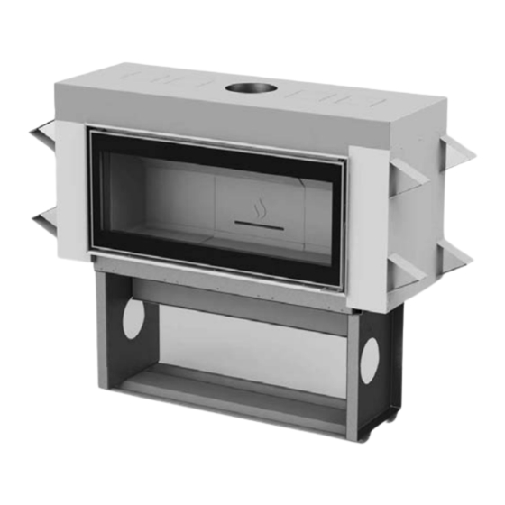
Town & Country Fireplaces TCW120 Installation And Operating Instructions Manual
Zero clearance wood
fireplace
Hide thumbs
Also See for TCW120:
- Operating instructions manual (32 pages) ,
- Operating instructions manual (32 pages) ,
- Installation and operating instructions manual (32 pages)
Table of Contents
Advertisement
Quick Links
IMPORTANT:
THESE INSTRUCTIONS ARE TO
REMAIN WITH THE HOMEOWNER.
PLEASE SAVE THESE INSTRUCTIONS.
SAFETY NOTICE
If this fireplace is not properly installed, a
house fire may result. For your safety, follow
the installation instructions. Contact local
building or fire officials about restrictions
and installation inspection requirements in
your area.
TESTED and LISTED to CAN/ULC
S610-M87 AND UL 127
Phase 2 Qualified, U.S. Environmental
Protection Agency wood-burning fireplace
program.
©PACIFIC ENERGY FIREPLACE
040215-32
PRODUCTS LTD. - 2014
INSTALLATION
AND OPERATING
INSTRUCTIONS
MODEL: TCW120
ZERO CLEARANCE WOOD
FIREPLACE
T120.BODYA
SERIAL #
5055.120
Advertisement
Table of Contents

Related Manuals for Town & Country Fireplaces TCW120


Summary of Contents for Town & Country Fireplaces TCW120
-
Page 1: Safety Notice
TESTED and LISTED to CAN/ULC S610-M87 AND UL 127 Phase 2 Qualified, U.S. Environmental Protection Agency wood-burning fireplace program. MODEL: TCW120 ZERO CLEARANCE WOOD FIREPLACE ©PACIFIC ENERGY FIREPLACE 040215-32 T120.BODYA 5055.120 PRODUCTS LTD. - 2014... -
Page 2: Table Of Contents
Contents Safety .................... 3 Creosote Formation and Need for Removal .......... 3 Chimney Fires ..................3 Avoiding a Chimney Fire ................ 3 In the event of a Chimney Fire ............... 3 Operation ..................4 NOTE: Wood Selection..................4 How to Test Your Wood ................4 WE STRONGLY Lighting for the First Time .............. -
Page 3: Safety
Safety Avoiding a Chimney Fire There are two ways to avoid chimney fires: Creosote Formation and Need for 1. Do not let creosote build up to a point where a chimney Removal fire is possible. When wood is burned slowly, it produces tar and other 2. -
Page 4: Operation
Operation Lighting for the First Time Curing of the Paint Finish/Insulation CAUTION: HOT WHILE IN OPERATION. KEEP To achieve the best finish, the paint on your fireplace CHILDREN, CLOTHING AND FURNITURE must be baked on. Burn only half the normal wood load AWAY. -
Page 5: Controlling Your Fire
Proper Draft WARNING: No alteration or modification of the combustion air assembly is permitted. Any tampering will void warranty and could be very hazardous. 1. Draft is the force which moves air from the appliance up through the chimney. The amount of draft in your WARNING: Only use the Town &... -
Page 6: Maintenance
Maintenance WARNING: OVER FIRING THE APPLIANCE WILL SHORTEN THE LIFE OF THE PRODUCT. FAILURE TO RECTIFY AN OVER FIRING CONDITION CAN BE HAZARDOUS AND MAY VOID THE MANUFACTURER'S 1. Burn only, dry and well seasoned cord wood. The WARRANTY. denser or heavier the wood when dry, the greater its heat value. -
Page 7: Maintenance Checks
Maintenance Checks Check the following parts for damage such as cracks, excessive corrosion, burned out sections and excessive warping: (See website for descriptions and more detail) Weekly: - Aluker Panels- Visual, for cracking, placement. - Door Gasket - sagging, placement, damage. Monthly - Back side of airwash chamber. -
Page 8: Aluker Panel Installation
Aluker Panel Installation This package contains 11 Aluker Panels. 1) With the fireplace in the upright position, install panels in the order shown from 1 to 11. 2) When installing panel #9, #10 & 11, secure with the Aluker support brackets as shown in Fig. -
Page 9: Aluker Panel Installation Sequence
Aluker Panel Installation Sequence: Tuck the front edge of the panel in behind the top shield, lift Place panel 1 into the bottom of the unit, tuck under the the panel and swing into place against the firebox. Lower front lip first then lay flat and slide over to your left. gently onto the bottom right panel. - Page 10 Place panel 10 onto the upper ledge of the rear right panel Place panel 7 onto the back ledge of the bottom right panel and slide over to your left and under the secondary air and slide over to your right in behind the right side panel. bracket.
-
Page 11: Fireplace Installation
Fireplace Installation Crate Removal 1) Carefully remove wood top and supports. 2) Remove the screws securing the fireplace to the pallet(4). 3) Remove from pallet bottom. Warning: Under no circumstances is this fireplace to be installed in a makeshift or "temporary" manner. It may be fired only after the following installation conditions have been met. -
Page 12: Procedure
Procedure FIG. #3 Note: See "Combustion Air" section on page 19. MAINTAIN CLEARANCES TO COMBUSTIBLES AS SPECIFIED IN THE INSTALLATION INSTRUCTIONS CAUTION: THE STRUCTURAL INTEGRITY OF THE FLOOR, WALL AND CEILING/ROOF MUST BE MAINTAINED. THE FIREPLACE MUST BE CONNECTED TO A FACTORY-BUILT CHIMNEY CONFORMING TO CAN/ ULC-S629 OR UL 103HT STANDARDS FOR 650C FACTORY-BUILT CHIMNEYS. -
Page 13: Minimum Framing Dimensions
Minimum Framing Dimensions NOTE: THE FRAMING FIG. #5 CLEARANCES AROUND THE FIREPLACE MUST 24" INCLUDE THE INNER DRY- 610mm WALL/CONCRETE BOARD AS WELL. 72" 1.83m 81" 2.06m 32" 813mm 4" 102mm 81" " 2.06m 72" 1.15m 1.83m " 2.91m 88" 2.24m 72"... -
Page 14: Minimum Clearances To Combustibles
Minimum Clearances to Combustibles 36" FIG. #7 " 914mm 64mm 4" 32" 102mm 813mm 45" 1.14m " 337mm " 140mm 4" 102mm Fireplace Clearances and Dimensions Distance of combustible material from side, back stando s and framing kit. 24” (610mm) Minimum distance of adjacent wall to side of replace door. -
Page 15: Chimney Installation
Chimney Installation Listed Chimney and Chimney Connector 7. Install the roof support then assemble flashing and storm collar and be sure to maintain the vapour barrier THE FIREPLACE MUST BE CONNECTED TO A at this point. (Seal securely.) FACTORY-BUILT CHIMNEY CONFORMING TO CAN/ ULC-S629 AND UL 103HT STANDARDS FOR 650C 8. - Page 16 The chimney may incorporate FIG. #8 Spark arrestor an offset. To do this safely, all rain cap sections of listed connector, offset elbows and chimney section must be screwed Chimney must extend a together by at least three minimum of 3' above roof. sheet metal screws per joint.
-
Page 17: Offsets
Offsets The chimney for the T120 can be installed with a maximum FIG. #9 of four 45° elbows(in Canada) or four 30° elbows(in U.S.A.) as shown in Fig. #9. Installation: 1. Install the first elbow; turn it in the required direction. It is required to secure connections with three (3) #8 x ½"... -
Page 18: Combustion Air
Combustion Air FIG. #10 Intake or combustion air can be supplied to the fireplace in one of two ways. Consult your local building code or CAN/CSA-B365, Installation Code for Solid-Fuel-Burning Appliances and Equipment before proceeding. 1. Outside air supply - Outside air may be brought in and connected to the six inch adapater underneath the unit. -
Page 19: Ember Protector
Ember Protector Safety Strip The floor between the fireplace and the hearth extension/ ember protection must be protected with a 2"(51mm) deep The stove may be installed on a combustible floor provided safety metal strip(not provided) equal to the width of the ember protection made from a non-combustible material unit. - Page 20 Board Installation The front facing area of the T120 must be finished with FIG. #15 steel stud framing and with non-combustible cement board as shown in Fig.#15 and #16 prior to applying any finishing material. The cement board can be attached to the framing and to the front of the unit.
-
Page 21: Remote Heat Duct Installation
Remote Heat Duct Installation FIG. #17 FROM OUTER EDGE 12” min OF GRILL TO ANY FLOOR, CEILING OR WALL REMOTE HEAT DUCT MAKE UP AIR INLET CONTENTS: FIG. #18 1 - REMOTE HEAT FLAP BOX 1 - JUNCTION BOX 1 - RHEOSTAT KIT 1 - OUTLET BLOWER ASSEMBLY Heat Duct 1 - HEAT DUCT ADAPTER... -
Page 22: Electrical Wiring
unit, and secure to the framing. Fig. #19 FIG. #19 4. The edge of the outlet grill must be a minimum 12” from BLOWER ASSEMBLY the floor, any adjacent wall and from the ceiling. 5. Attach the 3 1/4"(83mm) X 10"(254mm) Transition Boot to the Remote Blower Assembly and seal with aluminium duct tape. -
Page 23: Changing Door Configuration
Changing Door Configuration FIG. #21 The door on the T120 comes factory set to open to the left but may be changed if desired. To change the door opening direction follow these instructions: NOTE: The door on the T120 is heavy and should be installed or removed by two people. - Page 24 4. Attach the door catches"C" to the left side of the unit and FIG. #24 the right non-adjustable bottom hinge "B" onto the bot- tom right side of the unit. (opposite hinge brackets can be found in the hardware pack.) HINGE "A"...
-
Page 25: Troubleshooting
Appendix A Troubleshooting Problem Cause Cure Glass is Dirty 1. Wood is wet - Use dry wood 2. Draft too low - Chimney plugged or restricted, inspect and clean - Provide outside air for combustion - Improper chimney height and / or diameter 3. -
Page 26: Understanding & Operating Your Town & Country Fireplace
Understanding & Operating Your Town & Country Fireplace The Town & Country line of fireplaces is a culmination of years of research and development. Designed to be efficient, clean-burning and user-friendly, this fireplace will give you years of service. However, a knowledgeable operator is still the most important factor for maximum performance and part of this is understanding the basic functions of this design. -
Page 27: Replacement Parts
Replacement Parts ITEM DESCRIPTION PART NO. 1.... Aluker panels (set) ......T120.ALUKER 2.... Airwash deflector Assembly....TWRP.7915 3.... Ash Guard Assembly......TWRP.7916 4.... Lintel Assembly ........TWRP.7917 5.... Door Gasket ........TWRP.DGKIT 6.... Replacement Glass ....TWRP.5034MC120 7.... Door Assembly ......TWRP.5036MC120 8.... - Page 28 T120.BODYA 040215-32...
- Page 29 T120.BODYA 040215-32...
- Page 30 T120.BODYA 040215-32...
-
Page 31: Label Location
Label Location FOYER PRÉFABRIQUÉ HOMOLOGUÉ / CERTIFIÉ POUR UTILISATION AU CANADA ET AUX É.-U.TESTÉ SELON ULC S610-M87 ET UL 127-2011. ETL#4001507 TCW120 SERIES/SÉRIE: MODEL/ MODÈLE: The rating label is located beneath the • INSTALL AND USE IN ACCORDANCE WITH THE INSTALLATION AND OPERATING INSTRUCTIONS SUPPLIED WITH THE firebox on the casing floor and can be APPLIANCE. - Page 32 PACIFIC ENERGY FIREPLACE PRODUCTS LTD. 2975 Allenby Rd., Duncan, B.C. V9L 6V8 Phone: 250-748-1184 Web site: http://www.townandcountryfireplaces.net Printed in Canada...
Need help?
Do you have a question about the TCW120 and is the answer not in the manual?
Questions and answers