Table of Contents
Advertisement
Quick Links
Advertisement
Table of Contents

Related Manuals for Dedicated Micros HyperSense


Summary of Contents for Dedicated Micros HyperSense
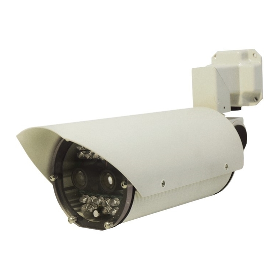
- Page 1 HyperSense ANPR Camera Installation Manual www.dedicatedmicros.com...
-
Page 2: Table Of Contents
Appendix A ...............22 Appendix B ...............24 Index ................27 Whilst every attempt is made to ensure these manuals are accurate and current, Dedicated Micros reserve the right to alter or modify the specification of the machine described herein without prejudice. Dedicated Micros ©2008... -
Page 3: Introduction
ANPR cameras. By providing images of just the vehicle number plates, HyperSense cameras are ideal for use in ANPR systems as they simplify the task of recognising number plates, allowing the analytics software to operate more accurately and efficiently. -
Page 4: Rf Interference Warning
Connect the equipment into an outlet on a different circuit different to the receiver. Consult the dealer or an experienced radio/TV technician for help. Modifications not expressly approved by the manufacturer could void the user’s authority to operate the equipment under FCC rules. Dedicated Micros ©2008... -
Page 5: Camera Care
• EN 60825-1 Safety standard for LED’s and Lasers. Further details about these applicable standards can be obtained from Dedicated Micros Ltd. 1200 Daresbury Park, Daresbury, Cheshire, WA44HS. A “Declaration of Conformity” with all relevant European Union Directives has been made, is on file and is available from the Dedicated Micros address above. -
Page 6: Components Supplied
Before installing the camera, please remove the components from the packaging and verify that all items listed below have been supplied: Components Supplied 1 x DM HyperSense ANPR Camera IP66 housing with pre-wired cabling 1 x DM HyperSense ANPR Manual 1 x 3mm A/F Allen Key... -
Page 7: Installing The Camera
If trucks are expected then this height could have to exceed 6 meters which could affect the cameras ability to capture license plates. In addition, a mounting over traffic will present problems if servicing or repair is required. Dedicated Micros ©2008... -
Page 8: Side Mounting
20 mph (32 kph). In order to control traffic speed at the entrance to the site it may be advisable to employ direction control kerbing, speed bumps or traffic flow control plates. Dedicated Micros ©2008... -
Page 9: Mounting
Use a 3mm A/F ball allen key to tighten either one or both of the grub screws against the housing in the desired orientation. Remember to loosen these grub screws before attempting to re-orientate the housing at any time in the future. Dedicated Micros ©2008... -
Page 10: Electrical Connections
• Power Cable for installer termination into appropriate 12VDC 1A/24VAC 500mA PSU NOTE: The HyperSense ANPR camera housing must be earthed by connecting the earth wire in the power cable to a suitable ground. The cables are factory fitted to simplify installation and to ensure the camera housing is watertight. -
Page 11: Adjusting Fov And Focus
Remove the 6 off M5 x 20 socket head screws from the back plate, using a 4mm A/F long series ball allen key. These screws are held captive in the housing. Slide the body and sunshield along the camera platform until it becomes engaged on the hook. Let the body and sunshield hang from the hook. Dedicated Micros ©2008... -
Page 12: Methods Of Adjusting Focus And Fov
Note: Safety is paramount. Do not stand in the road unless the road has been closed. • If the road cannot be closed or the road is busy, passing traffic can be used to configure the camera. Dedicated Micros ©2008... -
Page 13: Configuring The Unit - Intelligent Camvu Version Only
IP address e.g. setip 192.168.1.100 setsub followed by the new subnet mask e.g. setsub 255.255.0.0 setgw followed by the new gateway address e.g. setgw 192.168.50.1 reset (to reset the camera so that the new IP address settings are adopted) Dedicated Micros ©2008... -
Page 14: Accessing The Configuration Web Pages
The other configuration menus are accessible via the links on the left hand side of the page. Note: Changes made to the settings on the webpages are automatically saved to the camera when the webpage is refreshed or a different page is selected. Dedicated Micros ©2008... -
Page 15: System
The Serial Port on the camera can be used for debug ie finding the IP address, refer to Locating the unit IP address. Ramdisk (A): The camera is capable of storing data internally. This is the amount of memory allocated to ftp operation. Dedicated Micros ©2008... -
Page 16: Network Menu
DHCP is disabled once an IP address is assigned in the IP address box. Note: Always consult the network administrator for IP address, Subnet Mask and Gateway information. Dedicated Micros ©2008... -
Page 17: Anpr Menu
Similarly countries are removed from the selected list using the ‘<’ button. The list of countries can be reordered using the ‘+’ and ‘-’ buttons. The order determines the priority in which syntax checking is applied when performing a plate reading. Dedicated Micros ©2008... -
Page 18: Alarms
This is also known as pre-alarm, it allows the vehicle approach to be associated with the attempted entry. Test The button allows the configured parameters to be tested. It will send a dummy alarm to the configured servers. Dedicated Micros ©2008... -
Page 19: Connections
Connections This page shows the IP addresses of machines currently connected to the camera via the network IP Addresses A list of up to four IP addresses connected to the camera will be displayed Dedicated Micros ©2008... -
Page 20: Reset
Reset This page allows the camera to be restarted remotely. Reset System Dedicated Micros ©2008... -
Page 21: Camera Dimensions
Camera Dimensions Overall Dimensions All dimensions in millimetres Mounting Template 50.8 23.5 Dedicated Micros ©2008... -
Page 22: Appendix A
Upgrading Software To upgrade webpages Download the new files required from the Dedicated Micros website and save them in a folder on the hard drive of the PC. These can then be transferred using ftp to the camera. To ftp webpages from the DOS prompt. -
Page 23: To Upgrade Bootloader
This opens up a dos window. • Type ‘cd\’ to get to the c:\ prompt • Type ‘cd c:\hypersense (or insert the local folder holding the downloaded files). • Type ‘dir’. The zip file should be displayed. • Type ‘ftp <ipaddress>’ replacing <ipaddress> with the ip address of the unit. -
Page 24: Appendix B
Appendix B Serial pinouts The pin out configuration of the 9 pin D plug fitted to the CamVu version of the HyperSense ANPR camera is as follows; RS232 Connectivity Description Desc Data Carrier Detect Receive Data Transmit Data Data Terminal Ready... - Page 25 Notes Dedicated Micros ©2008...
- Page 26 Notes Dedicated Micros ©2008...
-
Page 27: Index
Index Accessing the Configuration Web Pages .....................14 Accessory ...............................6 Additional components for analogue HyperSense ANPR camera..............6 Additional components for analogue HyperSense ANPR with overview camera ...........6 Adjusting FOV and Focus..........................11 Alarms ................................18 Analogue ANPR Camera connections......................10 Analogue ANPR with Overview Camera connections ..................10 Analogue Camera............................10... - Page 28 Neckarstrafle 15, 14434 Albemarle Point Place, Suite 100, 41836 Hückelhoven, Germany Chantilly, Virginia 20151 USA Dedicated Micros France Dedicated Micros, Australia PTY. 9-13 rue du Moulinet 5/3 Packard Avenue, Castle Hill, 75013 Paris, France NSW 2154, Australia Dedicated Micros Slovenia...
Need help?
Do you have a question about the HyperSense and is the answer not in the manual?
Questions and answers