Table of Contents

Subscribe to Our Youtube Channel
Related Manuals for Future light COLOR WAVE


Summary of Contents for Future light COLOR WAVE
- Page 1 BEDIENUNGSANLEITUNG USER MANUAL COLOR WAVE LED moving bar © Copyright Für weiteren Gebrauch aufbewahren! Nachdruck verboten! Keep this manual for future needs! Reproduction prohibited!
-
Page 2: Table Of Contents
Inhaltsverzeichnis EINFÜHRUNG ..............................4 Lieferumfang ..............................4 SICHERHEITSHINWEISE ..........................4 BESTIMMUNGSGEMÄßE VERWENDUNG ..................... 6 GERÄTEBESCHREIBUNG ..........................7 Features ................................. 7 Geräteübersicht .............................. 8 INSTALLATION ..............................9 Projektormontage ............................9 Anschluss an den DMX-512 Controller / Verbindung Projektor – Projektor ..........11 Anschluss ans Netz ............................ - Page 3 Table of contents INTRODUCTION ............................. 28 Delivery includes ............................28 SAFETY INSTRUCTIONS ..........................29 OPERATING DETERMINATIONS ........................30 DESCRIPTION OF THE DEVICE ........................31 Features ............................... 31 Overview ..............................32 INSTALLATION .............................. 33 Rigging ................................. 33 DMX-512 connection / connection between fixtures ..................35 Connection with the mains ...........................
-
Page 4: Einführung
- sich die letzte Version der Anleitung im Internet herunter laden EINFÜHRUNG Wir freuen uns, dass Sie sich für eine FUTURELIGHT COLOR WAVE entschieden haben. Sie haben hiermit ein leistungsstarkes und vielseitiges Gerät erworben. Nehmen Sie die COLOR WAVE aus der Verpackung. - Page 5 Dieses Gerät hat das Werk in sicherheitstechnisch einwandfreiem Zustand verlassen. Um diesen Zustand zu erhalten und einen gefahrlosen Betrieb sicherzustellen, muss der Anwender die Sicherheitshinweise und die Warnvermerke unbedingt beachten, die in dieser Bedienungsanleitung enthalten sind. Unbedingt lesen: Bei Schäden, die durch Nichtbeachtung der Anleitung verursacht werden, erlischt der Garantiean- spruch.
-
Page 6: Bestimmungsgemäße Verwendung
In das Gerät dürfen keine fremden Gegenstände gelangen. Dies gilt insbesondere für Metallteile. Sollten auch nur kleinste Metallteile wie Heft- und Büroklammern oder gröbere Metallspäne in das Gerät gelangen, so ist das Gerät sofort außer Betrieb zu nehmen und allpolig vom Netz zu trennen. Durch Metallteile hervorgerufene Fehlfunktionen und Kurzschlüsse können tödliche Verletzungen zur Folge haben. -
Page 7: Gerätebeschreibung
Achten Sie bei der Projektormontage, beim Projektorabbau und bei der Durchführung von Servicearbeiten darauf, dass der Bereich unterhalb des Montageortes abgesperrt ist. Bei Überkopfmontage (Montagehöhe >100 cm) ist das Gerät immer mit einem geeigneten Sicherheitsfang- seil zu sichern. Das Sicherheitsfangseil muss an den dafür vorgesehenen Befestigungspunkten eingehängt werden. -
Page 8: Geräteübersicht
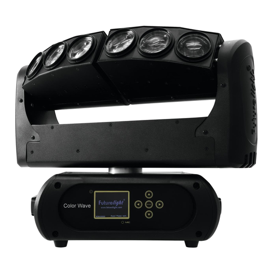
Geräteübersicht (1) Projektorarm (2) Linse/LED (3) LED-Leiste (4) Projektorkopf (5) Base (6) Gummifuß (7) Control Board (8) LCD-Anzeige (9) Mikrofon (10) Pfeil-Taste nach links (11) Pfeil-Taste nach unten (12) Enter-Taste (13) Pfeil-Taste nach rechts (14) Pfeil-Taste nach oben (15) Tragegriff (16) Gehäuseschraube (17) 5-poliger DMX-Eingang (18) 3-poliger DMX-Eingang... -
Page 9: Installation
INSTALLATION Projektormontage Die Aufhängevorrichtungen des Projektors muss so gebaut und bemessen sein, dass sie 1 Stunde lang ohne dauernde schädliche Deformierung das 10-fache der Nutzlast aushalten kann. Die Installation muss immer mit einer zweiten, unabhängigen Aufhängung, z. B. einem geeigneten Fangnetz, erfolgen. - Page 10 Die Projektorbase lässt sich auf zwei verschiedene Arten montieren. Das Gerät kann direkt auf den Boden gestellt werden oder in jeder möglichen Position im Trussing installiert werden, ohne seine funktionellen Eigenschaften zu verändern. Beachten Sie bitte bei der vertikalen Installation im Trussing, dass der Omega-Halter immer parallel zum Trussing verläuft.
-
Page 11: Anschluss An Den Dmx-512 Controller / Verbindung Projektor - Projektor
Anschluss an den DMX-512 Controller / Verbindung Projektor – Projektor Achten Sie darauf, dass die Adern der Datenleitung an keiner Stelle miteinander in Kontakt treten. Die Geräte werden ansonsten nicht bzw. nicht korrekt funktionieren. Beachten Sie, dass die Startadresse abhängig vom verwendeten Controller ist. Unbedingt Bedienungsanleitung des verwendeten Controllers beachten. -
Page 12: Anschluss Ans Netz
Betrieb auf. Während des Reset justieren sich die Motoren aus und das Gerät ist danach betriebsbereit. Stand Alone-Betrieb Die COLOR WAVE lässt sich im Stand Alone-Betrieb ohne Controller einsetzen. Trennen Sie dazu die COLOR WAVE vom Controller und rufen Sie das vorprogrammierte Programm auf. Bitte beachten Sie weitere Hinweise unter Control Board. -
Page 13: Dmx-Gesteuerter Betrieb
Steuerkanäle 22 bis 42. Bitte vergewissern Sie sich, dass sich die Steuerkanäle nicht mit anderen Geräten überlappen, damit die COLOR WAVE korrekt und unabhängig von anderen Geräten in der DMX-Kette funktioniert. Werden mehrere COLOR WAVEs auf eine Adresse definiert, arbeiten sie synchron. -
Page 14: Dmx-Protokoll
DMX-Protokoll Mode/Channel Decimal Hexad. Percentage Eigenschaft St. Ex. Horizontale Bewegung (PAN) Wenn Sie den Regler verschieben, bewegen Sie den Kopf horizontal (PAN). Allmähliches Einstellen des 0% 100% F Kopfes bei langsamen Schieben des Reglers (0-255, 128-Mitte). Der Kopf kann an jeder gewünschten Einstellung angehalten werden. - Page 15 DF 13% 87% F Strobe-Effekt mit zunehmender Geschwindigkeit 224 255 E0 FF 88% 100% S Offen Öffnender Puls-Effekt S Geschlossen DF 13% 87% F Strobe-Effekt mit zunehmender Geschwindigkeit 224 255 E0 FF 88% 100% S Offen Schließender Puls-Effekt S Geschlossen DF 13% 87% F Strobe-Effekt mit zunehmender Geschwindigkeit 224 255 E0...
- Page 16 Rainboweffekt rückwärts 0% 100% F Mit zunehmender Geschwindigkeit Farbwechsel linear & Schneller Farbsprung S Schwarz F Rot 100% / Grün zunehmend / Blau 0% / Weiß 0% 3F 13% 25% F Rot abnehmend / Grün 100% / Blau 0% / Weiß 0% 5D 25% 36% F Rot 0% / Grün 100% / Blau zunehmend / Weiß...
- Page 17 244 245 F5 96% 96% S Rot 246 247 F7 96% 97% S Grün 248 249 F9 97% 98% S Blau 250 251 FA FB 98% 98% S Weiß 252 255 FC FF 99% 100% S Alle Farben LED 2 - Farbvoreinstellungen S Schwarz F Rot 100% / Grün zunehmend / Blau 0% / Weiß...
- Page 18 214 243 D6 F3 84% 95% F Rot 100% / Grün 0% / Blau 0% / Weiß abnehmend 244 245 F5 96% 96% S Rot 246 247 F7 96% 97% S Grün 248 249 F9 97% 98% S Blau 250 251 FA FB 98% 98% S Weiß...
-
Page 19: Control Board
Control Board Das Control Board bietet mehrere Möglichkeiten: so lassen sich z. B. die DMX-Startadresse eingeben, das vorprogrammierte Programm abspielen oder ein Reset durchführen. Drücken Sie die Enter-Taste, so dass sich das Display einschaltet. Durch Drücken der geeigneten Pfeil- Taste (nach unten, nach oben, nach links und nach rechts) können Sie sich im Hauptmenü bewegen. Zur Auswahl des gewünschten Menüpunktes drücken Sie die Enter-Taste. -
Page 20: Connect
Standard Extended Benutzerdefinierte User Mode Basic-8bit Kanalreihenfolge Basic-16bit Users User Max Channel = XX Preset-Benutzerd. Edit User PAN = CH01 ... Effektradjustierung; --Password-- Password=XXX Calibration Standardposition Color ... Color =XXX ... Passwort „050“ Name Name --Password-- Passwort „050“ Fixture ID ... -
Page 21: Information
Information Time information Betriebsstunden Gerät seit dem Einschalten (current) Mit dieser Funktion lassen sich die temporären Betriebsstunden des Gerätes seit dem Einschalten auslesen. Auf dem Display erscheint “XXXX”, “X“ steht für die Anzahl der Stunden. Der Zähler wird beim Abschalten auf 0 zurückgesetzt. - Page 22 UI Set Mikrofonempfindlichkeit Mit dieser Funktion lässt sich die Mikrofonempfindlichkeit zwischen 0 % und 99 % einstellen. • Wählen Sie “Mic Sens” durch Drücken der Up/Down-Tasten. • Drücken Sie die Up/Down-Taste, um die gewünschte Empfindlichkeit einzustellen. • Drücken Sie die Enter-Taste zur Bestätigung. Auto-Modus wenn kein DMX Mit der Funktion "No Signal“...
-
Page 23: Program
Calibration Effektradjustierung Mit dieser Funktion lassen sich die Effekträder auf die korrekten Ausgangspositionen kalibrieren. Das Passwort für diese Funktion ist „050“. Fixture ID Mit dieser Funktion können Sie diverse Menüpunkte per RDM abrufen. Das Gerät unterstützt RDM. Die Abkürzung RDM steht für "Remote Device Management" und macht eine Fernabfrage bzw. - Page 24 Szenen automatisch aufzeichnen Das Gerät verfügt über einen internen DMX-Recorder, mit dem sich programmierte Szenen aus dem DMX- Controller auf das Gerät übertragen lassen. Stellen Sie die gewünschten Szenen-Nummern über die Up/Down-Tasten ein (von – bis). Wenn Sie nun die Szenen auf Ihrem Controller aufrufen, werden diese automatisch auf das Gerät übertragen.
-
Page 25: Fehlermeldungen
Beispiel: Programm 2 enthält die Szenen: 10, 11, 12, 13; Programm 4 enthält die Szenen: 8, 9, 10 und Programm 6 enthält die Szenen: 12, 13, 14, 15, 16 Chase Part 1 ist Programm 2; Chase Part 2 ist Programm 3; Chase Part 3 ist Programm 6 Die 3 Slave-Gruppen durchlaufen das Auto Programm in bestimmten Zeitabschnitten, wie die folgende Abbildung zeigt:... -
Page 26: Sicherungswechsel
Dabei muss unter anderem auf folgende Punkte besonders geachtet werden: 1) Alle Schrauben, mit denen das Gerät oder Geräteteile montiert sind, müssen fest sitzen und dürfen nicht korrodiert sein. 2) An Gehäuse, Befestigungen und Montageort (Decke, Abhängung, Traverse) dürfen keine Verformungen sichtbar sein. -
Page 27: Technische Daten
TECHNISCHE DATEN Spannungsversorgung: 100-240 V AC, 50/60 Hz ~ Gesamtanschlusswert: 120 W DMX-Steuerkanäle: 17/18/20/21 DMX512-Anschluss: 5-pol. und 3-pol. XLR Musiksteuerung: über eingebautes Mikrofon Blitzrate: 20 Hz LED-Typ: 10-W-QCL Anzahl der LEDs: Max. Schwenkbewegung (PAN): 630° Max. Kippbewegung (TILT): 240° Abstrahlwinkel: 2,5°... -
Page 28: Introduction
- pass this manual on to every further owner or user of the product - download the latest version of the user manual from the Internet INTRODUCTION Thank you for having chosen a FUTURELIGHT COLOR WAVE. You will see you have acquired a powerful and versatile device. Unpack your COLOR WAVE. -
Page 29: Safety Instructions
SAFETY INSTRUCTIONS CAUTION! Be careful with your operations. With a dangerous voltage you can suffer a dangerous electric shock when touching the wires! This device has left our premises in absolutely perfect condition. In order to maintain this condition and to ensure a safe operation, it is absolutely necessary for the user to follow the safety instructions and warning notes written in this user manual. -
Page 30: Operating Determinations
running, the device must be checked by a specialist if the liquid has reduced any insulation. Reduced insulation can cause mortal electrical shock. There must never be any objects entering into the device. This is especially valid for metal parts. If any metal parts like staples or coarse metal chips enter into the device, the device must be taken out of operation and disconnected immediately. -
Page 31: Description Of The Device
Make sure that the area below the installation place is blocked when rigging, derigging or servicing the fixture. For overhead use (mounting height >100 cm), always fix the fixture with an appropriate safety-rope. Fix the safety-rope at the correct fixation points only. The safety-rope must never be fixed at the transport handles! Only operate the fixture after having checked that the housing is firmly closed and all screws are tightly fastened. -
Page 32: Overview
Overview (1) Yoke (2) Lens/LED (3) LED bar (4) Projector head (5) Base (6) Rubber foot (7) Control Board (8) LC display (9) Microphone (10) Arrow button left (11) Arrow button down (12) Enter button (13) Arrow button right (14) Arrow button up (15) Carrying handle (16) Housing screw (17) 5-pin DMX input... -
Page 33: Installation
INSTALLATION Rigging The installation of the projector has to be built and constructed in a way that it can hold 10 times the weight for 1 hour without any harming deformation. The installation must always be secured with a secondary safety attachment, e.g. an appropriate catch net. This secondary safety attachment must be constructed in a way that no part of the installation can fall down if the main attachment fails. - Page 34 The fixture’s base enables to be mounted in two ways. The Moving-Head can be placed directly on the stage floor or rigged in any orientation on a truss without altering its operation characteristics (see the drawing). Make sure that the Omega-holder is always in line with the truss structure when installing the device vertically.
-
Page 35: Dmx-512 Connection / Connection Between Fixtures
DMX-512 connection / connection between fixtures The wires must not come into contact with each other, otherwise the fixtures will not work at all, or will not work properly. Please note, the starting address depends upon which controller is being used. Only use a DMX-cable and 3-pin or 5-pin XLR-plugs and connectors in order to connect the controller with the fixture or one fixture with another. -
Page 36: Connection With The Mains
With the power switch, you can switch the device on and off. After you connected the effect to the mains, the COLOR WAVE starts running. During the reset, the motors are trimmed and the device is ready for use afterwards. -
Page 37: Dmx-Controlled Operation
The Control Board allows you to assign the DMX starting address, which is defined as the first channel from which the COLOR WAVE will respond to the controller. If you set, for example, the address in the 22 channel mode to channel 22, the COLOR WAVE will use the channel 22 to 42 for control. -
Page 38: Dmx-Protocol
DMX-protocol Mode/Channel Decimal Hexad. Percentage Feature St. Ex. Horizontal movement (PAN) Push slider up in order to move the head horizontally (PAN). Gradual head adjustment 100% from one end of the slider to the other (0- 255, 128-center). The head can be stopped at any position you wish. - Page 39 Shutter, strobe Normal Shutter Functions Close Strobe effect with increasing speed 100% Open Opening pulse effect Close Strobe effect with increasing speed 100% Open Closing pulse effect Close Strobe effect with increasing speed 100% Open Random strobe effect Close Strobe effect with increasing speed 100% Open Shutter sequence...
- Page 40 White 5600 K 100% White 8000 K Forwards rainbow effect 100% With increasing speed Backwards rainbow effect 100% With increasing speed Color-change linear & Color Bounce Black Red 100% / green increasing / blue 0% / white 0% Red decreasing / green 100% / blue 0% / white 0% Red 0% / green 100% / blue increasing / white 0%...
- Page 41 LED 1 - color presets Black Red 100% / green increasing / blue 0% / white 0% Red decreasing / green 100% / blue 0% / white 0% Red 0% / green 100% / blue increasing / white 0% Red 0% / green decreasing / blue 100% / white 0% Red 0% / green 0% / blue 100% / white increasing...
- Page 42 white 0% Red 0% / green 0% / blue 100% / white increasing Red 0% / green 0% / blue decreasing / white 100% Red increasing / green 0% / blue 0% / white 100% Red 100% / green 0% / blue 0% / white decreasing Green Blue...
- Page 43 Green Blue White 100% All colors LED 6 - color presets Black Red 100% / green increasing / blue 0% / white 0% Red decreasing / green 100% / blue 0% / white 0% Red 0% / green 100% / blue increasing / white 0% Red 0% / green decreasing / blue 100% / white 0%...
-
Page 44: Control Board
Control Board The Control Board offers several features: you can simply set the starting address, run the pre-programmed program or make a reset. The main menu is accessed by pressing Enter until the display is lit. Browse through the menu by pressing the arrow buttons (up, down, left, right). -
Page 45: Connect
Standard Extended User’s mode to User Mode Basic-8bit change channel Basic-16bit numbers Users User Max Channel = XX Preset User modes Edit User PAN = CH01 ... Wheel adjustment --Password-- Password=XXX Calibration to standard position Color ... Color =XXX ... -
Page 46: Information
Information Time information Current With this function, you can display the temporary running time of the device from the last power on. The display shows “XXXX”, “X“ stands for the number of hours. The counter is reset after turning the device off. Fixture Life With this function, you can display the running time of the device. - Page 47 UI Set Mic sensitivity With this function, you can select the desired microphone sensitivity between 0 % and 99 %. • Select “Mic Sens” by pressing Up or Down. • Press the Enter-button. • Press Up or Down to select the desired sensitivity. •...
-
Page 48: Program
Calibration With this function, you can calibrate and adjust the effect wheels to their correct positions. The password for this function is „050“. Fixture ID With this function you can call up various submenus via RDM. This device is RDM ready. RDM stands for "Remote Device Management" and makes remote control of devices connected to the DMX-bus possible. - Page 49 Excursion: A Master unit can send up to 3 different data groups to the Slave units, i.e. a Master unit can start 3 different Slave units, which run 3 different programs. The Master unit sends the 3 program parts in a continuous loop. The Slave unit receives data from the Master unit according to the group which the Slave unit was assigned to.
-
Page 50: Error Messages
Example: Program 2 includes scenes: 10, 11, 12, 13; Program 4 includes scenes: 8, 9, 10 and Program 6 includes scenes: 12, 13, 14, 15, 16 Chase Part 1 is Program 2; Chase Part 2 is Program 3; Chase Part 3 is Program 6 The 3 Slave groups run the Auto Program in certain time segments, as shown in the following picture: Error Messages When you turn on the fixture, it will make a reset first. -
Page 51: Cleaning And Maintenance
CLEANING AND MAINTENANCE The operator has to make sure that safety-relating and machine-technical installations are inspected by an expert after every four years in the course of an acceptance test. The operator has to make sure that safety-relating and machine-technical installations are inspected by a skilled person once a year. -
Page 52: Technical Specifications
TECHNICAL SPECIFICATIONS Power supply: 100-240 V AC, 50/60 Hz ~ Power consumption: 120 W DMX control channels: 17/18/20/21 DMX512 connection: 5-pin and 3-pin XLR Sound-control: via built-in microphone Flash-rate: 20 Hz LED type: 10 W QCL Number of LEDs: Maximum PAN-movement: 630°...
Need help?
Do you have a question about the COLOR WAVE and is the answer not in the manual?
Questions and answers