
Subscribe to Our Youtube Channel
Related Manuals for Arbor Technology Rigid-314


Summary of Contents for Arbor Technology Rigid-314
- Page 1 Rigid-314 Extreme Rugged Fanless Box Computer w/ Intel Atom D2550 Platform ® User’s Manual Version 1.0 2013.08 P/N: 4016313100100P...
-
Page 2: Revision History
Revision History Version Date Description 2013/08 initial release... -
Page 3: Table Of Contents
Contents Revision History ...............II Preface....................iii Copyright Notice ..................iii Declaration of Conformity ...............iii CE ....................iii FCC Class B ..................iii RoHS ....................iv SVHC / REACH ................iv Important Safety Instructions ..............v Warning ....................vi Replacing the Lithium Battery ..............vi Technical Support .................. - Page 4 Contents 4.2. Mount the Computer ..............33 4.2.1. Wall-Mount (optional) ............33 4.2.2. VESA-Mount (optional) ............34 4.2.3. DIN Rail (optional) ............... 36 4.3. Ground the Box PC ................ 38 4.4. Wire the DC-Input Power Source ........... 39 Chapter 5 - BIOS ................41 5.1.
-
Page 5: Preface
Preface Preface Copyright Notice All Rights Reserved. The information in this document is subject to change without prior notice in order to improve the reliability, design and function. It does not represent a commitment on the part of the manufacturer. Under no circumstances will the manufacturer be liable for any direct, indirect, special, incidental, or consequential damages arising from the use or inability to use the product or documentation, even if advised of the possibility of such... -
Page 6: Rohs
-- Consult the dealer or an experienced radio/TV technician for help. RoHS ARBOR Technology Corp. certifies that all components in its products are in compliance and conform to the European Union’s Restriction of Use of Haz- ardous Substances in Electrical and Electronic Equipment (RoHS) Directive 2002/95/EC. -
Page 7: Important Safety Instructions
Preface Important Safety Instructions Read these safety instructions carefully 1. Read all cautions and warnings on the equipment. 2. Place this equipment on a reliable surface when installing. Dropping it or letting it fall may cause damage 3. Make sure the correct voltage is connected to the equipment. 4. -
Page 8: Warning
Preface Warning The Box PC and its components contain very delicately Integrated Circuits (IC). To protect the Box PC and its components against damage caused by static electricity, you should always follow the precautions below when han- dling it: 1. Disconnect your Box PC from the power source when you want to work on the inside. -
Page 9: Warranty
Preface Warranty This product is warranted to be in good working order for a period of one year from the date of purchase. Should this product fail to be in good working order at any time during this period, we will, at our option, replace or repair it at no additional charge except as set forth in the following terms. - Page 10 This page is intentionally left blank. - viii -...
-
Page 11: Chapter 1 - Introduction
Introduction Chapter 1 Introduction Chapter 1 - Introduction - 1 -... -
Page 12: The Product
Introduction 1.1. The Product The Rigid-314 is a wide-temperature computer to feature the basic and essential features required for industrial field. Loaded with soldered onboard Intel Atom™ D2550 1.86GHz processor and ® chipset of Intel NM10 PCH, the fanless computer consumes low power while ®... -
Page 13: Specifications
Introduction 1.3. Specifications System Kernel Processor Soldered onboard Intel Atom™ D2550 1.86GHz processor ® Chipset Intel NM10 PCH ® Graphics Integrated Intel GMA 3650 ® 1 x 204-pin DDR3 SO-DIMM socket, supporting 800/1066MHz SDRAM up to 4GB System Memory 2GB WT DDR3 memory module installed Serial ATA 1 x Serial ATA port with 300MB/s HDD transfer rate Ethernet Controller... -
Page 14: Inside The Package
Upon opening the package, carefully inspect the contents. If any of the items is missing or damaged, contact your local dealer or distributor. The package should contain the following items: 1 x Rigid-314 Extreme Rugged Fanless Computer 1 x Driver CD 1 x User’s Manual... -
Page 15: Ordering Information
Introduction 1.5. Ordering Information Rigid-314 Fanless embedded controller 1.5.1. Optional Accessories The following items are normally optional, but some vendors may include them as a standard package, or some vendors may not carry all the items. DRK-001 Din rail kit of FPC series... -
Page 16: Configure-To-Order Service
Introduction 1.5.2. Configure-to-Order Service Make the computer more tailored to your needs by selecting one or more components from the list below to be fabricated to the computer. SSD-25040 Intel 2.5” 40GB SATAII SSD kit ® HSPA-SI1400 HSUPA 3.75G module kit & internal wiring Intel Centrino Advanced-N 6205 WiFi module w/... -
Page 17: Chapter 2 - Getting Started
Getting Started Chapter 2 Getting Started Chapter 2 - Getting Started - 7 -... -
Page 18: Dimensions
Getting Started 2.1. Dimensions The following illustration shows the dimension of Rigid-314, with the measurements in width, depth, and height called out. Unit: mm - 8 -... -
Page 19: Take A Tour
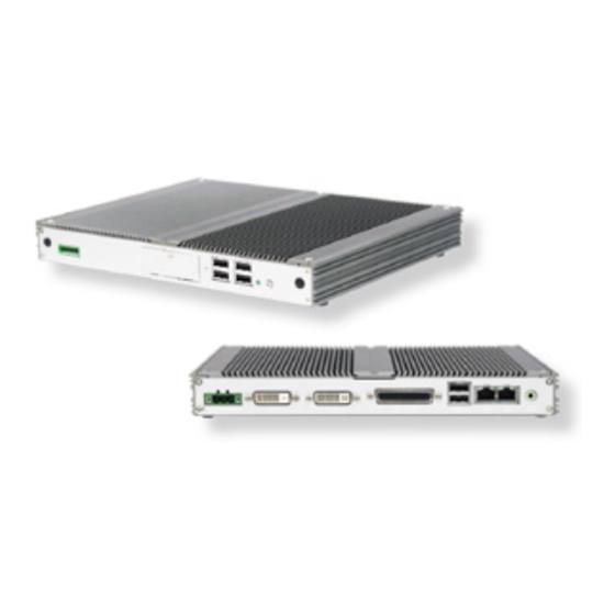
Getting Started 2.2. Take a Tour The computer has some I/O ports, status LED light and controls on the front and rear panels. The following illustrations show all the components called out for Rigid-314. 2.2.1. Front View Digital I/O power USB 2.0... -
Page 20: Driver Installation Notice
Getting Started 2.3. Driver Installation Notice The computer supports the operating systems of Windows 7 and XP. For these operating systems, find the necessary device drivers on the CD that comes with your purchase. For different operating systems, the installation of drivers may vary slightly, but generally they are similar. -
Page 21: Chapter 3 - System Configuration
System Configuration Chapter 3 System Configuration Chapter 3 - System Configuration - 11 -... -
Page 22: Board Layout
System Configuration 3.1. Board Layout The main board FMB-i2509-WT comes with some connectors to join devices and jumpers to alter hardware configuration. The following in this chapter will explicate each of these components one-by-one. AUDIO4 DVI1 DVI2 USB1 PWRIN1 LAN1 SW5 SW4 JCP1 SW10 SW9... -
Page 23: Jumper And Connectors
System Configuration 3.2. Jumper and Connectors 3.2.1. Jumper JBAT1 JPWR1 Function: clear CMOS setting Function: AT/ATX power type selector Jumper Type: onboard 2.54mm Jumper Type: onboard 2.54mm pitch pitch 1x3-pin header 1x3-pin header Setting: Setting: Description Description keeps CMOS AT mode (default) ATX mode clears CMOS... -
Page 24: System Configuration
System Configuration SW4/5, SW8/11, SW9/10 Function: RS-232/422/485 mode selectors for COM3~4 Setting: SW4, 8, 9 control COM3; SW5, 11, 10 control COM4. User must set the same group of switches to the same mode simultaneously. SW4/5 SW8/11 RS-232 RS-422 RS-485 RS-232 RS-422 RS-485... - Page 25 System Configuration SW12 Function: RS-422/485 termination Setting: Without 120 OHM With 120 OHM (default) AUDIO4 DVI1 DVI2 USB1 PWRIN1 LAN1 SW5 SW4 JCP1 SW10 SW9 SW12 SW11 SW8 SATA0 1 2 3 4 DIMM2 JPWR1 JBAT1 PC17 SIM1 PWBT1 DIO1 USB3 USB2 HDDLED...
-
Page 26: Pin Description
System Configuration JCP1 JV1~4 Function: COM Port power selector Function: RI/5V/12V (Pin selectors for COM1~4 Jumper Type: onboard 2.54mm pitch 1x3-pin header Jumper Type: onboard 2.54mm pitch 1x3-pin header Setting: Setting: JV1~4 correspond to Description COM1~4 respectively. Description 5V (default) normal (default) COMPOWER... -
Page 27: Connectors
System Configuration 3.2.2. Connectors SATA0 Function: S-ATA1 connector Connector Type: SATA port with data + power vertical connector (7+15pin) Description Description Description S1 GND P1 +3.3V P8 +5VS S2 TX+ P2 +3.3V P9 +5VS S3 TX- P3 +3.3V P10 GND S4 GND P4 GND P11 NC... - Page 28 System Configuration PC17 Function: CFast Card Type I/II socket Connector Type: 7+17-pin CFast Card connector consisting of a SATA compatible 7-pin signal connector and a 17-pin power control connector. Segment Name Type Description SATA SGND Signal GND Ground for signal integrity SATA SATA Differential Signal Pair A...
- Page 29 System Configuration SIM1 DIMM2 Function: SIM card holder with a Function: 204-Pin DDR3 SO-DIMM hinged cover socket Description AUDIO4 DVI1 DVI2 USB1 PWRIN1 LAN1 SW5 SW4 JCP1 SW10 SW9 SW12 SW11 SW8 SATA0 1 2 3 4 DIMM2 JPWR1 JBAT1 PC17 SIM1 PWBT1...
- Page 30 System Configuration Function: PCI Express MiniCard socket Connector Type: Onboard 0.8mm pitch 52-pin edge card connector Desc. Desc. Desc. Desc. Wake UIM_RESET +3.3V +1.5V +3.3V COEX1 UIM_VPP LED_WWAN# UIM_C8/Reserved SMB_CLK COEX2 PETn0 LED_WLAN# +1.5V UIM_C4/Reserved SMB_DATA Reserved CLKREQ# W_Disable# PETp0 LED_WPAN# UIM_PWR Reserved...
- Page 31 System Configuration LAN1 AUDIO4 Function: RJ-45 Ethernet connectors Function: audio output Connector Type: 10/100/1000Mbps Connector Type: 3.5φ Fast Ethernet green audio jack w/ shield Pin Description PWRIN1 MDI0 Function: DC adapter power input MDI0# Pin Description MDI1 1 2 3 MDI1# VCC 9~36V MDI2...
- Page 32 System Configuration CN2 (COM1 ~ COM4) Function: RS-232 (COM1~2); RS-232/422/485 (COM3~4) Connector Type: DB-44 female connector Pin1~9 define and correspond to COM1’s Pin1~9 respectively; Pin11~19 define COM2’s Pin1~9; Pin21~29 define COM3’s Pin1~9; Pin31~39 define COM4’s Pin1~9. COM1~2 do not support RS-422/485 modes. That is to say, the pin definition of RS-422 &...
- Page 33 System Configuration DVI1 Function: DVI-I display connector Connector Type: 29-pin DIP-type female connector Description Description Description T.M.D.S DATA 2- T.M.D.S DATA 5+ T.M.D.S DATA 1/3 SHIELD T.M.D.S DATA 2+ T.M.D.S DATA 3- T.M.D.S CLOCK SHIELD T.M.D.S DATA 3+ T.M.D.S CLOCK+ T.M.D.S DATA 2/4 SHIELD T.M.D.S DATA 4- +5V Power...
- Page 34 System Configuration DVI2 Function: DVI-D display connector Connector Type: 24-pin DIP-type female connector Description Description Description TMDS DATA2- TMDS DATA1- TMDS DATA0- TMDS DATA2+ TMDS DATA1+ TMDS DATA0+ TMDS DATA2/4 shield TMDS DATA1/3 shield TMDS DATA0/5 shield (NC) TMDS DATA4- (NC) TMDS DATA3- (NC) TMDS DATA5- (NC) TMDS DATA4+...
- Page 35 System Configuration USB1~3 Function: USB2.0 Port 0~5 Connector Type: double stack USB2.0 type A connector USB1 controls USB2.0 Port 0/1; USB2 controls USB2.0 Port 2/3; USB3 controls USB2.0 Port 4/5. Description 1 2 3 4 USB D- USB D+ 1 2 3 4 AUDIO4 DVI1 DVI2...
- Page 36 System Configuration Function: 6-bit digital I/O connector (3 in/3 out) Connector Type: onboard 2.54mm pitch 1x8-pin header Description Description DIO0 DIO4 DIO1 DIO5 DIO2 +V5S DIO3 AUDIO4 DVI1 DVI2 USB1 PWRIN1 LAN1 SW5 SW4 JCP1 SW10 SW9 SW12 SW11 SW8 SATA0 1 2 3 4 DIMM2...
-
Page 37: Chapter 4 - Installation And Maintenance
Installation and Maintenance Chapter 4 Installation and Maintenance Chapter 4 - Installation and Maintenance - 27 -... -
Page 38: Install Hardware
Installation and Maintenance 4.1. Install Hardware The computer is constructed based on modular design to make it easy for users to add hardware or to maintain the computer. The following sections will guide you through simple hardware installations. 4.1.1. Remove Top Cover Turn off the computer. -
Page 39: Install Memory Module
Installation and Maintenance 4.1.2. Install Memory Module side notch side notch key notch The main board has one dual inline memory module (DIMM) socket. Load the computer with a memory module of higher capacity to make programs run faster. The memory module for the computer’s SO-DIMM socket should be a 204-pin DDR3 with a “key notch”... -
Page 40: Install Hdd Or Ssd
Installation and Maintenance 4.1.3. Install HDD or SSD 1. Find HDD bracket on main board. Unscrew its four corners where red circles locate. Carefully draw out the bracket as arrow directs. 2. Mount HDD on bracket and lock it. 3. Fully insert the bracket into driver bay and secure its corners. - 30 -... -
Page 41: Install Wifi Or Hsupa Modules (Optional)
Installation and Maintenance 4.1.4. Install WiFi or HSUPA Modules (optional) The computer also comes with a Mini-card socket for WiFi (WIFI-IN1300) or HSUPA (HSPA-SI1400) module. See 1.5.1. Optional Accessories and contact your regional dealer to order these modules. HSPA-SI1400 HSUPA 3.75G module kit & internal wiring WIFI-IN1300 Intel Centrino... - Page 42 Installation and Maintenance 2. Push the CFast/SIM card into their slots to the end according to installation illustration beside slots. Close the card door and secure the screw. CFast card SIM card 3. To uninstall the CFast/SIM card, just push inwardly to eject them. - 32 -...
-
Page 43: Mount The Computer
Installation and Maintenance 4.2. Mount the Computer Integrate the computer to where it works by mounting it to a wall in the sur- roundings or to the rear of a display monitor or to DIN rail, which relies on VMK-3100, DRK-001 or WMK-3100 in optional accessories list. VMK-3100 VESA mount kit DRK-001... -
Page 44: Vesa-Mount (Optional)
Installation and Maintenance 2. Use the same screws to secure WMK-3100 to the box PC. Fix the computer on wall through the holes at both sides. secure on wall through the holes secure on wall through the holes 4.2.2. VESA-Mount (optional) The computer can be mounted to LCD monitor’s rear side that is VESA 100 compliant. - Page 45 Installation and Maintenance 2. Secure VMK-3100 firmly to the monitor. 3. Hang the computer (mounted with WMK-3100, see the last section) onto VMK-3100. Secure the box PC to VESA bracket as below. - 35 -...
-
Page 46: Din Rail (Optional)
Installation and Maintenance 4.2.3. DIN Rail (optional) 1. Remove the box PC’s rubber feet as described in Section 4.2.1. Wall- Mount (optional). Align the screw holes of DIN rail bracket covered in DRK-001 with the ones on the bottom side of the computer. Secure the bracket to the computer.. - Page 47 Installation and Maintenance 2. Meet DIN rail clip with DIN rail itself. Hook DIN rail spring on one edge of DIN rail and press the box PC into DIN rail until it's fixed firmly. vertical direction horizontal direction - 37 -...
-
Page 48: Ground The Box Pc
Installation and Maintenance Remove the Box PC from DIN Rail Make sure power is off, and disconnect all cables from the computer. Carefully hold the box PC and push DIN rail spring downwards. As clip releases, lift the box PC off DIN rail. 4.3. -
Page 49: Wire The Dc-Input Power Source
Installation and Maintenance 4.4. Wire the DC-Input Power Source Warning Only trained and qualified personnel are allowed to install or replace this equipment. Follow the instructions below for connecting the computer to a DC-input power source. 1. Before wiring, make sure the power source is disconnected. 2. - Page 50 This page is intentionally left blank. - 40 -...
-
Page 51: Chapter 5 - Bios
BIOS Chapter 5 BIOS Chapter 5 - BIOS - 41 -... - Page 52 BIOS The BIOS Setup utility for the computer is featured by American Megatrends Inc to configure the system settings stored in the system’s BIOS ROM. The BIOS is activated once the computer powers on. To enter the BIOS Setup utility, keep hitting the “Delete” key upon powering on the computer.
-
Page 53: Main
Data BIOS Vendor American Megatrends elements. Core Version 4.6.5.1 Compliancy UEFI 2.3; PI 1.2 BIOS Version RIGID-314 1.00 Build Date and Time 04/22/2013 10:27:43 System Date [Fri 05/31/2013] System Time [17:31:42] Access Level Administrator →←: Select Screen ↓↑: Select Item... -
Page 54: Advanced
BIOS Set the system time. The time format is: Hour: 00 to 23 ► System Time Minute: 00 to 59 Second: 00 to 59 5.2. Advanced Access the Advanced menu to manage the computer’s system configuration including the Super IO chip. Aptio Setup Utility - Copyright (C) 2011 American Megatrends, Inc. -
Page 55: Acpi Settings
BIOS USB Configuration See Section 5.2.5. USB Configuration Super IO Configuration See Section 5.2.6. Super IO Configuration H/W Monitor See Section 5.2.7. H/W Monitor 5.2.1. ACPI Settings Aptio Setup Utility - Copyright (C) 2011 American Megatrends, Inc. Advanced ACPI Settings Enables or Disables System ability to Enable Hibernation... -
Page 56: S5 Rtc Wake Settings
BIOS 5.2.2. S5 RTC Wake Settings Aptio Setup Utility - Copyright (C) 2011 American Megatrends, Inc. Advanced Wake system with Fixed Time [Disabled] Enable or disable System wake on alarm Wake system with Dynamic Time event. When enabled, [Disabled] System will wake on the hr::min::sec specified →←: Select Screen... -
Page 57: Cpu Configuration
BIOS 5.2.3. CPU Configuration Aptio Setup Utility - Copyright (C) 2011 American Megatrends, Inc. Advanced Enabled for Windows XP CPU Configuration and Linux(OS optimized for Hyper-Threading Processor Type Intel(R) Atom(TM) CPU Technology) and EMT64 Supported Disabled for other OS Processor Speed 1865 MHz (OS not optimized for System Bus Speed... -
Page 58: Ide Configuration
BIOS 5.2.4. IDE Configuration Aptio Setup Utility - Copyright (C) 2011 American Megatrends, Inc. Advanced SATA Port0 WDC WD3200BPVT (320.0 SATA Ports (0-3) Device Names if SATA Port1 Not Present Present and Enabled. [Enabled] SATA Controller(s) [AHCI] Configure SATA as [No Limit] Port0 Speed Limit [No Limit]... -
Page 59: Usb Configuration
BIOS 5.2.5. USB Configuration Aptio Setup Utility - Copyright (C) 2011 American Megatrends, Inc. Advanced USB Configuration Enables Legacy USB support. AUTO option disables legacy USB Devices: support if no USB 1 Keyboard, 1 Mouse devices are connected. DISABLE option will [Enabled] Legacy USB Support keep USB devices... -
Page 60: Super Io Configuration
BIOS USB mass storage device Start Unit command Device reset time-out time-out. Options: 10/20 (default)/30/40 sec ► Maximum time the device will take before it properly reports itself to the Host Controller. ‘Auto’ Device power-up delay uses default value: for a Root port it is 100 ms, for a Hub port the delay is taken from Hub descriptor. - Page 61 BIOS Serial Port 1~4 Configuration Aptio Setup Utility - Copyright (C) 2011 American Megatrends, Inc. Advanced Serial Port 1 Configuration Enable or Disable Serial Port (COM) Serial Port [Enabled] Device Settings IO=3F8h; IRQ=4; Change Settings [IO=3F8h; IRQ=4;] →←: Select Screen ↓↑: Select Item Enter: Select +/-: Change Opt.
-
Page 62: H/W Monitor
BIOS 5.2.7. H/W Monitor Aptio Setup Utility - Copyright (C) 2011 American Megatrends, Inc. Advanced Pc Health Status System Temperature : +41°c CPU Temperature : +42°c Vcore : +1.192 V : +4.918 V +1.05V : +1.032 V +1.5V : +1.496 V +12V : +11.880 V +3.3V... -
Page 63: Chipset
BIOS 5.3. Chipset Aptio Setup Utility - Copyright (C) 2011 American Megatrends, Inc. Main Advanced Boot Security Save & Exit Chipset ► Host Bridge Host Bridge Parameters ► South Bridge →←: Select Screen ↓↑: Select Item Enter: Select +/-: Change Opt. F1: General Help F2: Previous Values F9: Optimized Defaults... -
Page 64: Host Bridge
BIOS 5.3.1. Host Bridge Aptio Setup Utility - Copyright (C) 2011 American Megatrends, Inc. Chipset ► Intel IGD Configuration Config Intel IGD Settings. ******* Memory Information ******* 1067 MHz(DDR3) Memory Frequency 4096 MB Total Memory Not Present DIMM#0 4096 MB DIMM#1 →←: Select Screen ↓↑: Select Item... -
Page 65: Intel Igd Configuration
BIOS Intel IGD Configuration Aptio Setup Utility - Copyright (C) 2011 American Megatrends, Inc. Chipset Intel IGD Configuration Auto disable IGD upon Auto Disable IGD [Enabled] external GFX detected. IGFX - Boot Type [DVI-I] →←: Select Screen ↓↑: Select Item Enter: Select +/-: Change Opt. -
Page 66: South Bridge
BIOS 5.3.2. South Bridge Aptio Setup Utility - Copyright (C) 2011 American Megatrends, Inc. Chipset ► TPT Devices Enable/Disable Intel(R) IO Controller [1-2 Seconds] SLP_S4 Assertion Width Hub (TPT) devices [Power On] Restore AC Power LOSS →←: Select Screen ↓↑: Select Item Enter: Select +/-: Change Opt. - Page 67 BIOS TPT Devices Aptio Setup Utility - Copyright (C) 2011 American Megatrends, Inc. Chipset Azalia Controller [HD Audio] Azalia Controller →←: Select Screen ↓↑: Select Item Enter: Select +/-: Change Opt. F1: General Help F2: Previous Values F9: Optimized Defaults F10: Save and Exit ESC: Exit Version 2.14.1219.
-
Page 68: Boot
BIOS 5.4. Boot Aptio Setup Utility - Copyright (C) 2011 American Megatrends, Inc. Main Advanced Chipset Security Save & Exit Boot Select the Keyboard Boot Configuration NumLock state [On] Bootup NumLock State [Disabled] Quiet Boot [Disabled] Fast Boot 07.65 CSM16 Module Version [Upon Request] GateA20 Active [Force BIOS]... -
Page 69: Security
BIOS 5.5. Security The Security menu sets up the administrator password. Once an administrator password is set up, this BIOS SETUP utility is limited to access and will ask for the password each time any access is attempted. Aptio Setup Utility - Copyright (C) 2011 American Megatrends, Inc. Main Advanced Chipset Boot... -
Page 70: Save & Exit
BIOS 5.6. Save & Exit Aptio Setup Utility - Copyright (C) 2011 American Megatrends, Inc. Main Advanced Chipset Boot Security Save & Exit Exit system setup Save Changes and Exit after saving the Discard Changes and Exit changes. Restore Defaults Boot Override →←: Select Screen ↓↑: Select Item... -
Page 71: Appendices
Appendices Appendices Appendices - 61 -... -
Page 72: A: Watchdog Timer (Wdt) Setting
Appendices A: Watchdog Timer (WDT) Setting WDT is widely applied to industry computers to monitor activities of CPU. The programmed application triggers WDT with adequate timer setting depending on its requirement. Before WDT counts down to zero, the functional system will reset the counter. -
Page 73: B: Digital I/O Setting
Appendices B: Digital I/O Setting Below are the source codes written in C, please take them for Digital I/O application examples. The default I/O address is 6Eh. /*----- Include Header Area -----*/ #include “math.h” #include “stdio.h” #include “dos.h” #define DELAY_TIME int SMB_PORT_AD = 0xF000;... - Page 74 Appendices unsigned char iData; unsigned char iFlag; int iError = 0; outportb(SMPORT+00, 0x1E); iFlag = inportb(SMPORT+00); if( iError++ > 0x8000 ) return 2; while( ( iFlag & 0x9F ) != 0 ); outportb(SMPORT+04, DeviceID+1); outportb(SMPORT+03, iREG_INDEX); outportb(SMPORT+02, 0x48); iError = 0; if( iError++ >...
-
Page 75: C: Hsupa Or Wifi Module Hardware Installation
Appendices C: HSUPA or WiFi Module Hardware Installation To be able to network with 3G, hardware-wise the computer needs the HSUPA module HSPA-SI1400 installed and a SIM card inserted (as described in Section 4.1.5. Install SIM or CFast Card). To use WiFi connection, the WiFi module HIFI- IN1300 should be installed instead. - Page 76 Appendices 3. Plug WiFi or HSUPA card to the socket’s connector by a slanted angle. Fully plug the module. Note the notch on the wireless module should meet the break of the connector. 4. Press down the module and fix the module in place using two screws. Remove the plastic plug from the computer’s front panel to create an antenna hole.
- Page 77 Appendices 5. Prepare RF cable, washer, nut included in WiFi or HSUPA module. The cable has an SMA connector on one end and an MHF connector on the other. SMA connector MHF connector washer 6. Connect RF cable’s MHF connector to the WiFi module’s “MAIN” connector. 7.
- Page 78 Appendices 8. Push the SMA connector through the above mentioned antenna hole. Note to meet the aforesaid flat side with the antenna hole’s flat side at the bottom. Mount the washer first and then the nut to the SMA connector. Make sure the nut is tightened.
-
Page 79: D: Hsupa Or Wifi Module Software & Application Installation
Appendices D: HSUPA or WiFi Module Software & Application Installation This section will guide you to install HSUPA & WiFi modules’ drivers and application programs. To have a copy of the device driver, contact ARBOR customer service by the contact info described in Technical Support on page D.1. - Page 80 Appendices 2. The driver installation then starts, progresses and finishes. 3. Click the Finish button to quit the driver installation. - 70 -...
- Page 81 Appendices Except device driver, you also need application program to use 3G function. You may install your own application, or request an application program from ARBOR customer service. 1. Run the Windows Installer file Watcher_Generic.msi. The installer opens and prepares to install. 2.
- Page 82 Appendices 3. The installer then prompts the license agreement. Select I accept the terms in the license agreement. Click the Change... button to browse for an alternate folder to install the application program to, or simply click the Next button to install the application program to the suggested folder. 4.
-
Page 83: Wifi Module
Appendices The AirCard Watcher opens. 7. See the document of the AirCard Watcher by clicking question mark to know how to use the application program. D.2. WiFi Module 1. Request a copy of the device driver from ARBOR customer service. Run the executable file of the device driver, for example Advanced-N 6205 WinXP_14.2.0.10_x32.exe. - Page 84 Appendices 2. The installer then starts to prepare for the setup. 3. When the preparation finishes, the installer prompts to install Intel(R) PROSet/Wireless WiFi Software on the computer. Click the Next button to proceed. - 74 -...
- Page 85 Appendices 4. The installer then prompts the license agreement. Select I accept the terms in the license agreement and click the Next button to proceed. 5. The installer then asks where to install the software. Click the Change... button to browse for an alternate folder to install the software to, or simply click the Next button to install the software to the suggested folder.
- Page 86 Appendices 6. The installer then opens a Setup Type selection. Select Typical to install both the driver and the application program (recommended) or select Custom to choose the features to install. Then click the Next button to proceed. 7. The software installation then starts, progresses and finishes. - 76 -...
- Page 87 Appendices 8. Click the Finish button to quit the software installation. 9. The computer’s WiFi feature is ready-to-use, see the document of the application program to know how to connect the computer to a WiFi hotspot. - 77 -...
Need help?
Do you have a question about the Rigid-314 and is the answer not in the manual?
Questions and answers