
Subscribe to Our Youtube Channel
Related Manuals for Arbor Technology SB-244-1N97


Summary of Contents for Arbor Technology SB-244-1N97
- Page 1 SB-244-1N97 SB-244-1N305 Industrial Fanless PC w/Intel Alder Lake -N processor User’s Manual V e r s i o n 1 . 0...
- Page 2 Revision History V e r s i o n D a t e D e s c r i p t i o n 1 . 0 2 0 2 4. 0 8 I n i ti a l r el ea s e...
-
Page 3: Table Of Contents
Contents Preface ..................5-8 Overview ................. 9 1.1 Specification ..............9 1.2 Dimension ............... 10 1.3 Configuration ..............11 1.4 Inside the package ............11 External I/O ports and Overview .......... 12 2.1 Power ON/OFF button ............ 13 2.2 DP and HDMI Video ports ..........13 2.3 USB Ports ................ - Page 4 5.3.2 COM mode setting ............28 5.4 Chipset ................30 5.5 Auto TURN-ON (AT/ATX) ..........31 5 . 6 S e t U S B i s p o w e r e d d u r i n g s l e e p o r o f f . … 3 1 5.7 Security ................
-
Page 5: Preface
Preface Copyright Notice All Rights Reserved. The information in this document is subject to change without prior notice in order to improve the reliability, design and function. It does not represent a commitment on the part of the manufacturer. Under no circumstances will the manufacturer be liable for any direct, indirect, special, incidental, or consequential damages arising from the use or inability to use the product or documentation, even if advised of the possibility of such damages. - Page 6 RoHS ARBOR Technology Corp. certifies that all components in its products are in compliance and conform to the European Union’s Restriction of Use of Hazardous Substances in Electrical and Electronic Equipment (RoHS) Directive 2002/95/EC.
- Page 7 Important Safety Instructions Read these safety instructions carefully 1. Read all cautions and warnings on the equipment. 2. Place this equipment on a reliable surface when installing. Dropping it or letting it fall may cause damage 3. Make sure the correct voltage is connected to the equipment. 4.
- Page 8 3. Place components on a grounded antistatic pad or on the bag that came with the Box PC, whenever components are separated from the system. Lithium Battery Replacement Incorrect replacement of the lithium battery may lead to a risk of explosion. The lithium battery must be replaced with an identical battery or a battery type recommended by the manufacturer.
-
Page 9: Overview
1 . O v e r v i e w 1 . 1 S p e c i f i c a t i o n s System Processor Intel® Core™ i3-N305(6M Cache, up to 3.8GHz) Intel® N97(6M Cache, up to 3.6GHz) Memory 1 x SDRAM DDR4 3200 MHz (max. -
Page 10: Dimension
Mounting Desk-Mount, Wall-Mount, DIN-Rail(optional) VESA-mount (75 x 75mm,100 x 100mm optional) Dimension 224 x 140 x 46.2 mm Weight 1.6kg Certification Certification CCC,CE,FCC 1 . 2 D i m e n s i o n... -
Page 11: Configuration
Intel® Core i3- 1N305 N305 SB-244- Intel® N97 1N97 1 . 4 I n s i d e t h e P a c k a g e item Description BOX PC SB-244-1N97 or SB-244-1N305 Accessory BOX 2Pin Phoenix connector /Thermal Pads... -
Page 12: External I/O Ports And Overview
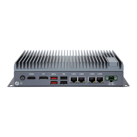
2 . E x t e r n a l I / O P o r t a n d O v e r v i e w Front I/O Ports Rear I/O Port Left I/O Ports Right I/O Ports items Items... -
Page 13: Power On/Off Button
Power ON/OFF HDMI 2 x U S B 3 . 2 G e n . 2 2 x USB2.0 DC-IN Audio USB 2.0 RS485/422/232 Remote ON/OFF Antenna Hole 2 x DB9 Service Doors SIM slot 2 . 1 P o w e r O N / O F F B u t t o n Define Status Green OFF:Power OFF... -
Page 14: Lan Ports
Theory Name Voltage/Current version Bandwidth (Max.) USB 2.0 480Mbps High-Speed 5V/500mA USB 3.2 10Gbps Super-Speed USB 5V / 900mA Gen2 2 . 4 L A N p o r t s 4x LAN ports, one Intel i210 GbE & three Intel i226-V 2.5GbE, support Wake on LAN, Intel i210 support EtherCAT 2 . -
Page 15: Serial Ports
i-Phone version Note: The microphone and GND of the Android version are opposite to those of the iPhone version, and cannot be shared. 2 . 8 S e r i a l p o r t s 6 x COM ports,4 x DB9 type,support 50~115.2kbps baud rate COM(1~4)RS485/422/232 ports pins RS232 pin define... -
Page 16: 4G/5G Antenna Reserved Hole
Note: 1. COM(1-4)support RS485/422/232 auto-flow, mode selection set by BIOS setting 2. COM(5-6)only support RS232 mode 2 . 9 3 G / 4 G / 5 G A n t e n n a r e s e r v e d h o l e 2 . -
Page 17: Sim Slot
3 . I n t e r n a l P i n H e a d e r a n d O v e r v i e w Main board Name PCB print name Mini-PCIe socket MINI_PCIE1 Clear CMOS jumper JCMOS1 battery connector JBAT1... -
Page 18: Mini-Pcie Socket
Mainboard Bottom 3 . 1 M i n i - P C I e S o c k e t MINI-PCIe Socket Mini-PCIe support PCIe/ USB2.0//mSATA signal supported 3 . 2 8 b i t i n t e r n a l G P I O p i n h e a d e r JGPIO1 pin header signal signal... -
Page 19: At/Atx Jumper
JGPSET1 jumper Printing name jumper Voltage 1-2(default) JGPSET1 3.3V 3 . 4 A T / A T X j u m p e r AT mode: the system starts automatically after power on ATX mode,The system starts by Power Button AT/ATX mode jumper setting refer to the following table AT_ATX1 jumper Printing name... -
Page 20: Installation
4 . I n s t a l l a t i o n 4 . 1 B o t t o m C o v e r / T o p c o v e r I n s t a l l a t i o n a n d R e m o v a l 1. -
Page 21: Key Parts Installation And Removal
2. Remove the 2 M3x6 spring screws in the middle of the motherboard and the 4 M3x4 screws in the four corners of the chassis, and remove the top cover (aluminum extrusion); as shown in 4.1-1-2 4.1-1-2 4 . 2 K e y P a r t s I n s t a l l a t i o n a n d R e m o v a l 1. - Page 22 M.2 2242 module: remove 1 pan-head M3x3 screw, as shown in 4.2-1; 4.2-1 emove the Mini-PCIE module: remove 1 flat-head M2x3 screw; Remove the 3052-5G module: remove 1 pan-head M3x3 screw to lock; as shown in 4.2-2. 4.2-2...
- Page 23 3. Attach the CPU PAD to the CPU chip or remove it from the CPU chip; as shown in 4.2-3 4.2-3 CPU PAD remove and install 4. Apply the memory thermal PAD and M2 thermal PAD to the anode; buckle the chassis module onto the aluminum extrusion;...
-
Page 24: Sim Card Installation And Removal
4 . 3 S I M c a r d I n s t a l l a t i o n a n d R e m o v a l 1.Remove the two M3*4 screws and remove the bracket; 2. -
Page 25: Bios Setup Setting
5 . B I O S s e t u p s e t t i n g 5 . 1 B I O S H o t - K e y Hot-Key Definition Description <DEL> Enter the BIOS After the system is powered on Setup interface <F7>... -
Page 26: Set System Time & Date
5 . 2 . 1 S e t s y s t e m T i m e & D a t e The Main menu features the settings of System Date and System Time and displays some BIOS info. 5 . -
Page 27: Turbo Mode Setting
Use the keyboard arrow keys to move to the BIOS Advanced option. The submenu has detailed option descriptions. 、 5 . 3 . 1 T u r b o M o d e s e t t i n g Enter the Advanced interface and select CPU Configuration->CPU-Power Management Control. -
Page 28: Com Mode Setting
5 . 3 . 2 C O M m o d e s e t t i n g Under the Advanced menu, select "IT8786 Super IO Configuration" -> "Serial Port X Configuration" -> "COM Mode Select". Users can select RS232, RS422 and RS485 for COM mode setting. -
Page 30: Chipset
5 . 4 C h i p s e t Use the keyboard arrow keys to move to the Chipset option. The submenu has detailed option descriptions. -
Page 31: Auto Turn-On (At/Atx)
5 . 5 A u t o T U R N - O N ( A T / A T X ) Enter "Chipset" menu, and select "Chipset"->"PCH-IO Configuration"->"State After G3" in order. Users can select "S0 State/S5 State" for power mode on the system. "S0 State"... -
Page 32: Security
5 . 7 S e c u r i t y Use the keyboard arrow keys to move to the Security option. The submenu has detailed option descriptions, including security settings. Administrator and user passwords can be set to protect the computer from infringement. -
Page 33: Set Administration Password And User Password
5.8 set Administration Password and User Password To set up Administrator password: Select Administrator Password. A Create New Password dialog then pops up onscreen. Enter your desired password that is no less than 3 characters and no more than 20 characters. Hit [Enter] key to submit. -
Page 34: Save & Exit
2. Quiet Boot: Select "Enable" to display the logo screen at startup. Select "Disable" to turn off the startup logo. 3. Boot Option Priorities: Set the system boot priorities. Enter Boot menu. In "Boot Option Priorities", users can set the order of boot devices. - Page 35 Dodavatelem tohoto produktu jsou FCC průmyslové systémy s. r. o. Informace o cenách, dostupnosti a dalších naleznete v našem e-shopu nebo se v případě jakéhokoliv dotazu obraťe přímo na nás. FCC průmyslové systémy s.r.o. U Výstaviště 138/3, Holešovice, 170 00 Praha 7 +420 472 774 173 info@fccps.cz www.fccps.cz...
Need help?
Do you have a question about the SB-244-1N97 and is the answer not in the manual?
Questions and answers