
Subscribe to Our Youtube Channel
Related Manuals for Arbor Technology Rigid-770 Series


Summary of Contents for Arbor Technology Rigid-770 Series
- Page 1 Rigid-770 Series Extreme Rugged Box Computer with Intel ® Core i3-3120ME / i5-3610ME ™ User’s Manual Version 1.1 2013.05 P/N: 4016077000110P...
- Page 2 This page is intentionally left blank. - 2 -...
- Page 3 Revision History Version Release Time Description 2013 February The initial release for Rigid-772. 2013 May Rigid-770 is included in the user's manual. The changes involved are: • 1.1. The Product • 1.3. Specifications • 1.4. Inside the Package • 1.5. Ordering Information •...
-
Page 4: Table Of Contents
Contents Revision History ................i Preface.................... v Copyright Notice.................. v Declaration of Conformity..............v CE ....................v FCC Class A ................v RoHS ...................vi SVHC / REACH ................vi Important Safety Instructions .............vii Warning .....................viii Replacing Lithium Battery ..............viii Technical Support................viii Warranty ....................ix Chapter 1 - Introduction .............. - Page 5 Contents 4.1.8. Install/uninstall CFast Card ..........71 4.1.9. Install/uninstall SIM Card ..........73 4.2. Mount the Computer ..............75 4.3. Ground the Computer ..............76 4.4. Wire DC-in Power Source ............77 Chapter 5 - BIOS ................79 5.1. Main ................... 82 5.2.
- Page 6 This page is intentionally left blank. - iv -...
-
Page 7: Preface
Preface Preface Copyright Notice All Rights Reserved. The information in this document is subject to change without prior notice in order to improve the reliability, design and function. It does not represent a commitment on the part of the manufacturer. Under no circumstances will the manufacturer be liable for any direct, indirect, special, incidental, or consequential damages arising from the use or inability to use the product or documentation, even if advised of the possibility of such... -
Page 8: Rohs
(PBDE) in electrical and electronic products. Member states of the EU are to enforce by 7/1/2006. ARBOR Technology Corp. hereby states that the listed products do not contain unintentional additions of lead, mercury, hex chrome, PBB or PBDB that exceed a maximum concentration value of 0.1% by weight or for cadmium exceed... -
Page 9: Important Safety Instructions
Preface Important Safety Instructions Read these safety instructions carefully Read all cautions and warnings on the equipment. Place this equipment on a reliable surface when installing. Dropping it or letting it fall may cause damage Make sure the correct voltage is connected to the equipment. For pluggable equipment, the socket outlet should be near the equipment and should be easily accessible. -
Page 10: Warning
Preface Warning The Box PC and its components contain very delicately Integrated Circuits (IC). To protect the Box PC and its components against damage caused by static electricity, you should always follow the precautions below when handling it: Disconnect your Box PC from the power source when you want to work on the inside. -
Page 11: Warranty
Preface Warranty This product is warranted to be in good working order for a period of one year from the date of purchase. Should this product fail to be in good working order at any time during this period, we will, at our option, replace or repair it at no additional charge except as set forth in the following terms. - Page 12 This page is intentionally left blank. - x -...
-
Page 13: Chapter 1 - Introduction
Chapter 1 Introduction Chapter 1 - Introduction - 1 -... -
Page 14: The Product
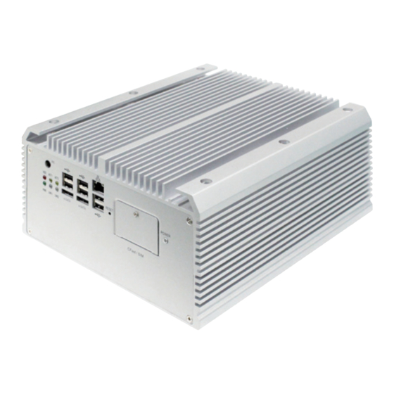
Introduction 1.1. The Product The computer is ARBOR’s new generation of extreme rugged box system based on Intel ® Core i3-3120ME / i5-3610ME with chipset ™ Intel QM77 to deliver low power consumption, ® high performance and wide temperature tolerance Integrated with Intel HD 4000 graphics, the ®... -
Page 15: Specifications
Introduction 1.3. Specifications System Kernel Intel Core i3-3120ME (by default) ® ™ Processor Intel Core i5-3610ME (dual-core) (rPGA988B) (by OEM request) ® ™ BIOS AMI Flash BIOS Chipset Intel QM77 ® Graphics Integrated Intel HD 4000 ® 2 x 204-pin DDR3 SO-DIMM sockets supporting up to 16GB at 1333/1600 MHz System Memory 4GB wide-temperature DDR3 memory module installed (as... - Page 16 Introduction Storage 2 x 2.5” drive bays Type 1 x CFast slot Qualification Certification CE, FCC Class A Environment Operating Temp. -40 ~ 70°C (-40 ~ 158°F), ambience w/ air flow Storage Temp. -40 ~ 85°C (-40 ~ 185°F) Operating Humidity 10 ~ 95% @ 70°C (non-condensing) Vibration 3 Grms/5 ~ 500Hz/random operation w/ SSD Operating 20G (11ms);...
-
Page 17: Inside The Package
Upon opening the package, carefully inspect the contents. If any of the items is missing or appears damaged, contact your local dealer or distributor. The package should contain the following items: 1 x Rigid-770 Series Extreme Rugged Box System 1 x Driver CD 1 x User’s Manual... -
Page 18: Ordering Information
Introduction 1.5. Ordering Information Rigid-770 Fanless embedded controller Rigid-772 Fanless embedded controller, w/ PCIe x16 slot and PCIe x8 slot 1.5.1. Configure-to-Order Service Make the computer more tailored to your needs by selecting one or more components from the list below to be fabricated to the computer. SSD-25040 Intel 2.5”... -
Page 19: Chapter 2 - Getting Started
Chapter 2 Getting Started Chapter 2 - Getting Started - 7 -... -
Page 20: System Overview
Getting Started 2.1. System Overview This section will give an overview of the computer. 2.1.1. Dimensions The following illustration shows the dimensions of the computer, with the measurements in width, depth, and height called out. Rigid-770 6.00 NUT UNC#6-32 238.00 250.00 225.00 Unit: mm... - Page 21 Gettting Started Rigid-77x 6.00 NUT UNC#6-32 238.00 250.00 225.00 Unit: mm - 9 -...
-
Page 22: Take A Tour
Getting Started 2.1.2. Take A Tour The computer has some I/O ports, status LED lights and controls on the front and rear panels. The following illustrations show all the components called out. 2.1.2.1. Front View Rigid-770 ⑤ ③ ① ② ④... - Page 23 Rigid-77x ⑤ ③ ① ② ④ ⑭ ⑬ ⑥ ⑫ ⑩ ⑪ ⑨ ⑧ ⑦ Description Description ① ⑧ LAN1 Active LED USB 2.0 ports ② ⑨ LAN2 Active LED eSATA ports ③ ⑩ USB 2.0 ports LAN2 Link LED ④...
- Page 24 Getting Started 2.1.2.2. Rear View Take a look a the rear side of the computer. Rigid-770 Line out DIO/LPT LAN ports DVI-I Mic in (Selectable) COM Ports DVI-D USB 3.0 DC-in ports Rigid-77x Line out DIO/LPT LAN ports DVI-I Mic in (Selectable) USB 3.0 ports COM Ports 1~4...
- Page 25 Gettting Started 2.1.2.3. Side Views Rigid-770 Rigid-77x - 13 -...
- Page 26 Getting Started Rigid-770 Rigid-77x - 14 -...
-
Page 27: Driver Installation Notes
Gettting Started 2.2. Driver Installation Notes The computer supports the operating systems of Windows XP, Windows 7 and Linux. For Windows O.S., find the necessary device drivers on the CD that comes with your purchase. For different O.S., the installation of drivers/utilities may vary slightly, but generally they are similar. - Page 28 Getting Started Windows 7 Driver Path Chipset INF\Intel Chipset Software Installation Utility Graphic driver\WIN7\Graphic_win7_64_V8.15.10.2795 Graphic driver\WIN7\Intel HD Graphics Driver - 32 Bit LAN\XP_WIN7_SERIES\32 LAN\XP_WIN7_SERIES\64 Audio AUDIO\WIN7 USB 3.0\Intel_USB_3.0_xHC_Driver_ENG_1.0.4.225\Intel(R) USB 3.0 USB 3.0 eXtensible Host Controller Driver ENG 1.0.4.225\ Driver_Installer Intel® Management ME\ME Engine...
-
Page 29: Chapter 3 - System Configuration
Chapter 3 System Configuration Chapter 3 - System Configuration - 17 -... -
Page 30: Board Layout
Engine of the Computer 3.1. Board Layout The main board FMB-i77M1 forms the engine of the computer. This section will give an thorough view of this board. FMB-i77M1: Board Top 51 52 - 18 -... - Page 31 Engine of the Computer FMB-i77M1: Board Bottom - 19 -...
-
Page 32: Jumpers, Connectors And Dip Switches
Engine of the Computer 3.2. Jumpers, Connectors and DIP Switches The main board FMB-i77M1 comes with some connectors to join cables to other devices and some jumpers and DIP switches to alter hardware configuration. The following in this chapter will explicate each of the components one-by-one. 3.2.1. Jumpers JBAT1 Board Top Function: CMOS Setting Jumper Type: Onboard 2.54mm pitch 1x3-pin header... - Page 33 Engine of the Computer JME1 Board Top Function: Enables/disables Intel Management ® Engine Jumper Type: Onboard 2.00mm pitch 1x3-pin header Setting: Description Setting Enables ME (default) Disables ME 51 52 - 21 -...
- Page 34 Engine of the Computer Board Top Function: Controls power supply mode Jumper Type: Onboard 2.54mm pitch 1x3-pin header Setting: Description Setting Sets power supply to AT mode Sets power supply to ATX mode (default) Note this setting should be consistent with BIOS | 51 52 Advanced | ACPI Settings | Power-Supply Type to...
- Page 35 Engine of the Computer JPIC1 Description: External PIC programming pin header Jumper Type: Onboard 2.00mm pitch 3x2-pin header Description ICSP-CLK ICSP-DAT VCC5_PIC MCU_RST 51 52 LPCI1 Function: Board debugging Jumper Type: Onboard 2.00mm pitch 2x5-pin header Description PCLK_FWH LFRAME# LAD0 BUF_ PLTRST_N LAD3...
-
Page 36: Dip Switch Sw9
Engine of the Computer 3.2.2. DIP Switch SW9 The computer comes with a DB44 female connector for COM ports 1~4. COM1 and COM2 are fixed to RS232 while COM3 and COM4 can be switched between loopback, RS232, RS485 half-duplex and RS485/RS422 full-duplex. The main board is provided with a 8-toggle (16-pin) DIP switch on the top side to switch COM3 and COM4 among the available protocols Board Top Among the toggles: Toggles 1, 2... - Page 37 Engine of the Computer Signal Control High Toggle Position Position Toggle Toggle Follow the guide below to switch COM3 and COM4 between loop-back, RS232, RS485 Half-Duplex and RS485/422 Full Duplex. Note the DIP switch setting here needs to be consistent with BIOS | Advanced Menu | F81866 Second Super IO Configuration | Serial Port 3 Configuration and Serial Port 4 Configuration to prevent possible conflict. See 5.2.7.
- Page 38 Engine of the Computer COM3 Toggle Position Setting RS232 not applicable not applicable not applicable not applicable Toggle not applicable COM3 Toggle Position Setting RS485 Half-Duplex not applicable not applicable not applicable not applicable Toggle not applicable Note this setting should be consistent with BIOS | Advanced menu | F81866 Second Super IO Configuration | Serial Port 3 Configuration to prevent conflict. See Serial Port 3 Configuration on page 91.
- Page 39 Engine of the Computer • COM4 Settings COM4 Toggle Position Setting not applicable Loop-back not applicable not applicable not applicable Toggle not applicable COM4 Toggle Position Setting not applicable RS232 not applicable not applicable not applicable Toggle not applicable COM4 Toggle Position Setting...
- Page 40 Engine of the Computer COM4 Toggle Position Setting not applicable RS485/RS422 not applicable Full-Duplex not applicable not applicable Toggle not applicable Note this setting should be consistent with BIOS | Advanced menu | F81866 Second Super IO Configuration | Serial Port 4 Configuration to prevent conflict. See Serial Port 4 Configuration on page 91.
-
Page 41: Connectors
Engine of the Computer 3.2.3. Connectors SATA1 & SATA2 Description: Serial ATA connectors for storage devices Connector Type: 7-pin Serial ATA connector Description Board Bottom - 29 -... - Page 42 Engine of the Computer PWROUT1 and PWROUT2 Description: Power connectors for SATA storage devices Connector Type: 2.54mm-pitch 1x4-pin DIP-type connector Pin Desc. VCC5 +12V Board Bottom - 30 -...
- Page 43 Engine of the Computer Description: PCI Express MiniCard socket Connector Type: Onboard 0.8mm pitch 52-pin edge card connector Pin Desc. Pin Desc. Pin Desc. Wake 20 W_Disable# 36 USB_D- +3.3V 21 GND 37 GND COEX1 22 PERST# 38 USB_D+ 23 PERn0 39 +3.3V COEX2 24 +3.3V...
- Page 44 Engine of the Computer DIO1 Description: Digital I/O connector Connector Type: Onboard 2.00mm pitch 2x13-pin box header Pin Desc. Pin Desc. DIO0 DIO1 DIO2 DIO3 DIO4 DIO5 DIO6 DIO7 DIO8 DIO9 DIO10 DIO11 DIO12 DIO13 DIO14 DIO15 VCC5 VCC5 Board Top Rear Panel - 32 -...
- Page 45 Engine of the Computer LPT1 Description: Printer/parallel port connector Connector Type: Onboard 2.00mm pitch 2x13-pin box header Pin Desc. Pin Desc. XP_STB# P_AFD# XP_D0 P_ERR# XP_D1 P_INIT# XP_D2 P_SLIN# XP_D3 XP_D4 XP_D5 XP_D6 XP_D7 P_ACK# P_BUSY P_PE P_SLCT Board Top Rear Panel - 33 -...
- Page 46 Engine of the Computer PWRIN1 Description: DC-in power receptacle 1 2 3 4 Connector Type: 5.00mm-pitch 4-pole Euro-Type terminal block Pin Desc. PWRINV+ PWRINV- G-GND PWR_IN_SW# Board Top 51 52 Rear Panel - 34 -...
- Page 47 Engine of the Computer DVI Connectors The computer features two DVI (digital visual interface) ports, supporting both DVI-I (digital and analog) and DVI-D (analog only). • DVI-I Description: DVI-I port (digital and C1 C2 analog) Connector Type: 29-pin DIP-type female connector C4 C3 Pin Desc.
- Page 48 Engine of the Computer • DVI-D Description: DVI-D port (analog only) Connector Type: 24-pin DIP-type female connector Pin Desc. Pin Desc. Pin Desc. T.M.D.S DATA 2- T.M.D.S DATA 1/3 SHIELD T.M.D.S DATA 5+ T.M.D.S DATA 2+ T.M.D.S DATA 3- T.M.D.S CLOCK SHIELD T.M.D.S DATA 2/4 SHIELD T.M.D.S DATA 3+ T.M.D.S CLOCK+...
- Page 49 Engine of the Computer Audio1 Description: Audio connector Connector Type: 2.54mm-pitch 4-wall 1x6-pin wafer connector Pin Desc. MICL MICR MIC GND Speaker(Lout)-L Speaker(Lout)-R Speaker GND Board Top 51 52 Rear Panel - 37 -...
- Page 50 Engine of the Computer LAN1 Description: One Ethernet port over double- stacked USB 2.0 ports Connector Type: One 8P8C RJ45 connector w/ two type-A USB connectors LAN (RJ-45) USB (Type-A) 1 2 3 4 Pin Desc. Pin Desc. Pin Desc. 1 MDI0+ MDI2+ 1 2 3 4...
- Page 51 Engine of the Computer LAN2 and LAN3 Description: One Ethernet port over double- stacked USB 3.0/2.0 ports Connector Type: One 8P8C RJ45 connector w/ two SuperSpeed type-A USB 3.0/2.0 connectors 1 2 3 4 LAN (RJ-45) USB (Type-A) Pin Desc. Pin Desc.
- Page 52 Engine of the Computer USB2 Description: Double-stacked USB 2.0 ports over one eSATA port 1 2 3 4 Pin Desc. Desc. USB01_VCC USB01_VCC 1 2 3 4 USBP_10N_CON USBP_11N_CON USBP_10P_CON USBP_11P_CON USB_GND USB_GND USB_GND USB_GND USB_GND USB_GND USB_GND SATA_TXP4 SATA_TXN4 USB_GND SATA_RXN4 SATA_RXP4...
- Page 53 Engine of the Computer USB3 Description: Double-stacked USB 2.0 ports over one eSATA port 1 2 3 4 Pin Desc. Desc. USB23_VCC USB23_VCC 1 2 3 4 USBP_12N_CON USBP_13N_CON USBP_12P_CON USBP_13P_CON USB_GND USB_GND USB_GND USB_GND USB_GND USB_GND USB_GND SATA_TXP5 SATA_TXN5 USB_GND SATA_RXN5 SATA_RXP5...
- Page 54 Engine of the Computer USB1 and USB4 Description: Connectors for the internal USB USB4 USB1 ports (Configure-to-Order) Connector Type: Type A female USB 2.0 ports compatible USB1 USB4 Pin Desc. Desc. USBP_4N_CON USBP_5N_CON USBP_4P_CON USBP_5P_CON Board Bottom - 42 -...
- Page 55 Engine of the Computer CN1: Description: COM1~4 (COM1/2 are RS232; COM3/4 are RS232/422/485 selectable) Connector type: DB44 female connector Desc. Desc. Desc. Desc. COM1 COM2 GND2 GND2 (RS-232) (RS-232) GND1 GND1 RS232 RS422 RS485 RS232 RS422 RS485 Desc. Desc. Desc. Desc.
- Page 56 This page is intentionally left blank. - 44 -...
-
Page 57: Chapter 4 - Installation And Maintenance
Chapter 4 Installation and Maintenance Chapter 4 - Installation and Maintenance - 45 -... -
Page 58: Install Hardware
Installation & Maintenance 4.1. Install Hardware The computer is constructed based on modular design to make it easy for users to add hardware or to maintain the computer. The following sections will guide you to the simple hardware installations for the computer. 4.1.1. - Page 59 Installation & Maintenance From the front panel, loosen and remove the 2 screws as marked in the illustrations below. (And make sure the CF card door is closed.) Rigid-770 Front Rigid-772 Front From the rear panel, loosen and remove the 2 screws as marked in the illustrations below.
- Page 60 Installation & Maintenance To adjust jumpers or connect/disconnect cables to/from the main board, 3.2. Jumpers, Connectors and DIP Switches on page 20. To install memory modules, see 4.1.2. Install/uninstall Memory Modules on page on page 4.1.3. Install Memory Module with Heat Spreaders To install MiniCard-based wireless modules, see 4.1.4.
- Page 61 Installation & Maintenance 4.1.1.2. Remove Bottom Cover The Serial ATA connectors, the power connectors for SATA storage devices, and the internal USB ports (configure-to-order), PCI and PCIe connectors are all built on the bottom side of the maind board. To access these connectors, the computer’s bottom cover has to go. Follow through the steps below to remove the bottom cover from the computer.
- Page 62 Installation & Maintenance From the rear panel, loosen and remove the 2 screws as marked in the illustrations below. Rigid-770 Rear Rigid-772 Rear After the said screws are removed, proceed to dismount the bottom cover. Carefully pry at the joint of the bottom cover and top cover, which locates at about two third of the computer’s height for Rigid-772 and about four fifth of the computer for Rigid-770. Then completely part the bottom cover from the computer.
- Page 63 Installation & Maintenance To install internal USB drives, see on page 4.1.5. Install Internal USB Drives To install SATA storage devices, see 4.1.6. Install SATA Storage Devices page 64. To install PCI/PCIe cards, see on page 70. 4.1.7. Install PCI Express Cards - 51 -...
-
Page 64: Install/Uninstall Memory Modules
Installation & Maintenance 4.1.2. Install/uninstall Memory Modules The main board has two dual inline memory module (DIMM) sockets. Increase memory capacity to make programs run faster on the system. The memory module for the computer's SO-DIMM sockets should be a 204-pin DDR3 with a “key notch”... - Page 65 Installation & Maintenance Pull back both latches from the socket. the break latch latch the SO-DIMM socket’s slot connector vertical-type SO-DIMM socket (overview) Confront the memory module’s edge connector side at the SO-DIMM socket. Position the memory module at the SO-DIMM socket, with the memory module’s key notch aligned at the break of the SO-DIMM’s slot connector.
-
Page 66: Install Memory Module With Heat Spreaders
Installation & Maintenance 4.1.3. Install Memory Module with Heat Spreaders Have the heat spreaders. One has the bigger fin and the other has the smaller fin. Each heat spreader comes with a thermal pad. Attach the memory module to the thermal pad side of the heat spreader with bigger fin. See the picture below. The connector break on the 204-pin memory module Attach the memory module to the thermal pad... - Page 67 Installation & Maintenance View from the other side.. Attach the other heat spreader to the other side of the memory module so the two heat spreaders sandwich the memory module. Be sure to align the two heat spreaders properly so as to form the two clip holes. - 55 -...
- Page 68 Installation & Maintenance Have the two metal clips. Use them to hold the heat spreaders and the memory module together. - 56 -...
- Page 69 Installation & Maintenance Make sure the heat spreaders are clipped exactly as shown in the pictures below. Fully push the clips until they cannot be pushed any more. See the pictures below. push - 57 -...
- Page 70 Installation & Maintenance Note: The above mentioned demonstrated one clip only. When you install the memory module with heat spreaders, be sure to use both clips. Remove the top cover from the computer as described in 4.1.1.1. Remove Top Cover on page 46.
- Page 71 Installation & Maintenance 10. Vertically plug the memory module to the DIMM socket. “Fully” plug the memory module until both latches auto-lock the memory module in place. key notch 11. Attach another thermal pad onto the top of the heat spreaders. Thermal pad 12.
-
Page 72: Install Minicards
Installation & Maintenance 4.1.4. Install MiniCards Remove the top cover from the computer as described in 4.1.1.1. Remove Top Cover on page Find the MiniCard socket on the board as marked in the illustration below. The MiniCard socket’s connector has a break. connector break MiniCard... - Page 73 Installation & Maintenance Press down the module and fix it in place using two screws. Remove the plastic plug from the enclosure’s front panel to make an antenna hole. Keep the plastic plug for any possible restoration in the future. Have an RF cable. Connect the RF cable to the mini-card socket’s “MAIN” connector.
- Page 74 Installation & Maintenance Pull the other end of the RF cable, a SMA connector jack, through the antenna hole. Be sure to meet the flat side of the antenna hole so the connector jack won’t get stuck. the flat side of the antenna hole Mount a round washer on the SMA connector jack from outside the chassis, and secure an nut to it.
-
Page 75: Install Internal Usb Drives
Installation & Maintenance 4.1.5. Install Internal USB Drives Since some critical application programs rely on a USB key to run, an USB drive is necessary to store related encrypted keys and digital certificates. The computer allows building two USB ports inside the chassis to support two USB drives to work therein for reinforced protection against theft or tamper. (Configure-to-Order only) To install the internal USB drive(s): Remove the bottom cover from the computer as described in... -
Page 76: Install Sata Storage Devices
Installation & Maintenance 4.1.6. Install SATA Storage Devices The computer supports two 2.5” SATA storage devices to work inside the computer for RAID. The following will guide you to install two SATA HDD or SSD. 4.1.6.1. Install SATA Storage Devices to Rigid-770 Remove the bottom cover from the computer as described in 4.1.1.2. - Page 77 Installation & Maintenance Fix the storage device in place by using screws at the four screw holes on both sides of the bracket. Install the bracket and the storage device back into the computer by refastening the four screws. SATA connectors power connectors for SATA storage...
- Page 78 Installation & Maintenance Install the bracket and the storage device back into the computer by refastening the three screws. SATA connectors power connectors for SATA storage devices Restore the bottom cover to the computer. - 66 -...
- Page 79 Installation & Maintenance 4.1.6.2. Install SATA Storage Devices to Rigid-772 Remove the bottom cover from the computer as described in 4.1.1.2. Remove Bottom Cover on page 49. Find the HDD/SSD bracket inside the computer. Loosen and remove the four screws as marked in the picture below. Then dismount the bracket from the computer.
- Page 80 Installation & Maintenance Slide another HDD/SSD storage device into the bracket. Fix another storage device in place by using screws at the four screw holes on both sides of the bracket. the bracket and two 2.5” SATA storage devices piggybacking. Reinstall the bracket (with the storage devices) to the computer.
- Page 81 Installation & Maintenance Connect the SATA signal cable(s) and power cable(s). Restore the bottom cover to the computer. - 69 -...
-
Page 82: Install Pci Express Cards
Installation & Maintenance 4.1.7. Install PCI Express Cards For computer buses, the computer features each PCIe x16 slot and PCIe x8 slot. Follow the guide below to install an PCI Express card to the computer. To install a PCI Express card: Remove the bottom cover from the computer as described in 4.1.1.2. -
Page 83: Install/Uninstall Cfast Card
Installation & Maintenance Plug the PCI Express card to the due slot. Re-fasten the screw to fix the card in place. Restore the bottom cover to the computer. 4.1.8. Install/uninstall CFast Card The computer supports a CFast card for storage and comes with an outside- accessible CFast slot. Follow through the guide below to install a CFast card to the computer. - Page 84 Installation & Maintenance Once the screw is removed, open the door. The CFast slot then comes to view. CFast slot Follow the printed graphic to install the CFast card The door is a hinged door. On the inner side of the door, there is a printed graphic to guide users of the direction to insert the CFast card.
-
Page 85: Install/Uninstall Sim Card
Installation & Maintenance 4.1.9. Install/uninstall SIM Card The computer supports a SIM card for mobile networking and comes with an outside-accessible SIM card slot. Follow through the guide below to install a SIM card to the computer. To install the SIM card: From the front panel of the computer, find the door to the SIM card slot. - Page 86 Installation & Maintenance To uninstall the SIM card: Loosen and remove the card door screw and open the card door. Push-eject the SIM card. Remove the SIM card. Refasten the screw to close the card door. Note to refasten the screw to close the card door each time the SIM card is installed or uninstalled.
-
Page 87: Mount The Computer
4.2. Mount the Computer Integrate the computer to where it works by mounting it to a wall in the surroundings. Such integration relies on a wall-mount kit, which comes with the computer. Follow through the guide below to assemble the kit to the computer: Place the computer on a flat surface, with the bottom facing up. Find the eight screw holes at its bottom as marked in the red circles in the illustration below:... -
Page 88: Ground The Computer
4.3. Ground the Computer Follow the instructions below to ground the computer to land. Be sure to follow every grounding requirement in your place. Warning Whenever the unit is installed, the ground connection must always be made first of all and disconnected lastly. See the illustration below. Remove the ground screw from the rear panel. Attach a ground wire to the rear panel with the screw. -
Page 89: Wire Dc-In Power Source
4.4. Wire DC-in Power Source Warning Only trained and qualified personnel are allowed to install or replace this equipment. Follow the instructions below for connecting the computer to a DC-input power source. Before wiring, make sure the power source is disconnected. Find the terminal block in the accessory box. Use the wire-stripping tool to strip a short insulation segment from the output wires of the DC power source. - Page 90 This page is intentionally left blank. - 78 -...
-
Page 91: Chapter 5 - Bios
Chapter 5 BIOS Chapter 5 - BIOS - 79 -... - Page 92 BIOS The BIOS Setup utility for the computer is featured by American Megatrends Inc to configure the system settings stored in the system’s BIOS ROM. The BIOS is activated once the computer powers on. When the computer is off, the battery on the main board supplies power to BIOS RAM. To enter the BIOS Setup utility, keep hitting the “Delete” key upon powering on the computer.
- Page 93 BIOS Key Commands The BIOS Setup utility relies on a keyboard to receive user’s instructions. Hit the following keys to navigate within the utility and use the utility. Keystroke Function ← → Moves left/right between the top menus. ↓ ↑ Moves up/down between highlight items.
-
Page 94: Main
BIOS 5.1. Main The Main menu features the settings of System Date and System Time and displays some BIOS info. Aptio Setup Utility - Copyright (C) 2011 American Megatrends, Inc. Main Advanced Chipset Boot Security Save & Exit BIOS Information Choose the system default BIOS Vendor American Megatrends... -
Page 95: Advanced
BIOS 5.2. Advanced Access the Advanced menu to manage the computer’s system configuration including the Super IO chip, Fintek 81866. Aptio Setup Utility - Copyright (C) 2011 American Megatrends, Inc. Main Advanced Chipset Boot Security Save & Exit ACPI Settings System ACPI Parameters SS RTC Wake Setting CPU Configuration SATA Configuration AMT Configuration... -
Page 96: Acpi Settings
BIOS 5.2.1. ACPI Settings The submenu ACPI Settings enable users to change the system’s ACPI (Advanced Configuration and Power Interface) configuration by the following settings: Setting Description Enables/disables the system to/from hibernation (OS/S4 Sleep State). Enable Hibernation This option may not be effective with some OS. Options available are Enabled (default) and Disabled. Sets the ACPI sleep state for the system to enter when the suspend button is hit. -
Page 97: Ss Rtc Wake Settings
BIOS 5.2.2. SS RTC Wake Settings Access this submenu to configure whether and when to awake the system. The featured settings are: Setting Description Sets if to awake the system at a defined moment. Options available are Enabled and Disabled (default). Enable this feature to awake the system at a defined moment in time. When enabled, the following settings become available: Setting Description Defines the (hour) time to awake the... -
Page 98: Cpu Configuration
BIOS 5.2.3. CPU Configuration Select CPU Configuration to run a report of the CPU's details including: model name, processor speed, microcode revision, max./min. processor speeds, the amount of processor core(s), Intel Hyper-Threading Technology support, Intel ® ® virtualization technology (VT-x) support, Intel Safer Mode Extensions (SMX) ®... -
Page 99: Sata Configuration
BIOS 5.2.4. SATA Configuration SATA Configuration manages the system’s SATA configuration and also delivers its status. The featured settings are: Setting Description Enables/disables SATA device(s). SATA Controller(s) Enabled is the default. Configures how to operate the SATA controller(s). SATA Mode Selection Options available are IDE, AHCI (default) and RAID. Defines the maximum speed the SATA controller can support. -
Page 100: Amt Configuration
BIOS 5.2.5. AMT Configuration Intel Active Management Technology (Intel AMT) is a hardware-based solution ® ® that uses out-of-band communication for system administrators to monitor and manage the computers and other network equipment by remote control even if the hard drive is crashed, the system is turned off or the operating system is locked. -
Page 101: Usb Configuration
BIOS 5.2.6. USB Configuration Select this submenu to view the status of the USB devices and configure USB features. The featured settings are: Setting Description Enables/disables legacy USB support. Options available are Enabled (default), Disabled and Auto. Legacy USB Support Select Auto to disable legacy support if no USB device are connected. Select Disabled to keep USB devices available only for EFI applications. -
Page 102: F81866 Super Io Configuration
BIOS 5.2.7. F81866 Super IO Configuration This submenu configures the Super IO chip (Fintek F81866) for the computer’s serial ports 1~4 and the parallel port. The featured submenus are: Submenu Description Configures the computer’s COM1, which is fixed to RS232 and cannot be changed. The featured settings are: Setting Description Enables/disables the serial port. Serial Port Enabled is the default. - Page 103 BIOS Configures the computer’s COM3, which is configurable between RS232, RS422 and RS485. The featured settings are: Setting Description Enables/disables the serial port. Serial Port Enabled is the default. Sets the optimal IO address and IRQ info for the serial port. Options available are: IO=3E8h;...
- Page 104 BIOS Configures the computer’s parallel port (printer port). The featured settings are: Setting Description Enables/disables the parallel port. Parallel Port Enabled is the default. Sets the optimal IO address and IRQ info for the parallel port Options available are: IO=378h; IRQ=7; (default) IO=378h; IRQ=5,7; IO=278h; IRQ=5,7; Change When the Device Mode (see the next Settings setting) is set to ECP Mode, ECP &...
-
Page 105: F81866 H/W Monitor
BIOS 5.2.8. F81866 H/W Monitor Select this submenu to view the main board’s hardware status. Select it to run a report of various info as depicted below: Aptio Setup Utility - Copyright (C) 2011 American Megatrends, Inc. Main Advanced Chipset Boot Security Save & Exit PC Health Status CPU temperature : +34%... -
Page 106: Chipset
BIOS 5.3. Chipset The Chipset menu controls the system’s chipset. Aptio Setup Utility - Copyright (C) 2011 American Megatrends, Inc. Main Advanced Chipset Boot Security Save & Exit PCH-IO Configuration PCH Parameters System Agent (SA) Configuration →←: Select Screen : Select Item Enter: Select +/-: Change Opt. -
Page 107: Pch-Io Configuration
BIOS 5.3.1. PCH-IO Configuration Select this submenu to view the RC version, SKU name and revision ID of the Intel PCH. Select this submenu also to configure the PCH: ® The featured settings/submenus are: Setting / Description Submenu Configures the computer’s USB (2.0) features by the following settings: Setting Description Configuration EHCI1 Control the USB EHCI (USB2.0) function. Both EHCI are enabled by default. -
Page 108: System Agent (Sa) Configuration
BIOS 5.3.2. System Agent (SA) Configuration Select this submenu to view the name and RC version of the System Agent (SA), i.e. the north bridge. Select this submenu also to configure the System Agent (SA) by the following setting and submenus: Setting / Description Submenu Enables/disables Intel virtualization technology for directed I/O on ®... - Page 109 BIOS Delivers the status and configures the north bridge PEG (PCI Express Graphics) by the following settings: Setting Description Configures PEG0 B0:D1:F0 Gen1-Gen3, or leaves it on BIOS auto-configuration. PEG - Gen X Options available are Auto, Gen1, Gen2 and Gen3 (default). Configures the ASPM (Active State Power Management) support for the PEG device, or leaves it on BIOS auto-configuration.
-
Page 110: Boot
BIOS 5.4. Boot The Boot menu configures how to boot up the system such as the configuration of boot device priority. Aptio Setup Utility - Copyright (C) 2011 American Megatrends, Inc. Main Advanced Chipset Boot Security Save & Exit Boot Configuration Number of seconds to wait for Setup Prompt Timeout setup activation key. Bootup NumLock State [On] 65535 (0xFFFF) means indefinite... - Page 111 BIOS Enables/disables initializing only a minimal set of devices required to launch the active boot options when booting up the system. Disabled is the default. This setting has no effect for BBS (BIOS Boot Specification) options. When enabled, the following settings become available: Setting Description...
-
Page 112: Csm Paramenters
BIOS 5.4.1. CSM Paramenters Access this submenu to configure the execution of OpROM, boot options filter and so on. The featured settings are: Setting Description Enables/disables launching CSM (capability support module), which provides UEFI with the additional functionality to allow Launch CSM loading a traditional OS or using a traditional OpROM. Options available are: Always (default) and Never. -
Page 113: Security
BIOS 5.5. Security The Security menu sets up the password for the system’s administrator account. Once the administrator password is set up, this BIOS Setup utility is limited to access and will ask for the password each time any access is attempted. -
Page 114: Save & Exit
BIOS 5.6. Save & Exit The Save & Exit menu features a handful of commands to launch actions from the BIOS Setup utility regarding saving changes, quitting the utility and recovering defaults. Aptio Setup Utility - Copyright (C) 2011 American Megatrends, Inc. Main Advanced Chipset Boot Security Save &... -
Page 115: Appendices
Appendices Appendices - 103 -... -
Page 116: A: Digital I/O Setting
Appendices A: Digital I/O Setting Digital I/O can read from or write to a line or an entire digital port, which is a collection of lines. This mechanism helps users achieve various applications such as industrial automation, customized circuit, and laboratory testing. Take the source code below that is written in C for the digital I/O application example. - Page 117 Appendices delay(10); /* GPIO20~27 Data */ SMB_Byte_WRITE(SMB_PORT_AD,SMB_DEVICE_ADD,0x21,(oData & 0xFF00) >> 8 ); delay(10); /* GPIO10~17 Status */ iTemp = SMB_Byte_READ(SMB_PORT_AD,SMB_DEVICE_ADD,0x12); iData = iTemp; delay(10); /* GPIO20~27 Status */ iTemp = SMB_Byte_READ(SMB_PORT_AD,SMB_DEVICE_ADD,0x22); iData = ( iTemp << 8 ) + iData; delay(10);...
-
Page 118: B: Watchdog Timer (Wdt) Setting
Appendices B: Watchdog Timer (WDT) Setting WDT is widely used for industry application to monitor the activity of CPU. Application software depends on its requirement to trigger WDT with adequate timer setting. Before WDT time out, the functional normal system will reload the WDT. - Page 119 This page is intentionally left blank. - 107 -...
Need help?
Do you have a question about the Rigid-770 Series and is the answer not in the manual?
Questions and answers