
Subscribe to Our Youtube Channel
Related Manuals for Arbor Technology FPC-7500 Series


Summary of Contents for Arbor Technology FPC-7500 Series
- Page 1 FPC-7500/ FPC-7502 Series Fanless Intel® Socket G Core™ i5/i7 Box PC User’s Manual Version 1.1 2014.11 P/N: 4012750000110P...
- Page 2 This page is intentionally left blank.
-
Page 3: Table Of Contents
Index Chapter 1 - General Information ..........1 1.1 Introduction ..............2 1.2 Packing List..............3 1.3 The Installation Paths of CD Driver......4 1.4 Specifications ............4 1.5 Power Information .............6 1.6 Dimensions ..............6 1.7 Locating Controls and Connectors ......7 1.8 Connecting Peripherals ..........9 1.8.1 VGA/DVI/DisplayPort Video Outputs.....9 1.8.2 Serial Ports (COM1 ~4) .........10 1.8.3 LAN Ports .............. - Page 4 Index AUDIO1 (Audio Jacks) ..........26 MC1 (PCIe Mini-card socket) ........27 CPUF1/2 (Fan Connector) ..........28 KBM1 (Keyboard & Mouse) .......... 28 CF1 (CFast Slot) ............28 DVI1 (DVI) ............... 30 JSPI1 (System BIOS Enable/ Disable Pin Header, factory use only) ............30 DIO1 (Digital I/O Port) ...........
- Page 5 Index 4.2.8 Second Super IO Configuration ......64 4.2.9 Platform Thermal Configuration ......65 4.3 Chipset Settings ............66 4.3.1 North Bridge ............67 4.3.2 South Bridge Configuration ........68 4.4 Boot Settings ............69 4.5 Security..............71 4.6 Save & Exit ...............73 Appendix .................76 Appendix A: I/O Port Address Map ......77 Appendix B: Interrupt Request Lines (IRQ) ....79 Appendix C: Memory Mapping ........80 Appendix D: Digital I/O Setting ........82...
- Page 6 This page is intentionally left blank. - IV -...
- Page 7 Copyright Notice All Rights Reserved. The information in this document is subject to change without prior notice in order to improve the reliability, design and function. It does not represent a commitment on the part of the manufacturer. Under no circumstances will the manufacturer be liable for any direct, indirect, special, incidental, or consequential damages arising from the use or inability to use the product or documentation, even if advised of the possibility of such damages.
- Page 8 RoHS ARBOR Technology Corp. certifies that all components in its products are in compliance and conform to the European Union’s Restriction of Use of Haz- ardous Substances in Electrical and Electronic Equipment (RoHS) Directive 2002/95/EC.
- Page 9 Important Safety Instructions Read these safety instructions carefully 1. Read all cautions and warnings on the equipment. 2. Place this equipment on a reliable surface when installing. Dropping it or letting it fall may cause damage 3. Make sure the correct voltage is connected to the equipment. 4.
- Page 10 About This User’s Manual This User’s Manual is intended for experienced users and integrators with hardware knowledge of personal computers. If you are not sure about any description in this User’s Manual, please consult your vendor before further handling. Warning The Box PC and its components contain very delicately Integrated Circuits (IC).
- Page 11 Warranty This product is warranted to be in good working order for a period of one year from the date of purchase. Should this product fail to be in good working order at any time during this period, we will, at our option, replace or repair it at no additional charge except as set forth in the following terms.
- Page 12 This page is intentionally left blank. - vi -...
-
Page 13: Chapter 1 - General Information
General Information Chapter 1 General Information - 1 -... -
Page 14: Introduction
General Information 1.1 Introduction Both Box PCs, FPC-7500 and FPC-7502, are targeted at many different application fields. By adopting it, you can pinpoint specific markets, such as Thin Client, KIOSK, information booth, GSM Server, environment-critical and space-critical applications. • All-In-One Platform The CPU, DRAM and even software are integrated to provide a plug- and-play machine. -
Page 15: Packing List
General Information 1.2 Packing List After opening the package, carefully inspect the contents. If any of the items is missing or appears damaged, please contact with your local dealer or distributor. The package should contain the following items: Standard: FPC-7500 or FPC-7502 Box PC Accessory Box (Driver CD/User’s Manual/Screws/ Cable/Terminal Block) -
Page 16: The Installation Paths Of Cd Driver
General Information 1.3 The Installation Paths of CD Driver Windows XP Driver Path CHIPSET \CHIPSET\INTEL\XP_32_64_WIN7_32_64_SERIES \GRAPHICS\INTEL_2K_XP_32\14425 \ETHERNET\INTEL\XP_WIN7_SERIES\32 AUDIO \AUDIO\REALTEK_HD\WINDOWS_R252 \ME\6.1.0.1042_PV Windows 7 Driver Path CHIPSET \CHIPSET\INTEL\XP_32_64_WIN7_32_64_SERIES \GRAPHICS\INTEL_WIN7_VISTA_32\Win7Vista_15179 \ETHERNET\INTEL\XP_WIN7_SERIES\32 AUDIO \AUDIO\REALTEK_HD\Vista_WINDOWS7_R251 \ME\6.1.0.1042_PV 1.4 Specifications System Kernel Processor Intel® Socket G i5/i7 series processors BIOS AMI Flash BIOS Chipset... - Page 17 General Information • 1 x LPT • 1 x 16-bit Digital I/O (8-in/8-out) Selectable Port • 1 x DVI-D (default) USB Port 8 x USB 2.0 ports LAN Port 2 x RJ-45 Video Port 1 x DB-15 for Analog RGB; 1 x DisplayPort; 1 x DVI KB/MS 1 x 6-pin Mini-DIN for keyboard &...
-
Page 18: Power Information
General Information 1.5 Power Information 1 x 4-pin DC input receptacle combined with Power Connector a power on/off switch for remote control Input Voltage DC 10 ~ 28V Power Consumption 120W (Max.) 1.6 Dimensions FPC-7500 • Dimension (W x D x H): 195 x 268 x 90 mm (7.68" x 10.55" x 3.54") 268.00 96.00 224.00... -
Page 19: Locating Controls And Connectors
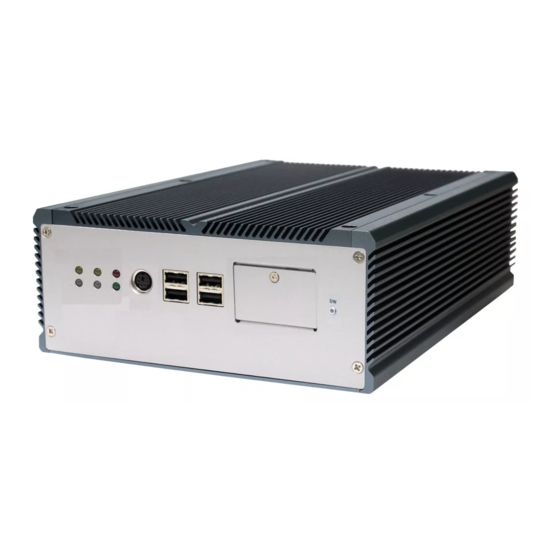
General Information 1.7 Locating Controls and Connectors Both FPC-7500 and FPC-7502 have the same I/O ports and connectors at the front panel. Please take a moment to identify those controls and connectors shown in the following figures. Front Panel LAN2 Active LED CFast/SIM Socket USB Ports LAN1 Active LED... - Page 20 General Information Rear Panel FPC-7500 LAN Ports DIO/LPT/DVI (Selectable) DisplayPort Antenna Port Ant. Optional Line-out Mic-in COM1~COM4 DisplayPort DC IN 10V~28V COM1~4 PCIe Slot DC-IN Ports USB Ports FPC-7502 LAN Ports DIO/LPT/DVI (Selectable) DisplayPort Antenna Port Ant. Optional Line-out Mic-in COM1~COM4 DisplayPort DC IN...
-
Page 21: Connecting Peripherals
General Information 1.8 Connecting Peripherals The user can use the I/O interfaces located at the rear side of the chassis to connect to external peripheral devices, such as a mouse, a keyboard, a monitor, serial devices or parallel printer, etc. Before connection, make sure that the computer and the peripheral devices are turned off. -
Page 22: Serial Ports (Com1 ~4)
General Information 1.8.2 Serial Ports (COM1 ~4) Both FPC-7500 and FPC-7502 are built with an integrated serial ports that combines COM1 ~ COM4 into a D-sub 44-pin female connector. Each port supports RS-232; in addition, COM3, 4 supports RS-232/485 selectable. To connect to any serial device, follow the steps below: 1. -
Page 23: Lan Ports
General Information 1.8.3 LAN Ports Both FPC-7500 & FPC-7502 provide two Intel® WG82574IT 10/100/1000 Base-T Ethernet (RJ-45) interface. For network connection, follow the instructions below: 1. Turn off the BOX PC system and the Ethernet hubs. 2. Plug in one end of cable of a 10/100/1000Base-T hub to the system's RJ-45 jack. -
Page 24: Usb Ports
General Information 1.8.4 USB Ports Both FPC-7500 & FPC 7502 have four USB ports on the front panel and four USB ports on the rear panel to connect to external USB devices. USB ports and devices are hot-pluggable. Therefore, any USB device can be connected at all time without turning off your system. -
Page 25: Keyboard And Mouse
General Information 1.8.5 Keyboard and Mouse Both FPC-7500 & FPC-7502 have one PS/2 keyboard/mouse connector located at the front panel. ACT1 ACT2 LNK1 LNK2 CFast / SIM To connect an AT keyboard, an adapter between the PS/2 interface and the AT Keyboard is needed. -
Page 26: Audio Line-Out/Mic-In
General Information 1.8.7 Audio Line-out/Mic-in Two audio jacks for Line-out and Mic-in located at the rear panel. FPC-7500 Ant. Optional COM1~COM4 DisplayPort DC IN 10V~28V FPC-7502 Ant. Optional COM1~COM4 DisplayPort DC IN 10V~28V - 14 -... -
Page 27: Dc Power Input And Power On/Off Button
General Information 1.8.8 DC Power Input and Power ON/OFF Button For DC power input, the computer is equipped with a 4-pin terminal block receptacle on the rear panel. The “S/W” button located on the front panel is used to power ON/OFF the computer. See the figures below. Front Panel ACT1 ACT2... - Page 28 This page is intentionally left blank. - 16 -...
-
Page 29: Chapter 2 - The Engine Of Fpc-7500/Fpc-7502
The Engine of FPC-7500/FPC-7502 Chapter 2 The Engine of FPC-7500/FPC-7502 - 17 -... -
Page 30: Board Layout
The Engine of FPC-7500/FPC-7502 2.1 Board Layout The engine of FPC-7500 / FPC-7502 is constructed by the combination of one PCBA board. Such a combination makes system customization feasible. Main Board Top View FPC-7500/FPC-7502 Bottom View - 18 -... -
Page 31: Jumpers And Connectors
The Engine of FPC-7500/FPC-7502 2.2 Jumpers and Connectors 2.2.1 Jumpers & Connectors List Jumpers Label Function JBAT1 Clear CMOS Setup JCP1 COM Ports Power Selection JV1 ~ JV4 RI/5V/12V (Pin 9) Selection for Each of the 4 COM Ports Connectors Label Function PWRIN1 Power Input... -
Page 32: Jumper Setting
The Engine of FPC-7500/FPC-7502 2.2.2 Jumper Setting Label Function Jumper Settings 1-2: Keep CMOS (default) JBAT1 Clear CMOS 2-3: Clear CMOS 1-2: +5V (default) JCP1 COM Ports Power Selection 2-3: +12V 1-2: RI (default) RI/5V/12V (Pin 9) Selection JV1~JV4 for Each of the 4 COM Ports 2-3: 5V or 12V (depends on JCP1) SW1, 2, 4 (RS-232/RS-485 Function Select Jumper for COM3, COM4) -
Page 33: Sw2 Setting
The Engine of FPC-7500/FPC-7502 SW2 Setting SW4 Setting COM4 RS-232 RS-485 COM3 RS-232 RS-485 1-16 1-16 2-15 2-15 3-14 3-14 4-13 4-13 5-12 5-12 6-11 6-11 7-10 7-10 2.2.3 Pin Assignments for Connectors PWRIN1 (Power Input) Power Input Terminal Block Receptacle Connector type: 4-pin terminal block Description 1 2 3 4... -
Page 34: Cn1 (Com1 ~ Com4)
The Engine of FPC-7500/FPC-7502 CN1 (COM1 ~ COM4) DB-44 female connector: serial port 1 ~ 4 Desc. Pin Desc. Desc. Pin Desc. COM1 COM2 (RS-232) (RS-232) COM3 COM4 (RS-232) (RS-232) - 22 -... -
Page 35: Cbl-7100-Com (Com Converter Cable) (Optional)
The Engine of FPC-7500/FPC-7502 CBL-7100-COM (COM Converter Cable) (Optional) 1 to 5 COM converter cable: 4 x DB9 male and 1 x DB9 female connectors COM1 (RS-232) labelled CN2 on DB9 Cable Controller DB44 Pin DB9 Pin Desc. DB44 Pin DB9 Pin Desc. - 23 -... - Page 36 The Engine of FPC-7500/FPC-7502 COM2 (RS-232) labelled CN3 on DB9 Cable Controller DB44 Pin DB9 Pin Desc. DB44 Pin DB9 Pin Desc. 232 mode 485 mode COM3 (RS-232) labelled CN4 on DB9 Cable COM3 (RS-485) PIN OUT Controller Signal Desc. Signal Desc.
-
Page 37: Vga1 (Crt Display Connector)
The Engine of FPC-7500/FPC-7502 VGA1 (CRT Display Connector) Three-row/15-pin VGA Connector Pin Description Pin Description Pin Description GREEN VDDAT BLUE HSYNC VSYNC VDCLK DP1 (DisplayPort Connector) Digital Audio/Video Connector Description Description LANE_0P LANE_3N LANE_0N LANE_1P LANE_1N COM3_CTS# LANE_2P AUX_N LANE_2N RTN_PWR LANE_3P - 25 -... -
Page 38: Lan1/2 (Lan Ports)
The Engine of FPC-7500/FPC-7502 LAN1/2 (LAN Ports) RJ-45 Connector Description Pin Description MDI0+ MDI2+ MDI0- MDI2- MDI1+ MDI3+ MDI10- MDI3- USB1/2 (USB Ports) 1 2 3 4 USB 2.0 type A connector 1 2 3 4 Description USB- USB+ AUDIO1 (Audio Jacks) Jack Description Green... -
Page 39: Mc1 (Pcie Mini-Card Socket)
The Engine of FPC-7500/FPC-7502 MC1 (PCIe Mini-card socket) PCI Express MiniCard socket Pin Desc. Pin Desc. Pin Desc. Wake 20 W_Disable# 36 USB_D- +3.3V 21 GND 37 Reserved8 Reserved10 22 PERST# 38 USB_D+ 23 PERn0 39 Reserved7 Reserved9 24 +3.3V 40 GND +1.5V 25 PERp0... -
Page 40: Cpuf1/2 (Fan Connector)
The Engine of FPC-7500/FPC-7502 CPUF1/2 (Fan Connector) Pin Description +12V FAN_CTL KBM1 (Keyboard & Mouse) PS/2 keyboard & Mouse Connector type: 6-pin Mini-DIN connector Description KB_DAT MS_DAT VCC5 KBCLK MSCLK CF1 (CFast Slot) CFast Card Type I/II slot Connector type: 7+17-pin CFast Card connector consisting of a SATA compatible 7-pin signal connector and a 17-pin power and control connector. - Page 41 The Engine of FPC-7500/FPC-7502 Segment Name Type Description Ground for signal SATA SGND Signal GND integrity SATA SATA Differential Signal Pair A SATA SATA Differential Ground for signal SATA SGND Signal GND integrity SATA SATA Differential Signal Pair A SATA SATA Differential Ground for signal SATA...
-
Page 42: Dvi1 (Dvi)
The Engine of FPC-7500/FPC-7502 DVI1 (DVI) Onboard Digital Visual Interface Connector Connector type: 2.00mm pitch 2x17-pin box header Description Description Analog GND Analog GND T.M.D.S. Data2- T.M.D.S. Data2+ DDC Clock DDC Data T.M.D.S. Data1- T.M.D.S. Data1+ Analog GND Analog GND Hot Plug Detect T.M.D.S. -
Page 43: Dio1 (Digital I/O Port)
The Engine of FPC-7500/FPC-7502 DIO1 (Digital I/O Port) Description Description On-board Digital I/O Connector DIO0 DIO1 Connector type: 2.00mm pitch 2x13-pin box header DIO2 DIO3 DIO4 DIO5 DIO6 DIO7 DIO8 DIO9 DIO10 DIO11 DIO12 DIO13 DIO14 DIO15 VCC5 VCC5 LPT1 (Parallel Port) On-board Parallel Port Connector Connector type: 2.00mm pitch Description... -
Page 44: Sata1/2 (Serial Ata Connectors)
The Engine of FPC-7500/FPC-7502 SATA1/2 (Serial ATA Connectors) PWR1/2 (HDD/SSD Power Connectors) On-board Serial ATA Connector Onboard HDD/SSD Power Connector Description Pin Description VCC5 +12V - 32 -... - Page 45 This page is intentionally left blank. - 33 -...
-
Page 46: Chapter 3 - Installation And Maintenance
Installation and Maintenance Chapter 3 Installation and Maintenance - 34 -... -
Page 47: Cpu, Memory And Hsupa Module Installation
Installation and Maintenance 3.1 CPU, Memory and HSUPA Module Installation FPC-7500 / FPC-7502 is designed to be modular, slim and lightweight for easier maintenance. The following sections describe simple hardware installations. 3.1.1 Removing Top Cover 1. Locate the six screws which secure the top cover. 2. -
Page 48: Installing Cpu
Installation and Maintenance 3.1.2 Installing CPU 1. Locate the six screws which secure the Thermal Lump. 2. Use a screwdriver to remove the six screws and keep them safely for later use. 3. The processor socket comes with a screw to secure the CPU. As shown in the picture below, loose the screw first before inserting the CPU. -
Page 49: Installing Memory Module
Installation and Maintenance 3.1.3 Installing Memory Module 1. Locate the 200-pin SO-DIMM slots and press down the clips. 2. Align the SO-DIMM on the slot and let the notch on the SO-DIMM meet the break on the slot. 3. Hold the SO-DIMM with both hands, and gently insert the SO-DIMM into the slot until the clips of the SO-DIMM slot close to lock the memory module in place. -
Page 50: Installing Hsupa 3.75G Module
Installation and Maintenance 3.1.4 Installing HSUPA 3.75G Module 1. Locate Mini Card Slot (refer to Section 2.1 Board Layout for its position), insert the HSUPA module into it at a slanted angle as shown in the picture. Remember to align the notch on module with the break on slot. And then, secure two screws to fasten the module. - Page 51 Installation and Maintenance 2. Press one end of the RF cable into one of the studs named MAIN as shown in the following picture. 3. Push the plastic plug outwards to remove it, so that another end of RF cable, which is a SMA connector jack, can penetrate through antenna hole located on front panel of the chassis.
- Page 52 Installation and Maintenance 4. Mount a round washer into the SMA connector jack from outside before securing another nut into it. 5. At the end, screw antenna into the SMA connector jack and adjust antenna angle for better signal. - 40 -...
-
Page 53: How To Access Cfast/Sim Card
Installation and Maintenance 3.2 How to Access CFast/SIM Card 1. Make sure you have turned off the power before inserting or ejecting the CFast card (if OS is installed on CFast card). 2. Locate the CFast card door on the front panel. 3. - Page 54 Installation and Maintenance 5. After inserting the CFast/SIM card, close the card door and screw it on clockwise. 6. To remove the CFast card or SIM card, follow step 1, 2 and 3 above. And then push card inward to pop-out it from the slot. remove CFast card remove SIM card - 42 -...
-
Page 55: Hard Disk Drive And Pcie Card Installation
Installation and Maintenance 3.3 Hard Disk Drive and PCIe Card Installation 3.3.1 Removing Bottom Cover 1. Place the Box PC upside down. Unscrew the six screws which secure the bottom cover. 2. Use screwdriver to remove the bottom cover screws and keep them safely for later use. - Page 56 Installation and Maintenance 4. Put the HDD into the HDD Holder Bracket and screw it on. 5. Insert HDD adapter to the HDD connector. 6. Hold the HDD Holder Bracket at an angle until the HDD adapter connect to the HDD connector on Main Board. 7.
- Page 57 Installation and Maintenance 10. Thread the cable used to connect main unit and HDD through the hole at one end of HDD Holder Bracket, so that the cable won't be jammed later 11. Plug the cable into HDD's jack, and then lock HDD onto the HDD Holder Bracket by screwing its four side corners.
- Page 58 Installation and Maintenance 13. Plug power line and SATA line in corresponding PWR2 and SATA2 connectors separately. 14. Be sure that SATA cable for second HDD is devised with a lockable function. Therefore, you have to use a tool to press against the little metal clip while you try to unplug SATA cable.
-
Page 59: Installing Pcie Card
Installation and Maintenance 3.3.3 Installing PCIe Card 1. Use a crosshead screwdriver to loose the screw that secure the expansion slot bracket. And then you can install a PCIe card to this expansion slot. 2. If you want to install the PCIe card to the lower slot, please push the rubber cover out of the unit and, through the hole, use the screwdriver to loose the screw securing the lower expansion slot bracket. -
Page 60: Wall Mounting (Optional)
Installation and Maintenance 3.4 Wall Mounting (Optional) 1. Place the main unit upside down on a flat surface and locate the 8 screw holes on the bottom cover. 2. Place the wall-mount brackets horizontally along with bottom cover so that the screw holes are aligned with the ones of the bottom cover. -
Page 61: Grounding The Box Pc
Installation and Maintenance 3.5 Grounding the Box PC Follow the instructions below to ground the computer on the ground. Make sure to follow any grounding requirements at your site. Warning When installing the unit, the ground connection must always be made first and disconnected last. 1. -
Page 62: Wiring The Dc-Input Power Source
Installation and Maintenance 3.6 Wiring the DC-Input Power Source Warning Only trained and qualified personnel should be allowed to install or replace this equipment. Follow the instructions below for connecting the computer to a DC-input power source. 1. Before wiring, make sure the power source is disconnected. 2. - Page 63 This page is intentionally left blank. - 51 -...
-
Page 64: Chapter 4 - Bios
BIOS Chapter 4 BIOS - 52 -... -
Page 65: Bios Main Setup
BIOS 4.1 BIOS Main Setup The AMI BIOS provides a setup utility program for specifying the system configurations and settings which are stored in the BIOS ROM of the system. When you turn on the computer, the AMI BIOS is immediately activated. After you have entered the setup utility, use the left/right arrow keys to highlight a particular configuration screen from the top menu bar or use the down arrow key to access and configure the information below. -
Page 66: Advanced Settings
BIOS System Date Set the system date. Note that the ‘Day’ automatically changes when you set the date. Day : Sun to Sat The date format is: Month : 1 to 12 Date : 1 to 31 Year : 1999 to 2099 System Time Set the system time. - Page 67 BIOS Launch PXE OpROM Enable or disable the boot option for legacy network devices. ACPI Settings Enable/disable the Advanced Configuration and Power Interface (ACPI). CPU Configuration This section is used to configure the CPU. It will also display detected CPU information.
-
Page 68: Acpi Settings
BIOS 4.2.1 ACPI Settings Enable ACPI Auto Configuration This item allows you to enable/disable ACPI (Advanced Configuration and Power Interface) Auto Configuration. Setting: Disabled (Default), Enabled. Enable Hibernation Enable or disable the Hibernation function. This allows the operating system to control power to the computer’s disk, monitor and peripheral devices. Setting: Enabled (Default), Disabled ACPI Sleep State This item allows you to select ACPI Sleep State. -
Page 69: Cpu Configuration
BIOS 4.2.2 CPU Configuration The CPU Configuration setup screen varies depending on the installed processor. Hyper-threading This item is used to enable or disable the processor’s Hyper-threading feature. Enabled for Windows XP and Linux (OS optimized for Hyper-threading Technology) and disabled for other OS (OS not optimized for Hyper-threading Technology). - Page 70 BIOS Limit CPUID Maximum Enable or disable the Limit CPUID Maxium. Hardware Prefetcher Turn on or off the MLC streamer prefetcher. Adjacent Cache Line Prefetch Use this item to enable or disable the adjacent cache line prefetch function. Power Technology Configure the power management features.
-
Page 71: Sata Configuration
BIOS 4.2.3 SATA Configuration It allows you to select the operation mode for SATA controller. SATA Mode Settings: Disable; IDE Mode (Default), AHCI Mode, RAID Mode IDE Mode: Set the Serial ATA drives as Parallel ATA storage devices. AHCI Mode: Allow the Serial ATA devices to use AHCI (Advanced Host Controller Interface). -
Page 72: Intel® Igd Swsci Opregion Configuration
BIOS 4.2.4 Intel® IGD SWSCI OpRegion Configuration Select DVMT/FIXED mode memory size used by Internal Graphics Device. DVMT/FIXED Memory [256 MB] IGD - Boot Type [VBIOS Default] This option allows you to select the display device when you boot up the system. -
Page 73: Usb Configuration
BIOS 4.2.5 USB Configuration Legacy USB Support Enables support for legacy USB. AUTO option disables legacy support if no USB devices are connected. Settings: Enabled (Default); Auto; Disabled EHCI Hand-Off Allows you to enable support for operating systems without an EHCI hand-off feature. -
Page 74: Super Io Configuration
BIOS 4.2.6 Super IO Configuration Parallel Port Configuration This allows you to set parameters of Parallel Port (LPT/LPTE). Power On After Power Fail After Power Failure is a power management option that will set the mode of operation if a power loss occurs. Settings: Power Off: Keep the power off until the power button is pressed. -
Page 75: Pc Health Status
BIOS 4.2.7 PC Health Status PC Health Status The hardware monitor menu shows the operating temperature, fan speeds and system voltages. - 63 -... -
Page 76: Second Super Io Configuration
BIOS 4.2.8 Second Super IO Configuration Serial Port Configuration Use the Serial Port option to enable or disable the serial port. - 64 -... -
Page 77: Platform Thermal Configuration
BIOS 4.2.9 Platform Thermal Configuration Intelligent Power Sharing Enable or disable the power sharing function. - 65 -... -
Page 78: Chipset Settings
BIOS 4.3 Chipset Settings This submenu allows you to configure the specific features of the chipset installed on your system. The chipset manage bus speeds and access to system memory resources, such as DRAM. It also coordinates communications with the PCI bus. Notice Beware of that setting inappropriate values in items of this menu may cause system to malfunction. -
Page 79: North Bridge
BIOS 4.3.1 North Bridge Memory Information The item displays the detected system memory information. Low MMIO Align This option will determine Low MMIO resources align. Initiate Graphic Adapter This item allows you to select which graphics controller to use as the primary boot device. -
Page 80: South Bridge Configuration
BIOS 4.3.2 South Bridge Configuration SMBus Controller Enable or disable the SMBus controller. SLP_S4 Assertion Stretch Enable Enable or disable the SLP_S4 Stretch function. Azalia HD Audio Use the Azalia HD Audio option to enable or disable the High Definition Audio controller. -
Page 81: Boot Settings
BIOS 4.4 Boot Settings The Boot menu items allow you to change the system boot options. Quiet Boot This allows you to select the screen display when the system boots. Fast Boot During the POST (Power On Self Test), the BIOS checks the hardware devices and counts the system memory. - Page 82 BIOS Bootup NumLock State This setting determines whether the Num Lock key should be activated at boot up. Gate A20 Active This item is to set the Gate A20 status. Option ROM Messages This item is to set display mode for Option ROM. Interrupt 19 Capture When enabled, it allows the optional ROM to trap interrupt 19.
-
Page 83: Security
BIOS 4.5 Security Administrator Password Use the Administrator Password to set or change a administrator password. ENTER PASSWORD Type the password, up to eight characters in length, and press <Enter>. The password typed now will clear any previously entered password from CMOS memory. - Page 84 BIOS time you try to enter Setup. This prevents an unauthorized person from changing any part of your system configuration. Additionally, when a password is enabled, you can also require the BIOS to request a password every time your system is rebooted. This would prevent unauthorized use of your computer.
-
Page 85: Save & Exit
BIOS 4.6 Save & Exit Save Changes and Reset Pressing <Enter> on this item and it asks for confirmation: Save configuration changes and exit setup? Pressing <OK> stores the selection made in the menus in CMOS - a special section of memory that stays on after you turn your system off. The next time you boot your computer, the BIOS configures your system according to the Setup selections stored in CMOS. - Page 86 BIOS Discard Changes and Reset Exit system setup without saving any changes. <ESC> key can be used for this operation. Save Options Restore Defaults Restore system to factory default. Pressing <Enter> on this item and it asks for confirmation prior to executing this command.
- Page 87 This page is intentionally left blank. - 75 -...
-
Page 88: Appendix
Appendix Appendix - 76 -... -
Page 89: Appendix A: I/O Port Address Map
Appendix Appendix A: I/O Port Address Map Each peripheral device in the system is assigned a set of I/O port addresses which also becomes the identity of the device. The following table lists the I/O port addresses used. Address Device Description 00000000 - 00000CF7 PCI bus 00000000 - 00000CF7... - Page 90 Appendix 000000A2 - 000000BF Motherboard resources 000000C0 - 000000DF Direct memory access controller 000000E0 - 000000EF Motherboard resources 000000F0 - 000000FF Numeric data processor 00000274 - 00000277 ISAPNP Read Data Port 00000279 - 00000279 ISAPNP Read Data Port 00000290 - 0000029F Motherboard resources 000002E8 - 000002EF Communications Port (COM4)
-
Page 91: Appendix B: Interrupt Request Lines (Irq)
Appendix 0000F070 - 0000F077 Intel(R) 5 Series 6 Port SATA AHCI Controller 0000F080 - 0000F087 Intel(R) HD Graphics Appendix B: Interrupt Request Lines (IRQ) Peripheral devices use interrupt request lines to notify CPU for the service required. The following table shows the IRQ used by the devices on board. Level Function IRQ 0... -
Page 92: Appendix C: Memory Mapping
Appendix IRQ 19 Intel(R) 5 Series 6 Port SATA AHCI Controller Standard Dual Channel PCI IDE Controller IRQ 22 Microsoft UAA Bus Driver for High Definition Audio IRQ 23 Intel(R) 5 Series/3400 Series Chipset Family USB Enhanced Host Controller - 3B34 Appendix C: Memory Mapping Address Device Description... - Page 93 Appendix FED90000 - FED93FFF System board FED20000 - FED3FFFF System board FEE00000 - FEE0FFFF System board FED1C000 - FED1FFFF System board FEC00000 - FECFFFFF System board FED08000 - FED08FFF System board FF000000 - FFFFFFFF System board A0000 - BFFFF PCI bus A0000 - BFFFF Intel(R) HD Graphics - 81 -...
-
Page 94: Appendix D: Digital I/O Setting
Appendix Appendix D: Digital I/O Setting Digital I/O can read from or write to a line or an entire digital port, which is a col- lection of lines. This mechanism can be used to meet user’s various applica- tions such as industrial automation, customized circuit, and laboratory testing. The source code below written in C is the applicable sample for programming. - Page 95 Appendix Index 41, GPIO3x Output Data value SMB_Byte_WRITE(SMB_PORT_AD,SMB_DEVICE_ADD,0x41,0x00); delay(10); //---------------------------------------------------------------------------- unsigned char SMB_Byte_READ (int SMPORT, int DeviceID, int REG_IN- DEX) unsigned char SMB_R; outportb(SMPORT+02, 0x00); /* clear */ outportb(SMPORT+00, 0xff); /* clear */ delay(10); outportb(SMPORT+04, DeviceID+1); /* clear */ outportb(SMPORT+03, REG_INDEX); /* clear */ outportb(SMPORT+02, 0x48);...
-
Page 96: Appendix E: Watchdog Timer (Wdt) Setting
Appendix Appendix E: Watchdog Timer (WDT) Setting WDT is widely applied to industry computers to monitor activities of CPU. The programmed application triggers WDT with adequate timer setting depending on its requirement. Before WDT counts down to zero, the functional system will reset the counter.
Need help?
Do you have a question about the FPC-7500 Series and is the answer not in the manual?
Questions and answers