
Subscribe to Our Youtube Channel
Related Manuals for Arbor Technology M1858


Summary of Contents for Arbor Technology M1858
- Page 1 M1858 18.5" Fanless Intel Atom N2800 1.86GHz Medical PC User's Manual Version 2.0 P/N: 4012185800200P 2013.12...
- Page 2 This page is intentionally left blank. - 2 -...
- Page 3 Revision History Version Release Time Description July 2012 Initial release The computer newly features a wired remote controller which gives rise to the following changes in this manual: 1.3.1. Optional Accessories updated Appendix D. Remote Controller (Optional) newly added. The other adjustments: 2.4.
- Page 4 This page is intentionally left blank. - ii -...
-
Page 5: Table Of Contents
Contents Contents Revision History ....................i Contents .......................iii Preface......................v Copyright Notice....................v Declaration of Conformity..................v CE .........................v IEC 60601-1/EN60601-1/EN60601-1-2 ............vi SVHC / REACH ..................vii About This User’s Manual .................. vii Technical Support....................vii Important Safety Instructions ................viii Classification .......................ix Disposing of the Computer..................ix General Cleaning Tips..................x Symbols Description ...................xi Warranty ...................... -
Page 6: Contents
Contents Chapter 4 - BIOS ..................43 4.1. BIOS Main Setup ..................44 4.2. Advanced Settings ..................46 4.2.1. CPU Configuration ................47 4.2.2. IDE Configuration................47 4.2.3. Super IO Configuration ..............48 4.3. Chipset Settings ..................49 4.4. Boot Settings ....................50 4.5. Security .......................51 4.6. Exit Options ....................53 Appendix .....................55 A. -
Page 7: Preface
Preface Preface Copyright Notice All Rights Reserved. The information in this document is subject to change without prior notice in order to improve the reliability, design and function. It does not represent a commitment on the part of the manufacturer. Under no circumstances will the manufacturer be liable for any direct, indirect, special, incidental, or consequential damages arising from the use or inability to use the product or documentation, even if advised of the possibility of such... -
Page 8: Iec 60601-1/En60601-1/En60601-1-2
RoHS ARBOR Technology Corp. certifies that all components in its products are in compliance and conform to the European Union’s Restriction of Use of Hazardous Substances in Electrical and Electronic Equipment (RoHS) Directive 2002/95/EC. -
Page 9: Svhc / Reach
Preface exceed 0.01% by weight, per homogenous material. Homogenous material is defined as a substance or mixture of substances with uniform composition (such as solders, resins, plating, etc.). Lead-free solder is used for all terminations (Sn(96-96.5%), Ag(3.0-3.5%) and Cu(0.5%)). SVHC / REACH To minimize the environmental impact and take more responsibility to the earth we live, Arbor hereby confirms all products comply with the restriction of SVHC (Substances of Very High Concern) in (EC) 1907/2006 (REACH --Registration,... -
Page 10: Important Safety Instructions
Preface Contact Information Add: 10F., No.700, Zhongzheng Rd., Zhonghe Dist., New Taipei City 235, Taiwan TEL: 886-2-8226-9396 Important Safety Instructions Read these safety instructions carefully: 1. Read all cautions and warnings on the equipment. 2. Place this equipment on a reliable surface when installing. Dropping it or letting it fall may cause damage 3. -
Page 11: Classification
Preface b. Liquid has penetrated into the equipment. c. The equipment has been exposed to moisture. d. The equipment does not work well, or you cannot get it to work according to the user’s manual. e. The equipment has been dropped or damaged. The equipment has obvious signs of breakage. -
Page 12: General Cleaning Tips
Preface current European Union Member States. • Outside the European Union If you wish to dispose of used electrical and electronic products outside the European Union, please contact your local authority so as to comply with the correct disposal method. General Cleaning Tips You may need the following precautions before you begin to clean the device. -
Page 13: Symbols Description
Preface • Cotton swabs: Cotton swaps moistened with rubbing alcohol or water are excellent tools for wiping hard to reach areas in your keyboard, mouse, and other locations. • Foam swabs: Whenever possible, it is better to use lint-free swabs such as foam swabs. -
Page 14: Warranty
Preface Change of electric current: Internal: positive current External: negative current Launches the utility that controls some features of the computer. (See 3.1. Use Function Keys for the MENU button.) Enables/disables the phone. (See 2.2. Tour the Computer for the Phone on/off button.) Volume up/down (See 2.2. -
Page 15: Chapter 1 - General Information
Chapter 1 General Information Chapter 1 - General Information - 1 -... -
Page 16: Introduction
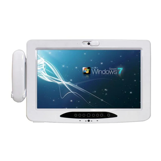
Atom™ N2800 processor and fanless design, the computer ® is suitable for the uses in hospitals and clinics. M1858 is also an entertainment and information terminal for patients during their stay in hospital. The 18” touch screen, definable function keys and abundant expansions make it more convenient for clinicians and patients to operate. -
Page 17: Ordering Information
General Information 1 x power cord (Left, French standard cordset) 1 x power cord (Right, American standard cordset) 1 x 60W medical-grade AC/DC adapter kit 1.3. Ordering Information M1858 18.5" fanless Intel Atom™ N2800 1.86GHz medical PC ® ARM-1552M Wall-mount hospital arm (VESA-75/100) L=1907 mm... -
Page 18: Optional Configuration (Configure-To-Order Service)
General Information 1.3.2. Optional Configuration (Configure-to-Order Service) RFID-1858 RFID module kit BarC-1858 Barcode scanner module kit BT-1858 Bluetooth module kit KBR-1858 RF keyboard receiver kit - 4 -... -
Page 19: Specifications
General Information 1.4. Specifications System Intel® Atom™ Dual Core N2800 1.86GHz processor Chipset Intel® NM10 Memory 2GB DDR3 SO-DIMM memory module installed Storage 2.5” 320GB SATAII HDD or 2.5” 32GB SATA SSD Windows 7-32 bit OS support Linux Ubuntu and Fedora compliant Peripherals &... - Page 20 General Information Contrast Ratio 1000 : 1 (typ.) Backlight Type Backlight Life Time 30,000 hours Touch Screen Type Analog Resistive Touch, 5 wire Light Transparency 80% (typ.) Controller Interface USB interface Mechanical & Environmental Operating Temp. 0 ~ 40°C (32 ~ 104°F) Operating Humidity 5 ~ 95% (non-condensing) Dimensions (W x 558 x 337 x 66mm (21.97”...
-
Page 21: Chapter 2 - Getting Started
Chapter 2 Getting Started Chapter 2 - Getting Started - 7 -... -
Page 22: Dimensions
Getting Started 2.1. Dimensions Unit: mm - 8 -... -
Page 23: Tour The Computer
Getting Started 2.2. Tour the Computer Understanding the computer help you jump seamlessly from component to component when using the computer. This section will quickly familiarize you with the computer. Front View built-in 5.0 Camera VoIP Phone Privacy Cover (optional) RFID (optional) Phone on/off Power on/off... - Page 24 Getting Started Note: 1. To turn on the medical PC, press-and-hold the “Power” button until the computer powers on. 2. The audio system of this medical PC is switched between the AC97’ Phone and the speaker of the medical PC. For instance, when you pick up the phone, the audio is switched to the phone so that phone conversation can be carried out.
- Page 25 Getting Started Rear Side The rear side are recessed with one power jack, one coaxial port and one LAN port. DC-IN Power Jack Nurse Call Function Reserved LAN Port Coaxial Port Dual 3Watt Speakers Warning: The aluminum plate on the rear panel is highly heated when the medical PC is operating.
- Page 26 Getting Started Bottom Side Barcode Scanner 1 x speaker-out A/V Input (optional) 1 x Mic-in Phone Jack Remote Controller port USB Ports DC-in Power Jack COM Port (RS-232) Right Side Left Side 2 x Smart Card Reader Slot - 12 -...
-
Page 27: Periodic Cleaning & Disinfection
Getting Started 2.3. Periodic Cleaning & Disinfection This panel PC is generally employed in medical environment, for example, hospitals, as bedside infotainment (information plus entertainment). It is strongly recommended that users follow the cleaning and disinfection instructions described below to ensure proper maintenance activities. 1. - Page 28 Getting Started Caution: • Do not spill liquids on or around the medical PC. • Do not use other solutions than the ones mentioned above. • Do not touch, press or rub the display panel with abrasive cleaning compounds, instruments, brushes, or rough-surface materials. •...
-
Page 29: Install Drivers And Utilities
Getting Started 2.4. Install Drivers and Utilities The computer supports Windows 7. Find the necessary device drivers on the CD that comes with your purchase. 2.4.1. Installation Sequence Always follow the sequence below to install the drivers to prevent errors: Chipset →... - Page 30 Getting Started Then follow the guideline below to install device drivers and utilities: 1. Connect the computer to external power by the power cable and adapter included in the accessory box. power outlet power cable power adapter the computer 2. Have the USB CD-ROM drive. Connect the CD-ROM drive to the computer (, and sometimes the connection to power supply is also needed depending on the feature of your CD-ROM drive).
- Page 31 Getting Started In a few seconds, a dialog opens asking whether to auto-run the driver CD or open the CD contents in Windows Explorer. 5. Click/tap Run AUTORUN.EXE to auto-run the driver CD, which allows easier installation of drivers. The installer then opens. - 17 -...
- Page 32 Getting Started 6. Click/tap Win7 Driver Install. Click/tap the Browse CD button to view the CD contents in Windows Explorer. A list of device drivers then opens onscreen. 7. Click on the title of a driver to install it. Always follow the sequence described in 2.4.1.
-
Page 33: Install Chipset Driver
Getting Started 2.4.3. Install Chipset Driver To install the chipset driver: 1. Launch the driver installer as described in 2.4.2. Start to Install on page and open the driver list. The driver list then opens onscreen. 2. Click/tap the Chipset icon 3. -
Page 34: Install Graphics Driver
Getting Started 2.4.4. Install Graphics Driver To install the graphics driver: 1. Launch the driver installer as described in 2.4.2. Start to Install on page and open the driver list. The driver list then opens onscreen. 2. Click/tap the VGA icon 3. -
Page 35: Install Audio Driver
Getting Started 2.4.5. Install Audio Driver To install the audio driver: 1. Launch the driver installer as described in 2.4.2. Start to Install on page and open the driver list. The driver list then opens onscreen. 2. Click/tap the Audio icon 3. -
Page 36: Install Lan Driver
Getting Started 2.4.6. Install LAN Driver To install the LAN driver: 1. Launch the driver installer as described in 2.4.2. Start to Install on page and open the driver list. The driver list then opens onscreen. 2. Click/tap the LAN icon 3. -
Page 37: Install Touch Screen Driver
Getting Started 2.4.7. Install Touch Screen Driver To install the touch screen driver: 1. Launch the driver installer as described in 2.4.2. Start to Install on page and open the driver list. The driver list then opens onscreen. 2. Click/tap the Touch Screen icon 3. -
Page 38: Install Wifi Driver
Getting Started 2.4.8. Install WiFi Driver To install the WiFi driver: 1. Launch the driver installer as described in 2.4.2. Start to Install on page and open the driver list. The driver list then opens onscreen. 2. Click/tap the WiFi icon 3. -
Page 39: Install Function-Keys Driver
Getting Started 2.4.9. Install Function-Keys Driver To install the driver for the function keys: 1. Launch the driver installer as described in 2.4.2. Start to Install on page and open the driver list. The driver list then opens onscreen. 2. Click/tap the Function Keys icon 3. -
Page 40: Install Camera Driver
Getting Started 2.4.10. Install Camera Driver To install the camera driver: 1. Launch the driver installer as described in 2.4.2. Start to Install on page and open the driver list. The driver list then opens onscreen. 2. Click/tap the CCD Codec icon 3. -
Page 41: Install Bluetooth Driver And Utility
Getting Started 2.4.11. Install Bluetooth Driver and Utility To install the driver and utility for Bluetooth (configure-to-order): 1. Launch the driver installer as described in 2.4.2. Start to Install on page and open the driver list. The driver list then opens onscreen. 2. -
Page 42: Install Rfid Reader Driver
Getting Started 2.4.12. Install RFID Reader Driver To install the driver for the RFID reader (configure-to-order): 1. Launch the driver installer as described in 2.4.2. Start to Install on page and open the driver list. The driver list then opens onscreen. 2. -
Page 43: Chapter 3 - Use The Computer
Chapter 3 Use the Computer Chapter 3 - Use the Computer - 29 -... -
Page 44: Use Function Keys
Use the Computer After all drivers are installed as described in 2.4. Install Drivers and Utilities page 15, you can start to use the computer. The chapter will walk through the essential features of the computer. 3.1. Use Function Keys 1. - Page 45 Use the Computer 2. You can also activate menu window from All Programs. Please click ArborTabletui. 3. An icon appears in task tray immediately. Right-click the icon and select Show to call menu window. - 31 -...
- Page 46 Use the Computer 4. Or you can select Set Function Keys to change default setting. Except Brightness up/down, Screen on/off and Power on/off buttons on front panel, you can set other buttons. 5. Click inverted triangle to extend drop-down menu and choose new function. - 32 -...
- Page 47 Use the Computer 6. Or you can choose Program to set Function Keys as any program’s hot key. - 33 -...
-
Page 48: Calibrate Touch Screen
Use the Computer 3.2. Calibrate Touch Screen 1. After installing the touch screen driver, a set of shortcuts will be generated in All Programs. Please click TouchMon. 2. An icon appears in task tray immediately. Right-click the icon to call sub- menu. - Page 49 Use the Computer 3. The whole screen will turn to white and a red point rounded by a red circle with arrows shows up. Meanwhile, countdown in the grey circle also starts from 15th second. Please touch red point and hold until the grey circle shows 'OK'.
- Page 50 Use the Computer 4. Or you may execute calibration from shortcut on desktop (or Configure Utility item in All Programs). Click eGalaxTouch icon. 5. Select Tools tab and click 4 Points Calibration. Note: For more detailed about other tabs, see Appendix H.
-
Page 51: Use Wifi
Use the Computer 3.3. Use WiFi 1. Single-click WiFi icon in task tray to activate WiFi. 2. The list shows every WiFi Connection detected near your medical PC. Choose a specific one and enter connection password to access WiFi connection. - 37 -... -
Page 52: Use Ccd Camera
Use the Computer 3.4. Use CCD Camera 1. Once everything is stalled correctly, you may find a program name LEAD Converter, which can test CCD Camera although you may install your own application. 2. Click upper-left corner to switch to Capture mode. - 38 -... - Page 53 Use the Computer 3. Set destination folder. - 39 -...
- Page 54 Use the Computer 4. Click Preview and the window below will jump out showing video the CCD camera records. - 40 -...
-
Page 55: Use Smart Card Readers
Use the Computer 3.5. Use Smart Card Readers 1. You may install your own Smart Card Reader application; however, our driver CD incorporates a program to test this device. Please execute DEMO4.exe from the following path: disk drive\Windows 7\Smart Card Reader Tool 2. - Page 56 Use the Computer 3. Click Select reader. A sub-window will jump out to ask which reader you want to test. Pleaser select Reader 0. Reader 1 represents the lower reader. Click OK to close the sub-window. Then, click Connect. If Reader 0 successfully detects smart card, its information will be shown in box below.
-
Page 57: Chapter 4 - Bios
Chapter 4 BIOS Chapter 4 - BIOS - 43 -... -
Page 58: Bios Main Setup
BIOS 4.1. BIOS Main Setup The AMI BIOS provides a Setup utility program for specifying the system configurations and settings. The BIOS RAM of the system stores the Setup utility and configurations. When you turn on the computer, the AMI BIOS is immediately activated. - Page 59 BIOS Key Commands BIOS Setup Utility is mainly a key-based navigation interface. Please refer to the following key command instructions for navigation process. “←”“→” Move to highlight a particular configuration screen from the top menu bar / Move to highlight items on the screen “↓”...
-
Page 60: Advanced Settings
BIOS 4.2. Advanced Settings The “Advanced” setting page provides you the options to configure the details of your hardware, such as barcode scanner, phone button, CPU, IDE and Super IO (input/output). Barcode Scanner Configuration Enable/Disable Barcode scanner. Default is disabled. Phone Button Configuration Enable/disable the Phone on/off button. -
Page 61: Cpu Configuration
BIOS 4.2.1. CPU Configuration The tab displays CPU Configuration Parameters. 4.2.2. IDE Configuration The tab displays IDE Devices Configuration. - 47 -... -
Page 62: Super Io Configuration
BIOS 4.2.3. Super IO Configuration Configure Super IO Chip Parameters. Power On After Power Fail Specify what state to go to when power is re-applied after a power failure. The choice: Power Off, Power On - 48 -... -
Page 63: Chipset Settings
BIOS Serial Port0/1 Configuration Serial Port Enable/Disable Serial Port. Change Settings Select an optimal setting for Super IO device. 4.3. Chipset Settings - 49 -... -
Page 64: Boot Settings
BIOS Host Bridge Display Host Bridge Parameters. 4.4. Boot Settings Set your device booting preferences. - 50 -... -
Page 65: Security
BIOS Bootup NumLock State This setting determines whether the Num Lock key should be activated at boot up. Quiet Boot This setting determines if the BIOS should hide the normal POST messages with the motherboard or system manufacture’s full-screen logo. When it is enabled, the BIOS will display the full-screen logo during the boot-up sequence, hiding normal POST messages. - Page 66 BIOS Administrator Password Set Change Administrator Password to enter and change the options of the setup menus. When you select this function, the following message will appear at the center of the screen to assist you in creating a password. Enter New Password: Type the password, up to six characters in length, and press <Enter>.
-
Page 67: Exit Options
BIOS 4.6. Exit Options Save Changes and Exit Pressing <Enter> on this item and it asks for confirmation: Save configuration changes and exit setup? Pressing <OK> stores the selection made in the menus in CMOS - a special section of memory that stays on after you turn your system off. The next time you boot your computer, the BIOS configures your system according to the Setup selections stored in CMOS. - Page 68 This page is intentionally left blank. - 54 -...
-
Page 69: Appendix
Appendix Appendix - 55 -... -
Page 70: Medical Arm (Optional)
Appendix A. Medical Arm (Optional) This medical PC can be mounted on a wall-mount, desktop-stand, or hospital arm for convenient operation. To mount it on a hospital arm, you need cross- headed screwdriver, and M6 size screws. Due to mechanical design, we don’t suggest you screw arm via VESA 75 holes (inner square), or you may risk the danger of damaging the PC in serious case. -
Page 71: Voip Phone (Optional)
Appendix B. VoIP Phone (Optional) The VoIP phone (Voice Communication by IP) is software activated. Users can install software to enable phone communication. (one widely known example is Skype). Note: The audio system of this medical PC switches between AC97’ Phone and speakers of the medical PC itself. -
Page 72: Rf Keyboard (Optional)
Appendix C. RF Keyboard (Optional) This section will walk you through the features of the RF keyboard, RFKB-1858. *Note: When starting up the computer for the first time, press-and-hold the “space key” to pair the keyboard and the computer. C.1. Specifications 135 x 45 x 10mm (21.97”... -
Page 73: Function Keys
Appendix C.3. Function Keys Function Key Definition Pairing key Function key I Function key II Capitalizes all letters entered Switches between opened windows = Alt +Tab Switches between the navigation keys and mouse pointer Maximizes/restores the current window - 59 -... -
Page 74: Key Combination
Appendix C.4. Key Combination Combination Keys Definition Generate the number “8”, and so Generates the symbol “#”, and so Opens the desktop Mutes the audio Closes the window Increases the volume Decreases the volume Mouse right-click Power off Full-screen switch (Alt + Enter) - 60 -... -
Page 75: Remote Controller (Optional)
Appendix D. Remote Controller (Optional) The RC-M185X, a wired remote controller that doubles as a VoIP phone, is designed for the computer and provided on option. This section will detail the features of this optional accessory. D.1. Specifications 180 x 54 x 29mm (7.09” x 2.13” x 1.14”) Dimensions (W x D x H) 108g Weight... -
Page 76: Keyboard
Appendix D.3. Keyboard The keyboard is provided on the front side of the device. It features a few function keys to launch actions from the computer, a set of navigation keys to facilitate users’ onscreen navigation and also a set of numeric keys to enable TV channels selection or even numeric characters input. -
Page 77: Use Fn Key
Appendix Key / Keypad Description key, a modifier key to shift the function of some other key. Nurse-call button D.4. Use Fn key Hit the Fn key to change what the next key pressed delivers. The Fn key doesn’t produce any function if it is pressed alone. Once the Fn key is hit, its LED lights white. -
Page 78: Program Your Own Remote Controller Applications
Appendix D.5. Program Your Own Remote Controller Applications The computer provides users with a software development kit to support them programming their own remote controller applications. See the following for the key mapping table and sample codes. D.5.1. Key Mapping Table Remote Key Key Code Scan Code... - Page 79 Appendix Vol + Vol + Vol - Vol - Nurse Call D.5.2. Linux Sample Code Note: NumLock isn’t enabled upon Linux boot-up. Must make sure NumLock is active for keypad numbers. Use “apt-get install numlockx” or “yum install numlockx” to enable NumLock during application starting. See the sample code hereunder.
- Page 80 Appendix if ( ( m_OutBuf&0x00000002) == 0 ) break; if ( i < 3999 ) outb_p(m_ECDATA, 0x68); for ( i=0; i<=4000; i++ ) m_OutBuf=inb_p(0x6C); if ( ( m_OutBuf&0x00000002) == 0 ) return 0x00000000; if ( i > 3999 ) m_OutBuf=inb_p(0x68); return 0xFFFFFFFF;...
- Page 81 Appendix unsigned long ECU_Read_686C_RAM_BYTE( unsigned long ECUMemAddr ) unsigned long uDATA1,uDATA2,ECRamAddrH,ECRamAddrL; ECRamAddrL=ECUMemAddr%256; ECRamAddrH=ECUMemAddr/256; uDATA1=Process_686C_Command_Write(0x000000A3, ECRamAddrH ); if ( uDATA1==0xFFFFFFFF ) { return 0xFFFFFFFF; } uDATA1=Process_686C_Command_Write(0x000000A2, ECRamAddrL ); if ( uDATA1==0xFFFFFFFF ) { return 0xFFFFFFFF; } uDATA1=Process_686C_Command_Read( 0x000000A4 ); if ( uDATA1 > 0x000000FF ) { return 0xFFFFFFFF; } uDATA2=Process_686C_Command_Read( 0x000000A4 );...
- Page 82 Appendix struct input_event ie; int LCDStatus = 1; system(“/usr/bin/numlockx on”); //enable NumLock res=iopl(3); setuid(500); keyfd fopen(“/dev/input/event16”, “r”); //application must choose correct event for remote control if(keyfd != NULL) while(1) fread((void *)&ie, sizeof(ie), 1, keyfd); if (ferror(keyfd)) perror(“fread”); exit(1); if(ie.code == 1 && ie.value == 1) //ESC //exit application printf(“Exit\n”);...
- Page 83 Appendix if(temp == 0xFFFFFFFF) temp = ECU_Read_686C_RAM_ BYTE(0x1604); if(temp != 0xFFFFFFFF) //backlight off temp &= 0xBF; E C U _ W r i t e _ 6 8 6 C _ R A M _ BYTE(0x1604,temp); temp ECU_Read_686C_RAM_ BYTE(0x1605); if(temp == 0xFFFFFFFF) temp = ECU_Read_686C_RAM_ BYTE(0x1605);...
- Page 84 Appendix BYTE(0x1605,temp); if(ie.code == 190 && ie.value == 1) //F20 printf(“Video Switch\n”); if(ie.code == 189 && ie.value == 1) //F19 printf(“CH +\n”); if(ie.code == 188 && ie.value == 1) //F18 printf(“CH -\n”); if(ie.code == 187 && ie.value == 1) //F17 printf(“Nurse Call\n”);...
-
Page 85: Use Barcode Scanner (Configure-To-Order)
Appendix E. Use Barcode Scanner (Configure-to-Order) 1. To use the barcode scanner, access the system BIOS and enable the device first since the device is disabled by default. (See also Chapter 4 - BIOS more details about the BIOS Setup utility.) 2. - Page 86 Appendix 3. Launch a text editor in the system, for example the Windows’ native Notepad. Click the barcode scanner icon to read, decode and output the barcode to a *.txt file. Note: The scanning light will stay on for 12 seconds. If no barcode is within the reach of the scanning light and no barcode is read within the 12 seconds, the scanning light will auto-stop when 12 seconds elapse.
- Page 87 Appendix Linear Matrix BC412 (requires end-user license from Aztec IBM) China Post Chinese Sensible Code (Han Xin Code) Codabar (NW7) Data Matrix Code 11 Grid Matrix Code Code 128 MaxiCode Code 32 QR Code Code 39 Micro QR Code Postal Code 93 and 93i Code 2 of 5 Intelligent Mail Barcode...
-
Page 88: Use Rfid Reader (Configure-To-Order)
Appendix F. Use RFID Reader (Configure-to-Order) Once the driver for the RFID reader is installed, an RFID NFC Demon shortcut will show up on the desktop. The RFID NFC Demon is a test program for you to see whether the RFID reader works correctly. - Page 89 Appendix 3. From the menu bar, click Mode | Reader. A Reader Mode window opens. 4. Click the Inventory tab. The Inventory tabbed page opens. - 75 -...
- Page 90 Appendix 5. Click the Start button. The table on the Inventory tabbed page starts to show the column titles including UID No, Read Count and Protocol. And the RFID reader is ready to read any supported RFID tag in range. 6.
-
Page 91: Use Bluetooth (Configure-To-Order)
Appendix G. Use Bluetooth (Configure-to-Order) 1. As long as the driver is installed as described in 2.4.11. Install Bluetooth Driver and Utility on page 27, the Bluetooth is ready-to-use. Click the Bluetooth Places icon on the desktop to enable the Bluetooth module and launch the utility. -
Page 92: Egalax Utilities
Appendix H. eGalax Utilities H.1. TouchMon Utility eGalax software package contains an utility to monitor some events related to touchscreen application. After installing the eGalax software package, you will see the icon appearing in the system tray on the right side of the taskbar. Whenever the mouse cursor moves on the tray icon, a tool tip shows as below. - Page 93 Appendix Apply To Touchscreen When users select this function, the sub-menu shows all of the eGalax devices installed in the system. Users can choose the devices to which the next function configuration to be applied. TouchMon allows the configuration to be applied to all of the eGalax devices or some specified devices. Apply to Touchscreen Mouse Mode The Mouse mode has a sub-menu to show all of the mouse emulation modes...
- Page 94 Appendix Beep This function allows users to change the beep mode between "Beep On Touch," "Beep On Release," "Beep From System Beep," and "Beep From Sound Card." The change is applied to the specified devices immediately. Auto Right Click Users can enable/disable the auto right click function. The change is applied to the specified devices immediately.
-
Page 95: Touch Screen Configuration Utility
Appendix H.2. Touch Screen Configuration Utility Besides the TouchMon pop-up menu, users can also double click the icon on the desktop or the shortcut on the All Programs menu to run the touch screen configuration utility. By default the General tab shows up in the eGalax window when the utility is launched. - Page 96 Appendix Remove This function button is used for serial RS-232 controllers only. The button will be greyed and disabled automatically when the selected controller in the controller list window is not RS-232 type. Press to remove and uninstall the selected serial RS-232 controller from the system. Then, this serial RS-232 icon in the controller list window disappears automatically.
- Page 97 Appendix H.2.2. Setting Tab The Setting tab allows users to adjust the settings including beep timing, linearization style, mouse click, etc. Beep • Beep On Touch Tick this check box to generate a beep sound when the touchscreen is pressed. •...
- Page 98 Appendix Linearization Style Select the radio button of 9 points or 25 points calibration for linearization. Double Click Time The Double Click Time group is used to set system double click time. Change this value will affect the double click behavior for all of the mice devices in the system.
- Page 99 Appendix H.2.3. Option Tab By pressing the Option button, another window shows up above the eGalax utility for some advanced functions configuration. The advanced functions include: • Enable Constant Touch Enable Constant Touch to force driver to stop reporting touch point when the movement is within the range which users can adjust.
- Page 100 Appendix The advanced functions include: • Enable Constant Touch Enable Constant Touch to force driver to stop reporting touch point when the movement is within the range which users can adjust. Therefore, users can see a stabilized cursor instead of a chattering cursor when users touch the same point with unwanted noise.
- Page 101 Appendix H.2.4. Tool Tab Besides viewing the linearization curve of the touchscreen, users can also perform the multi-points calibration and the draw test by clicking the buttons on the tab. • Linearization Curve Linearization curve of the touchscreen is displayed here for reference and troubleshooting purpose.
- Page 102 Appendix • Linearization The Linearization (this function may be 25 or 9 points calibration depending on the linearization style, see the Setting tab) function is used to compensate the touchscreen linearity. After linearization is completed, the linearity of the touchscreen will be shown in the Linearity Curve window. Pressing this button, the whole screen appears in white and a red point round- ed by a red circle with arrows shows up.
- Page 103 Appendix Drawing Test Grid - 89 -...
- Page 104 Appendix H.2.5. Display Tab eGalax driver utility supports multiple monitors display system. To work with multiple monitors system, users need to configure properly to map the touch- screen working area to the correct system display area. Note: TouchMon is another utility for eGalax touchscreen system. This tray icon utility can monitor the system monitor display configuration change and correct the touchscreen monitor mapping relationship automatically as soon as the system monitor display configuration is changed.
- Page 105 Appendix • Map to main display if system has only one display monitor Tick this check box to enable the function mapping the touch panel to the main display when the system has only one display monitor. • Operation Mode eGalax driver support split display mode for those applications which do not map the touchscreen to the full screen of the monitor.
- Page 106 Appendix Quarter 3 The touchscreen will be mapped to the 3rd quarter area of the specified monitor display. Quarter 4 The touchscreen will be mapped to the 4th quarter area of the specified monitor display. Customized With the Customized radio button selected, the four column fields labelled Left, Right, Top, and Bottom show the current resolution of display and users can set up the activate area by inputting the value in each column field or clicking the Drag Working Area button to manually drag the working area.
- Page 107 Appendix DragWorkingArea With the DragWorkingArea button clicked, the image will switch back to the desktop. Users can customize the working area by dragging a rectangle on the desktop. Then click Confirm to set the working area, or click Quit to cancel. Dragging a Rectangle to Set the Working Area - 93 -...
- Page 108 Appendix » Active Area Configuring the Active Area tab allows users to customize up to 6 active areas in which the touches will be recognized. Enable The Active Area Function Tick this check box to enable the Active Area function. If users prefer to give a set of accurate coordinates to create an active area, please click the arrow to pull down the Active Area List and choose among the 6 areas and type in the coordinates in each column fields.
- Page 109 Appendix Another way to create the active areas, click the Drag Active Area button. The image will switch to the desktop where 6 boxes numbered from 1 to 6 appear in different colors along the left side. See the figure below. 6 Numbered Boxes for Active Areas along the Left Side With one of the six boxes along the left side of the desktop selected, users can click anywhere on the desktop and drag a rectangle as the customized...
- Page 110 Appendix When the active areas are defined, click the Confirm button in the lower left corner to have the configuration take effect. If you want to cancel a particular active area, simply click the box on the left side and click the Clear button. As the figure shown below, Area 4 is now cleared.
- Page 111 Appendix H.2.6. Edge Compensation Tab In some case, if it is difficult to touch items at the edges of the touch panel, users can set adjustment to reach the edges of the screen image. Users can set the stretch percentage for the four edges of the screen by move the slide bars or click the buttons.
- Page 112 Appendix Right If users set the Edge to <Smaller>, eGalax will reduce the vertical position of the right edge. If users set the Edge to <Larger>, eGalax will extend the vertical position of the right edge. In some case, cursor will be behind the finger when users touch the panel. If users can not see the cursor when they touch down on the panel, users can set X Axis or Y Axis to move the cursor.
- Page 113 Appendix H.2.7. Hardware Tab This tab shows the controller model type and firmware version. Click the Hardware Setting button to configure the sensitivity and delay time of the touch screen. - 99 -...
- Page 114 Appendix H.2.8. About Tab This tab provides a general overview of the eGalax driver. - 100 -...
- Page 115 This page is intentionally left blank. - 101 -...
Need help?
Do you have a question about the M1858 and is the answer not in the manual?
Questions and answers