
Subscribe to Our Youtube Channel
Related Manuals for Arbor Technology FPC-3130


Summary of Contents for Arbor Technology FPC-3130
- Page 1 FPC-3130/3130V Robust Box PC with Intel Atom™ D2550 Platform ® User’s Manual Version 1.1 2014.11 P/N: 4012313000110P...
- Page 2 This page is intentionally left blank. - 2 -...
-
Page 3: Revision History
Revision History Version Release Time Description June 2012 Initial release The computer newly features a JACC1 Jumper for automation and vehicle power mode control. This gives rise to the following changes in this manual: 2.1. Board Layout 2.2.2. Jumper Setting JACC1 description added 3.7 Wiring the DC-Input Power Source... - Page 4 This page is intentionally left blank. - IV -...
-
Page 5: Table Of Contents
1.4 The Installation Paths of CD Driver......4 1.5 Specifications ............5 1.6 Dimensions ..............7 1.7 Locating Controls and Connectors ......8 Chapter 2 - The Engine of FPC-3130/3130V ......9 2.1. Board Layout ............10 2.2. Jumpers and Connectors ........11 2.2.1. Jumpers & Connectors List ........ 11 2.2.2. - Page 6 Index 4.1 Prior to Installation ..........42 4.2 Drivers ..............43 4.2.1. CHIPSET ..............43 4.2.2. VGA ................46 4.2.3. Audio ..............50 4.2.4. LAN ................54 Chapter 5 - BIOS ..............57 5.1 BIOS Main Setup ............58 5.2 Advanced Settings ..........59 5.2.1 ACPI Settings ............60 5.2.2 CPU Configuration ..........61 5.2.3 IDE Configuration ..........62 5.2.4 USB Configuration ..........63 5.2.5 Super IO Configuration ........64...
-
Page 7: Copyright Notice
Copyright Notice All Rights Reserved. The information in this document is subject to change without prior notice in order to improve the reliability, design and function. It does not represent a commitment on the part of the manufacturer. Under no circumstances will the manufacturer be liable for any direct, indirect, special, incidental, or consequential damages arising from the use or inability to use the product or documentation, even if advised of the possibility of such damages. - Page 8 -- Consult the dealer or an experienced radio/TV technician for help. RoHS ARBOR Technology Corp. certifies that all components in its products are in compliance and conform to the European Union’s Restriction of Use of Haz- ardous Substances in Electrical and Electronic Equipment (RoHS) Directive 2002/95/EC.
- Page 9 Important Safety Instructions Read these safety instructions carefully. 1. Read all cautions and warnings on the equipment. 2. Place this equipment on a reliable surface when installing. Dropping it or letting it fall may cause damage 3. Make sure the correct voltage is connected to the equipment. 4.
- Page 10 2. Use a grounded wrist strap when handling computer components. 3. Place components on a grounded antistatic pad or on the bag that came with the Box PC, whenever components are separated from the system. Replacing the Lithium Battery Incorrect replacement of the lithium battery may lead to a risk of explosion. The lithium battery must be replaced with an identical battery or a battery type recommended by the manufacturer.
-
Page 11: Chapter 1 - General Information
Chapter 1 General Information - 1 -... -
Page 12: Introduction
General Information 1.1 Introduction The Box PC, FPC-3130/3130V is targeted at many different application fields. By adopting it, you can pinpoint specific markets, such as Thin Client, KIOSK, information booth, GSM Server, environment-critical and space-critical applications. • All-In-One Platform The CPU, DRAM and even software are integrated to provide a plug- and-play machine. -
Page 13: Packing List
After opening the package, carefully inspect the contents. If any of the items is missing or appears damaged, please contact your local dealer or distributor. The package should contain the following items: FPC-3130/3130V Box PC Driver CD User’s Manual 1.3 Ordering Information... -
Page 14: The Installation Paths Of Cd Driver
1 x WiFi Dual-band 2.4G/5G antenna ANT-H11 1 x 2dBi HSUPA antenna 1.4 The Installation Paths of CD Driver Windows 7-32bit Driver Path CHIPSET \Chipset\Win7_x86 \VGA\Win7_x86 \LAN\Install_Win7_7048_09162011 AUDIO \Driver\Audio ALC662\Win 7(32,64 bits) Driver_R2.66 Note: FPC-3130/3130V only supports Windows 7 32bit. - 4 -... -
Page 15: Specifications
General Information 1.5 Specifications System Kernel Soldered onboard Intel Atom™ D2550 1.86GHz ® Processor processor BIOS AMI Flash BIOS Chipset Intel NM10 PCH ® Graphics Integrated Intel GMA 3650 ® 1 x 204-pin DDR3 SO-DIMM socket, supporting System Memory 800/1066MHz SDRAM up to 4GB Serial ATA 1 x Serial ATA port with 300MB/s HDD transfer rate Ethernet Controller 2 x Realtek 8111 Gigabit Ethernet controllers... - Page 16 General Information Environmental Operating Temp. -20 ~ 70°C (-4 ~ 158°F), ambient w/ air flow Storage Temp. -40 ~85 °C (-40 ~ 185°F) Operating 10 ~ 95% @ 70 C (non-condensing) Humidity Vibration 3 Grms/5 ~ 500 Hz/random operation • Operating 40G (11ms), Non-operating 80G with Shock &...
-
Page 17: Dimensions
General Information 1.6 Dimensions Unit: mm - 7 -... -
Page 18: Locating Controls And Connectors
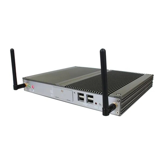
General Information 1.7 Locating Controls and Connectors Please take a moment to identify those controls and connectors shown in the following figures. Front Panel Antenna Antenna USB Ports MIC-in Indicator Switch Earphone-out CFast & SIM Slots Rear Panel DC-IN DVI-D DVI-I COM1-4 USB Ports... -
Page 19: Chapter 2 - The Engine Of Fpc-3130/3130V
Chapter 2 The Engine of FPC-3130/3130V - 9 -... -
Page 20: Board Layout
The Engine of FPC-3130/3130V 2.1. Board Layout The engine of FPC-3130/3130V is FMB-i2505. JACC1 PWRBT1 HDDLED USB2 USB3 DIMM2 SIM1 USB1 LAN1 AUDIO2 AUDIO3 AUDIO4 - 10 -... -
Page 21: Jumpers And Connectors
The Engine of FPC-3130/3130V 2.2. Jumpers and Connectors 2.2.1. Jumpers & Connectors List Jumpers Label Function JBAT1 Clear CMOS Setting JCP1 COM Port Power Selector JV1~4 RI/5V/12V (Pin 9) Selectors for COM1~4 Ports JACC1 Vehicle/Automation Power Mode Selection System On/Off Timing Setting Jumper... -
Page 22: Jumper Setting
The Engine of FPC-3130/3130V 2.2.2. Jumper Setting JBAT1: Clear CMOS Setting Description Keep CMOS (Default) Clear CMOS JCP1: COM Port Power Selector Description Normal (Default) +12V JV1~4: RI/5V/12V (Pin 9) Selection for COM1~4 Ports Description Normal (Default) COMPOWER Note: JV1~4 correspond to COM1~4 ports respectively. - Page 23 The Engine of FPC-3130/3130V SW1 for FPC-3130V: System On/Off Timing Setting Jumper 1 2 3 4 5 6 Description DIP SW Auto Car Key on Detection On, Off (default) Auto Power On (1 - Auto / 0 - Manual) On, Off (default) Auto Power Off (1 - Auto / 0 - Manual) 3 &...
- Page 24 The Engine of FPC-3130/3130V SW1 for FPC-3130: System On/Off Timing Setting Jumper 1 2 3 4 5 6 Description DIP SW Auto Car Key on Detection On, Off (default) Auto Power On (1 - Auto / 0 - Manual) 3 & 4 On, Off (default) Power-on Waiting Time –...
- Page 25 The Engine of FPC-3130/3130V SW2 only for FPC-3130V: Battery Low Setting Jumper 1 2 3 4 Description Battery Low On, Off (default) 24V Standard Battery Voltage ( EX:BUS) On (default), Off 12V Standard Battery Voltage (EX: CAR) On, Off (default)
- Page 26 The Engine of FPC-3130/3130V SW4~5, SW8~11: RS-232/422/485 Mode Selectors for COM3~4 Ports SW4~5 SW8 & 11 RS-232 RS-422 RS-485 RS-232 RS-422 RS-485 (Default) Mode Mode (Default) Mode Mode Note: SW4, 8, 9 control COM3; SW5, 11, 10 control COM4. You must set the same group of switches together for different modes.
-
Page 27: Pin Assignments For Connectors
The Engine of FPC-3130/3130V 2.2.3. Pin Assignments for Connectors LAN1: Dual Ethernet Connectors USB1~3: Double-stacked USB Connectors 1 2 3 4 1 2 3 4 AUDIO2~4: Audio Jack Connectors - 17 -... - Page 28 The Engine of FPC-3130/3130V CN2: RS-232 (COM1~2); RS-232/422/485 (COM3~4) Desc. Desc. Desc. Desc. COM1 COM2 (RS-232) (RS-232) COM3 COM4 (RS-232) (RS-232) - 18 -...
- Page 29 The Engine of FPC-3130/3130V CBL-7100-COM (COM Converter Cable) (optional) 1 to 5 COM converter cable: 4 x DB9 male and 1 x DB9 female connectors Note: CN6 on DB9 Cable Controller is unused. COM1 (RS-232) labelled CN2 on DB9 Cable Controller...
- Page 30 The Engine of FPC-3130/3130V COM2 (RS-232) labelled CN3 on DB9 Cable Controller DB44 Pin DB9 Pin Desc. DB44 Pin DB9 Pin Desc. COM3 (RS-232) labelled CN4 on DB9 Cable Controller DB44 Pin DB9 Pin Desc. DB44 Pin DB9 Pin Desc.
- Page 31 The Engine of FPC-3130/3130V COM3/4 (RS-485) labelled CN4/5 on DB9 Cable Controller DB9 Pin Signal Desc. DB9 Pin Signal Desc. DATA- DATA+ PWRIN1: DC Adapter Power Input Description 1 2 3 VCC 10~28V VCC GND Acc ACC (ignition signal) DVI1: DVI-I...
- Page 32 This page is intentionally left blank. - 22 -...
-
Page 33: Chapter 3 - Installation And Maintenance
Chapter 3 Installation and Maintenance - 23 -... -
Page 34: Memory, Mini-Card & Hdd Installation
Installation and Maintenance 3.1 Memory, Mini-card & HDD Installation FPC-3130/3130V is designed to be modular, slim and lightweight for easier maintenance. The following sections describe simple hardware installations. 3.1.1 Removing Top Cover 1. Carefully place the Box PC on flat surface. Unscrew four screws securing the top cover. -
Page 35: Installing Memory Module
Installation and Maintenance 3.1.2 Installing Memory Module Side notch Latch knob Latch section Latch claw Latch arm Polarizing key To install the Memory module, locate the Memory SO-DIMM slot on the board and perform as below: 1. Adjust the socket polarizing key and the board key to the same direction. 2. -
Page 36: Installing Mini-Card (Optional)
Installation and Maintenance 3.1.3 Installing Mini-card (optional) 1. Locate Mini-card socket. 2. Insert HSUPA module into its slot at a slanted angle. Remember to align the notch with the break on slot. 3. And then, secure two screws to fasten the module. - 26 -... - Page 37 Installation and Maintenance 4. Push the plastic plug outwards to remove it, so that one end of RF cable, which is a SMA connector jack, can penetrate through antenna hole located on front pane. Keep the plastic plug for later use. 5.
- Page 38 Installation and Maintenance 6. Mount a round washer into the SMA connector jack from outside before securing another nut into it. 7. At the end, screw antenna into the SMA connector jack and adjust antenna angle for better signal. - 28 -...
-
Page 39: Installing Hard Disk Drive
Installation and Maintenance 3.1.4 Installing Hard Disk Drive 1. Unscrew HDD bracket from the main board. Fasten HDD on bracket. 2. Insert the bracket into driver bay and secure its four corners. - 29 -... -
Page 40: How To Access Cfast/Sim Card
Installation and Maintenance 3.2 How to Access CFast/SIM Card 1. Make sure you have turned off the power before inserting or ejecting the CFast card (if OS is installed on CFast card). 2. Locate the CFast card door on the front panel. 3. -
Page 41: Wall Mounting (Optional)
Installation and Maintenance 3.3 Wall Mounting (optional) Prepare the wall-mount bracket and a screwdriver for wall mounting. Follow the instructions below: 1. Place the Box PC upside down on a flat surface and locate the 4 rubber foot screws. 2. Unscrew them and separate the screws from the rubber feet. Keep the rubber feet for later use. -
Page 42: Vesa Mounting (Optional)
Installation and Maintenance 3.4 VESA Mounting (Optional) FPC-3130/3130V can be mounted to the rear side of the LCD monitor that is VESA 75/100 compliant. To mount FPC-3130/3130V to your monitor, please prepare the wall-mount bracket, VESA-mount brackets, accompanying screws and a screwdriver. Please follow the instructions as below: 1. - Page 43 Installation and Maintenance 3. With the wall-mount bracket attached, slide FPC-3130/3130V onto the VESA bracket. When the computer is well seated, secure it to the VESA bracket with the accompanying screws. See the figures shown below. - 33 -...
-
Page 44: Din Rail Mounting (Optional)
Installation and Maintenance 3.5 DIN Rail Mounting (optional) Prepare the DIN rail kit and a screwdriver for DIN rail mounting. Follow the instructions below: 1. Place the Box PC upside down on a flat surface and locate the 4 rubber foot screws. -
Page 45: Face-Left/Right Din Rail Mounting
Installation and Maintenance 3.5.1 Face-Left/Right DIN Rail Mounting 1. For panel face-left/right mounting, please secure the two DIN rail clips to the DIN rail bracket according to the illustration. 2. Position the bracket side of the box PC directly in front of the DIN rail. Make sure the DIN rail spring is hooked over the top of the DIN rail. -
Page 46: Face-Up/Down Din Rail Mounting
Installation and Maintenance 3.5.2 Face-Up/Down DIN Rail Mounting 1. For panel face-up/down mounting, please secure the two DIN rail clips to the DIN rail bracket according to the illustration. 2. Position the bracket side of the box PC directly in front of the DIN rail. Make sure the DIN rail spring is hooked over the top of the DIN rail. -
Page 47: Removing The Box Pc From The Din Rail
Installation and Maintenance 3.5.3 Removing the Box PC from the DIN Rail 1. Make sure power is off, and disconnect all cables from the computer. 2. Hold the Box PC with both hands and push downwards. As the clip releases, lift the bottom of Box PC slightly. -
Page 48: Wiring The Dc-Input Power Source
Installation and Maintenance 3.7 Wiring the DC-Input Power Source Warning Only trained and qualified personnel are allowed to install or replace this equipment. Follow the instructions below for connecting the computer to a DC-input power source. 1. Before wiring, make sure the power source is disconnected. 2. -
Page 49: Automation Power Mode For Fpc-3130
By default, JACC1 is open for FPC-3130. Refer to 2.2.2. Jumper Setting on page 3. System Automatic Power ON/OFF Use SW1 to set desired power mode. Refer to SW1 for FPC-3130 under 2.2.2. Jumper Setting on page 4. Battery Low Voltage Protection... - Page 50 This page is intentionally left blank. - 40 -...
-
Page 51: Chapter 4 - Driver & Ap
Chapter 4 Driver & AP - 41 -... -
Page 52: Prior To Installation
Also, the correct driver & AP paths for Windows 7 are listed below. You should follow the suggested paths to proceed with installation. Windows 7-32bit Driver Path CHIPSET \Chipset\Win7_x86 \VGA\Win7_x86 \LAN\Install_Win7_7048_09162011 AUDIO \Driver\Audio ALC662\Win 7(32,64 bits) Driver_R2.66 Note: FPC-3130/3130V only supports Windows 7 32bit. - 42 -... -
Page 53: Drivers
Driver & AP 4.2 Drivers 4.2.1. CHIPSET 1. Run the executable file “infinst_autol.exe” at the folder \Chipset\Win7_x86 as described in 4.1 Prior to Installation on page 42. The installation wizard then opens 2. Select Next to proceed. - 43 -... - Page 54 Driver & AP The installation wizard then starts to extract the files required for the driver installation, which is through in a few seconds. 3. Read the license agreement and click Yes to proceed. - 44 -...
- Page 55 Driver & AP 4. Read the readme file and click Next to proceed. The driver installation then starts and finishes in a few seconds. 5. Click Finish to finish and quit the installation. - 45 -...
-
Page 56: Vga
Driver & AP 4.2.2. VGA 1. Run the executable file “Setup.exe” at the folder \VGA\Win7_x86 as described in 4.1 Prior to Installation on page 42. The installation wizard then opens. 2. Click Next to proceed. - 46 -... - Page 57 Driver & AP 3. Read the license agreement and click Yes to proceed. 4. Read the readme file and click Next to proceed. - 47 -...
- Page 58 Driver & AP The setup operation then starts and progresses. 5. Once the setup operation is through, click Next to proceed. - 48 -...
- Page 59 Driver & AP 6. Select Yes, I want to restart this computer now and press Finish button to restart the computer by the support of the VGA driver you just installed. Select No, I will restart this computer later and press Finish button to finish and quit the driver installation.
-
Page 60: Audio
Driver & AP 4.2.3. Audio 1. Run the executable file “Vista_Win7_R266.exe” at the folder \Audio ALC662\ Win 7(32,64 bits) Driver_R2.66 as described in 4.1 Prior to Installation page 42. File extraction then starts and progresses for the driver installation. - 50 -... - Page 61 Driver & AP 2. Once the file extraction is through, click Next to proceed. The installation wizard proceeds to prepare for the setup. - 51 -...
- Page 62 Driver & AP 3. Once the preparation is through, the installation wizard prompts to install the audio driver. Click Next to proceed. The installation starts and progresses. - 52 -...
- Page 63 Driver & AP 4. Once the installation is through, select Yes, I want to restart my computer now and press Finish button to restart the computer by the support of the audio driver you just installed. Select No, I will restart my computer later and press Finish button to finish the driver installation.
-
Page 64: Lan
Driver & AP 4.2.4. LAN 1. Run the executable file “setup.exe” at the folder \LAN\Install_ Win7_7048_09162011 as described in 4.1 Prior to Installation on page The installation wizard opens and prompts to install the Ethernet controller driver. Click Next to proceed. - 54 -... - Page 65 Driver & AP 2. Click Install to proceed. The installation starts and progresses. - 55 -...
- Page 66 Driver & AP 3. Once the installation is through, select press Finish button to finish and quit the driver installation - 56 -...
-
Page 67: Chapter 5 - Bios
BIOS Chapter 5 BIOS - 57 -... -
Page 68: Bios Main Setup
Data BIOS Vendor American Megatrends elements. Core Version 4.6.5.1 Compliancy UEFI 2.3; PI 1.2 BIOS Version FPC-3130 1.12 Build Date and Time 09/25/2014 10:27:43 System Date [Fri 05/31/2014] System Time [17:31:42] Access Level Administrator →←: Select Screen ↓↑: Select Item... -
Page 69: System Time
BIOS System Time Set the system time. The time format is: Hour : 00 to 23 Minute : 00 to 59 Second : 00 to 59 5.2 Advanced Settings Aptio Setup Utility - Copyright (C) 2011 American Megatrends, Inc. Main Chipset Boot Security Save &... -
Page 70: Acpi Settings
BIOS 5.2.1 ACPI Settings Aptio Setup Utility - Copyright (C) 2011 American Megatrends, Inc. Advanced ACPI Settings Enables or Disables System ability to Enable Hibernation [Enabled] Hibernate (OS/S4 Sleep ACPI Sleep State [S1 (CPU Stop Clock)] State). This option Lock Legacy Resources [Disabled] may be not effective with some OS. -
Page 71: Cpu Configuration
BIOS 5.2.2 CPU Configuration The CPU Configuration setup screen varies depending on the installed processor. Aptio Setup Utility - Copyright (C) 2011 American Megatrends, Inc. Advanced Enabled for Windows XP CPU Configuration and Linux(OS optimized for Hyper-Threading Processor Type Intel(R) Atom(TM) CPU Technology) and EMT64 Supported... -
Page 72: Ide Configuration
BIOS 5.2.3 IDE Configuration It allows you to select the operation mode for SATA controller. Aptio Setup Utility - Copyright (C) 2011 American Megatrends, Inc. Advanced SATA Port0 WDC WD3200BPVT (320.0 SATA Ports (0-3) Device Names if SATA Port1 Not Present Present and Enabled. -
Page 73: Usb Configuration
BIOS 5.2.4 USB Configuration Aptio Setup Utility - Copyright (C) 2011 American Megatrends, Inc. Advanced USB Configuration Enables Legacy USB support. AUTO option disables legacy USB Devices: support if no USB 1 Keyboard devices are connected. DISABLE option will Legacy USB Support [Enabled] keep USB devices EHCI Hand-off... -
Page 74: Super Io Configuration
BIOS 5.2.5 Super IO Configuration Aptio Setup Utility - Copyright (C) 2011 American Megatrends, Inc. Advanced Super IO Configuration Set Parameters of Serial Port 1 (COMA) ► Serial Port 1 Configuration ► Serial Port 2 Configuration ► Serial Port 3 Configuration ►... -
Page 75: H/W Monitor
BIOS Aptio Setup Utility - Copyright (C) 2011 American Megatrends, Inc. Advanced Serial Port 1 Configuration Enable or Disable Serial Port (COM) Serial Port [Enabled] Device Settings IO=3F8h; IRQ=4; Change Settings [Auto] RS485 AutoFlow [Disable] →←: Select Screen ↓↑: Select Item Enter: Select +/-: Change Opt. -
Page 76: Chipset Settings
BIOS 5.3 Chipset Settings This submenu allows you to configure the specific features of the chipset installed on your system. The chipset manage bus speeds and access to system memory resources, such as DRAM. It also coordinates communications with the PCI bus. Note: Beware of that setting inappropriate values in items of this menu may cause system to malfunction. -
Page 77: Memory Frequency And Timing
BIOS Memory Frequency and Timing Aptio Setup Utility - Copyright (C) 2011 American Megatrends, Inc. Chipset Memory Frequency and Timing Enable or disable MRC fast boot. MRC Fast Boot [Enabled] Dyn SR [Enabled] →←: Select Screen ↓↑: Select Item Enter: Select +/-: Change Opt. -
Page 78: South Bridge
BIOS 5.3.2 South Bridge Aptio Setup Utility - Copyright (C) 2011 American Megatrends, Inc. Chipset ► TPT Devices Enable/Disable ► PCI Express Root Port 0 Intel(R) IO Controller [1-2 Seconds] ► PCI Express Root Port 1 Hub (TPT) devices [Power On] ►... - Page 79 BIOS Select USB Mode Select USB mode to control USB ports. UHCI #1~4 (ports 0/2/4/6 and 1/3/5/7) Control the USB UHCI (USB 1.1) functions. Disable from highest to lowest controller. USB 2.0(EHCI) Support Enable/Disable USB 2.0(EHCI) Support. SIRQ Logic Enable/Disable SIRQ Logic. SIRQ Mode Set SIRQ Mode.
-
Page 80: Hot Plug
BIOS Enable/Disable PCI Express Unsupported Request Reporting. Enable/Disable PCI Express Device Fatal Error Reporting. NFER Enable/Disable PCI Express Device Non-Fatal Error Reporting. Enable/Disable PCI Express Device Correctable Error Reporting. Enable/Disable PCI Express Completion Timer TO. SEFE Enable/Disable Root PCI Express System Error on Fatal Error. SENFE Enable/Disable Root PCI Express System Error on Non-Fatal Error. -
Page 81: Boot Settings
BIOS 5.4 Boot Settings The Boot menu items allow you to change the system boot options. Aptio Setup Utility - Copyright (C) 2011 American Megatrends, Inc. Main Advanced Chipset Security Save & Exit Boot Select the Keyboard Boot Configuration NumLock state [On] Bootup NumLock State [Disabled]... -
Page 82: Security
BIOS 5.5 Security Aptio Setup Utility - Copyright (C) 2011 American Megatrends, Inc. Main Advanced Chipset Boot Security Save & Exit Set Administrator Password Description Password The password length must be in the following range: Minimum length Maximum length Administrator Password →←: Select Screen ↓↑: Select Item Enter: Select... -
Page 83: Save & Exit
BIOS You can determine when the password is required within the BIOS Features Setup Menu and its Security option. If the Security option is set to “System”, the password will be required both at boot and at entry to Setup. If it’s set to “Setup”, prompting only occurs when trying to enter Setup. -
Page 84: Boot Override
BIOS Restore Defaults Restore system to settings previously stored by Save as User Defaults. Pressing <Enter> on this item and it asks for confirmation prior to executing this command. Boot Override This group of functions includes a list of tokens, each of them corresponding to one device within the boot order. -
Page 85: Appendix
Appendix - 75 -... -
Page 86: Watchdog Timer (Wdt) Setting
Appendix Watchdog Timer (WDT) Setting WDT is widely applied to industry computers to monitor activities of CPU. The programmed application triggers WDT with adequate timer setting depending on its requirement. Before WDT counts down to zero, the functional system will reset the counter. In case the WDT counter is not reset by an abnormal system, it will counts down to zero and then reset the system automatically.
Need help?
Do you have a question about the FPC-3130 and is the answer not in the manual?
Questions and answers