
Subscribe to Our Youtube Channel
Related Manuals for Arbor Technology ARES-1983H Series


Summary of Contents for Arbor Technology ARES-1983H Series
- Page 1 ARES-1983H Series Compact Embedded Computer with Intel Gen. Core™ i7/i5/i3 Processor ® User’s Manual Version 1.0 P/N: 4016198300100P 2023.09...
- Page 2 Revision History Version Date Description 2023.09 Initial release - II -...
-
Page 3: Table Of Contents
Contents Contents Revision History ................II Contents ....................i Preface....................iii Copyright Notice ..................iii Declaration of Conformity ...............iii CE ....................iii FCC Class A ..................iii RoHS ....................iv SVHC / REACH ................iv Important Safety Instructions ..............v Warning ....................vi Lithium Battery Replacement ..............vi Technical Support .................. -
Page 4: Contents
Contents 4.2.4. Installing a M.2 Module ............31 4.2.5. Installing WI-FI connection module and antenna ....33 4.2.6. Installing a SIM Card and relative connection module ..36 4.3. Mounting ..................38 4.3.1. Wall Mounting ..............38 4.3.2. DIN-Rail Mounting ............... 39 Chapter 5 - BIOS ................41 5.1. -
Page 5: Preface
Preface Copyright Notice All Rights Reserved. The information in this document is subject to change without prior notice in order to improve the reliability, design and function. It does not represent a commitment on the part of the manufacturer. Under no circumstances will the manufacturer be liable for any direct, indirect, special, incidental, or consequential damages arising from the use or inability to use the product or documentation, even if advised of the possibility of such damages. -
Page 6: Rohs
(PBDE) in electrical and electronic products. Member states of the EU are to enforce by 7/1/2006. ARBOR Technology Corp. hereby states that the listed products do not contain unintentional additions of lead, mercury, hex chrome, PBB or PBDB that exceed a maximum concentration value of 0.1% by weight or for cadmium... -
Page 7: Important Safety Instructions
Preface Important Safety Instructions Read these safety instructions carefully 1. Read all cautions and warnings on the equipment. 2. Place this equipment on a reliable surface when installing. Dropping it or letting it fall may cause damage 3. Make sure the correct voltage is connected to the equipment. 4. -
Page 8: Warning
Preface Warning The Box PC and its components contain very delicately Integrated Circuits (IC). To protect the Box PC and its components against damage caused by static electricity, you should always follow the precautions below when handling it: 1. Disconnect your Box PC from the power source when you want to work on the inside. -
Page 9: Warranty
Preface Warranty This product is warranted to be in good working order for a period of one year from the date of purchase. Should this product fail to be in good working order at any time during this period, we will, at our option, replace or repair it at no additional charge except as set forth in the following terms. - Page 10 This page is intentionally left blank. - viii -...
-
Page 11: Chapter 1 - Introduction
Chapter 1 Introduction Chapter 1 - Introduction - 1 -... -
Page 12: Features
We recommend that you keep one copy of this manual for the quick reference for any necessary maintenance in the future. Thank you for choosing ARBOR products. The ARES-1983H series includes the following models: Outlook Description ARES-1983 w/ H610E Chipset, 3 x LAN, 2 x COM, ARES-1983H 6 x USB, 1 x DP, 1 x VGA, 1 x M.2 E-Key, 1 x mPCIe... -
Page 13: Specifications
Introduction 1.3. Specifications System ® Intel 12th/13th Core™ i7/i5/i3 processor in LGA1700 Socket (Max.65W) 1 x 262-pin DDR5 SO-DIMM sockets, Memory supporting 5600MHz SDRAM up to 32GB ® Intel H610E Chipset Graphics Integrated Intel UHD Graphics 730/770 ® 1 x Intel i226LM ®... - Page 14 Introduction Storage 1 x M.2 M-key 2242/2280 slot (PCIe 4.0 x4 + SATA) Type 1 x 2.5” HDD/SSD internal drive bay (For ARES-1983H-MV) Environmental w/ 35W TDP CPU: -20 ~ 60°C, ambient w/ air flow Operating Temp. w/ 65W TDP CPU: -20 ~ 50°C, ambient w/ air flow Storage Temp.
-
Page 15: Inside The Package
Introduction 1.4. Inside the Package Upon opening the package, carefully inspect the contents. If any of the items is missing or appears damaged, contact your local dealer or distributor. The package should contain the following items: 1 x ARES-1983H / ARES-1983H-MV ARES-1983H 1 x Accessory Box that contains the following items:... - Page 16 This page is intentionally left blank. - 6 -...
-
Page 17: Chapter 2 - Getting Started
Chapter 2 Getting Started Chapter 2 - Getting Started - 7 -... -
Page 18: Dimensions
Getting Started 2.1. Dimensions ARES-1983H 63.00 164.00 55.00 24.00 for din rail mounting 4-M34mm 4- 3.40 Unit: mm ARES-1983H-MV 98.00 164.00 90.00 24.00 for din rail mounting 4-M34mm 4- 3.40 Unit: mm - 8 -... -
Page 19: Overview
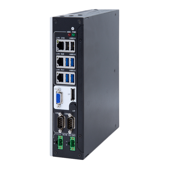
Getting Started 2.2. Overview 2.2.1. Front View (ARES-1983-MV) USB 2.0 Ports Power Button PoE Ports 2.5GbE LAN Port USB 3.2 Gen1 (5Gbps) GbE LAN Port USB 3.2 Gen2 (10Gbps) Display Port VGA Port Remote on/off Switch RS-232 Port DI/O Port RS-232/422/485 Port DC In DC In... - Page 20 Getting Started DC In Connector Connector Type: 2.54mm pitch 2-pin terminal Block Pin Assignment: Pin Description DC in (+) Ground (-) Note: Please note that one DC in is enough to power up the device. Select either one for DC input and the other one could be output to provide additional power. COM Connector Connector Type: 9-pin D-sub Male Connector Pin Assignment:...
-
Page 21: Led Indicator Status
Getting Started 2.2.2. LED Indicator Status Color Description Indicator Green Solid: The system is in operation(S0) PWR Button Solid: The system is in in sleep/hibernate mode(S3/S4) or power off mode(S5) PWR LED Solid Green Solid: The system is powered on SATA HDD/SSD Flashing: Data is transmitting Solid: Link is established... -
Page 22: Driver Installation Note
Getting Started 2.3. Driver Installation Note For operating system of Windows 10, please go to our website at www.arbor-technology.com and download the driver pack from the product page. Then unzip the downloaded file and follow the sequence below to install the drivers to prevent errors: Chipset →... -
Page 23: Chapter 3 - Engine Of The Computer
Chapter 3 Engine of the Computer Chapter 3 - Engine of the Computer - 13 -... -
Page 24: Main Board - Fmb-I93Q0
Engine of the Computer 3.1. Main Board - FMB-i93Q0 Top: Bottom: ⑨ COM3 ⑩ COM4 ⑭ MMC1 ⑪ MEKEY1 ⑫ MC1 ⑬ SIM1 ⑮⑯ ETX Connector - 14 -... -
Page 25: Jumper & Connectors
Engine of the Computer 3.1.1. Jumper & Connectors Jumper Label Description ❶ JCMOS1 Clear CMOS Jumper Connectors Label Description ① CPUFAN1 System Fan Connector ② USB1/USB2 USB 2.0 Type-A Connector ③ SATA1 SATA 7-pin Connector ④ PWROUT1 SATA Power Connector ⑤... -
Page 26: Jumper & Connectors Settings
Engine of the Computer 3.1.2. Jumper & Connectors Settings ❶ JCMOS1 Function: Clear CMOS Selection Jumper Type: 2.00mm pitch 2-pin Header Cond. Description Setting: Short Clear CMOS Open Keep CMOS (default) ① CPUFAN1 Function: Fan Power Connector Connector Type: 2.54mm pitch 4-pin Wafer Description Pin Assignment: +12V... - Page 27 Engine of the Computer ④ PWROUT1 Function: SATA Power Connector Connector Type: 2.54mm pitch 4-pin Wafer Description Pin Assignment: +12V ⑤ DGP1 Function: Debug Port Connector Type: 2.00mm pitch 10-pin Header Description Description Pin Assignment: ESPI_CLK ESPI_CS0# ESPI_IO0 ESPI_RST# V3.3A ESPI_IO3 ESPI_IO2 V3.3S...
- Page 28 Engine of the Computer ⑧ SW1 Function: Remote Control Connector Type: 2-pin Header(S2B-PH-K-S) Description Pin Assignment: PWR_IN_SW# ⑨ COM3 Function: RS-232/RS-422/RS-485 Serial Port Header Connector Type: 2.00mm pitch 9-pin Header RS-232 RS-422 RS-485 Pin Assignment: COM_422 TX- COM_485 D- COM_422 TX+ COM_485 D+ COM_422 RX+ COM_422 RX-...
- Page 29 Engine of the Computer ⑪ MEKEY1 M.2 E-Key Socket (w/ PCIe 3.0 x1 + USB 2.0) for Wi-Fi/ Function: Connector Type: M.2 E-Key 2230 Socket Pin Assignment: The pin assignments conform to the industry standard. ⑫ MC1 Function: Full-size mini PCI-e Socket (w/ PCIe 3.0 x1 + USB 2.0) Connector Type: Mini PCI-e 52-pin Socket Pin Assignment: The pin assignments conform to the industry standard.
-
Page 30: Daughter Board - Scdb-348D (For Ares-1983H-Mv)
Engine of the Computer 3.2. Daughter Board - SCDB-348D (For ARES-1983H-MV) Function: PoE and isolated digital I/O daughter board Applicable models: ARES-1983H-MV Top: ① LCN1~LCN4 Bottom ③④ ETX Connector - 20 -... -
Page 31: Connectors Settings
Engine of the Computer 3.2.1. Connectors Settings ① LCN1~LCN4 Function: 1GbE PoE (IEEE 802.3af) Connector Type: RJ-45 Connector Pin Assignment: The pin assignments conform to the industry standard. ② DIO Function: Digital Input & Output Connector Type: 38-pin Terminal Block Pin Assignment: Description Description... - Page 32 This page is intentionally left blank. - 22 -...
-
Page 33: Chapter 4 - Installation And Maintenance
Chapter 4 Installation & Maintenance Chapter 4 - Installation and Maintenance - 23 -... -
Page 34: Disassembling And Assembling The Computer
Installation & Maintenance 4.1. Disassembling and Assembling the Computer 4.1.1 Disassembling the Computer (ARES-1983H) To use onboard jumpers/connectors or to install/remove internal components, you will need to open the computer to access the inside of the computer. Follow through the guide below to disassemble the computer. - 24 -... -
Page 35: Disassembling The Computer (Ares-1983H-Mv)
Installation & Maintenance 4.1.2. Disassembling the Computer (ARES-1983H-MV) To use onboard jumpers/connectors or to install/remove internal components, you will need to open the computer to access the inside of the computer. Follow through the guide below to disassemble the computer. - 25 -... -
Page 36: Assembling The Computer
Installation & Maintenance Bottom side of the main board Top side of the main board 4.1.3. Assembling the Computer After completing the required hardware installation and jumpers settings, assemble the computer as above figure. - 26 -... -
Page 37: Installing Hardware
Installation & Maintenance 4.2. Installing Hardware 4.2.1. Installing CPU 1. Remove the top and side cover from the computer as described in 4.1. Disassembling and Assembling the Computer on page 24 2. Locate the CPU socket on the main board The processor socket comes with a mylar sticker to secure the processor. -
Page 38: Installing Memory Module
Installation & Maintenance 4.2.2. Installing Memory Module 1. Remove the top cover from the computer as described in 4.1. Disassembling and Assembling the Computer on page 24 2. Locate the SO-DIMM sockets on the main board. The SO-DIMM sockets are vertical type, and each socket has two latches for fixing the memory modules. - Page 39 Installation & Maintenance 6. Align the notch on the memory module with the key in the module socket. 7. Vertically plug the memory module to the DIMM socket. “Fully” plug the memory module until both latches auto-lock the memory module in place. - 29 -...
-
Page 40: Installing A 2.5" Ssd Or Hdd
Installation & Maintenance 4.2.3. Installing a 2.5" SSD or HDD 1. Remove the bottom cover from the computer as described in 4.1.2. Disassembling the Computer (ARES-1983H-MV) on page 2. Using 4 x M3*4 screws coming with the storage device kit to install a 2.5”... -
Page 41: Installing A M.2 Module
Installation & Maintenance 4.2.4. Installing a M.2 Module The computer has a M.2 M-Key socket for NVMe or SATA SSD. This section will use a 22 x 80 form factor as the installation example. 1. Remove the bottom cover from the computer as described in 4.1. - Page 42 Installation & Maintenance 2. Insert the M.2 module into the socket by aligning the notch on the module with the small slot on the M.2 socket. 3. Insert and fasten the screw into the standoff. - 32 -...
-
Page 43: Installing Wi-Fi Connection Module And Antenna
Installation & Maintenance 4.2.5. Installing WI-FI connection module and antenna 1. Remove the bottom cover from the computer as described in 4.1.2. Disassembling the Computer (ARES-1983H-MV) on page 25. 2. Locate the M.2 E-Key socket for wireless module. 3. Prepare the Wi-Fi module kit. The module is a M.2 E-Key socket form factor, with two MHF connectors, one is “MAIN“, and the other is “AUX“. - Page 44 Installation & Maintenance 5. Connect the RF antenna’s MHF connector to the Wi-Fi module’s main connector marked 0. If you are going to connect a secondary antenna, connect it to the connector marked Connect the RF antenna’s MHF connector to the Wi-Fi module’s main connector (marked 2) Connect the secondary RF...
- Page 45 Installation & Maintenance 8. From the other end of the RF antenna, which is an SMA connector, remove the washer and the nut. Note the SMA connector has the form of a threaded bolt, with one flat side. Among the screw Remove thread, there is a the nut and...
-
Page 46: Installing A Sim Card And Relative Connection Module
Installation & Maintenance 4.2.6. Installing a SIM Card and relative connection module This section will guide you how to install a SIM card and relative connection module. 1. Remove the bottom cover from the computer as described in 4.1.2. Disassembling the Computer (ARES-1983H-MV) on page 25. 2. - Page 47 Installation & Maintenance Insert the SIM card into the card holder as shown below. 5. Close the SIM card holder door and slide the door to the LOCK edge to lock into place. 6. Locate the MC1 slot and insert the relative communication module then fasten the screw.
-
Page 48: Mounting
Installation & Maintenance 4.3. Mounting 4.3.1. Wall Mounting To wall mount the computer using the provided wall-mount kit: 1. Select a proper mounting location with adequate wall strength to support the mounted unit. 2. Locate the 6 screw holes on the computer's rear side. Use the screws (M3x4L, qty:6) included in the wall-mount kit to assemble the brackets to the computer’s rear side. -
Page 49: Din-Rail Mounting
Installation & Maintenance 4.3.2. DIN-Rail Mounting To mount the computer using the optional DIN-rail mounting kit: 1. Select a proper mounting location with adequate wall strength to support the mounted unit. 2. Screw the DIN-rail mounting clip with included screws (M3x5mm, qty:4) to the rear side of the computer as below. - Page 50 Installation & Maintenance After you screw the DIN-rail mounting clip to the computer: 1. Snap the DIN Rail clip to the lower edge of the DIN Rail. 2. Press the computer firmly upward towards the DIN Rail until the DIN Rail clip tab engages and snaps to the upper edge of the DIN Rail.
-
Page 51: Chapter 5 - Bios
Chapter 5 BIOS Chapter 5 - BIOS - 41 -... - Page 52 BIOS The BIOS Setup utility is featured by American Megatrends Inc to configure the system settings stored in the system’s BIOS ROM. The BIOS is activated once the computer powers on. When the computer is off, the battery on the main board supplies power to BIOS RAM.
- Page 53 BIOS Key Commands The BIOS Setup utility relies on a keyboard to receive user’s instructions. Hit the following keys to navigate within the utility and use the utility. Keystroke Function ← → Moves left/right between the top menus. ↓ ↑ Moves up/down between highlight items.
-
Page 54: Main
BIOS 5.1. Main The Main menu features the settings of System Date and System Time and displays some BIOS info. Note: Actual model name and board information varies according to your model. Setting Description Project Version Delivers the model name of the computer and BIOS version. Build Date and Time Delivers the date and time when the BIOS Setup utility was made/ updated. -
Page 55: Advanced
BIOS 5.2. Advanced Setting Description CPU Configuration 5.2.1. CPU Configuration on page 46 Power & Performance 5.2.2. Power & Performance on page 47 PCH-FW Configuration 5.2.3. PCH-FW Configuration on page 50 Trusted Computing 5.2.4. Trusted Computing on page 51 ACPI Settings 5.2.5. -
Page 56: Cpu Configuration
BIOS 5.2.1. CPU Configuration Setting Description Efficient-core Information Display the E-core Information Performance-core Information Display the P-core information When enabled, a VMM can utilize the additional hardware Intel (VMX) Virtualization capabilities provided by Vanderpool Technology Technology ► Options: Enabled (default) or Disabled Number of cores to enable in each processor package. -
Page 57: Power & Performance
BIOS 5.2.2. Power & Performance Setting Description Configure CPU Power Management CPU - Power Management Control on page 5.2.2.1. CPU - Power Management Control Configure graphics processors Power Management GT - Power Management Control on page 5.2.2.2. GT - Power Management Control - 47 -... - Page 58 BIOS 5.2.2.1. CPU - Power Management Control Setting Description Set the performance state that the BIOS will set before the OS handoff. Boot performance Mode ► Options: Max Non-Turbo Performance (default), Max Battery and Turbo Performance Intel (R) Speed Step (tm) Enable (default) / Disable Intel SpeedStep C States Enable / Disable (default) CPU C States...
- Page 59 BIOS 5.2.2.2. GT - Power Management Control Setting Description Function of activation and deactivation the energy-saving mechanism integrated into the Intel graphics core processors RC6 (Render Standby) when the computer enters sleep mode. Enable (default) / Disable This item maximum GT frequency limited by te user. Value beyond the range will be clipped to min/max supported by SKU.
-
Page 60: Pch-Fw Configuration
BIOS 5.2.3. PCH-FW Configuration Setting Description Select TPM device: PTT or dPTM. PTT - Enables PTT in SKuMgr dTPM1.2 - Disables PTT in SKuMgr Warning! PTT/dTPM will be PTT Configuration disabled and all data saved on it will be lost. Options: dTPM (default) / PTT - 50 -... -
Page 61: Trusted Computing
BIOS 5.2.4. Trusted Computing Setting Description This item enables or disables BIOS support for security device. OS will not show Security Device. Security Device Support Enabled (Default) / Disabled Enables or disables SHA-1 PCR Bank. SHA256 PCR Bank Enabled (Default) / Disabled This item schedule an operation for the security device. - Page 62 BIOS This item select to tell O.S. to support PPI Spec Version 1.2 or Physical Presence Spec 1.3. Version Options are: 1.3 (Default) / 1.2 TPM 1.2 will restruct support to TPM 1.2 devices, TPM 2.0 will restrict support to TPM 2.0 devices, Auto will support both TPM Device Select 2.0 devices and TPM 1.2 deviced.
-
Page 63: Acpi Settings
BIOS 5.2.5. ACPI Settings Setting Description Enable (default) or Disable system ability to Hibernate (OS/ Enable Hibernation S4 Sleep State). This option may not be effective with some operating system. Only available when BIOS ACPI Auto Configuration is enabled. Select ACPI sleep state the system will enter when the ACPI Sleep State SUSPEND button is pressed. -
Page 64: F81966 Super Io Configuration
BIOS 5.2.6. F81966 Super IO Configuration Note: The quantity of serial ports varies according to your model. - 54 -... - Page 65 BIOS Setting Description To configure each COM port settings. Serial Port 1: ► Options: Enable and Disable Serial Port (COM) (default) Serial Port2: ► Options: Enable and Disable Serial Port (COM) (default) ► Options: Mode Select for RS-232 (default) RS-422, RS- 422(Termination Resistor), RS-485, RS-485(Termination Resistor) Serial Port3:...
-
Page 66: Hardware Monitor
BIOS 5.2.7. Hardware Monitor Access this submenu to monitor the hardware status. Setting Description Enable or Disable Fan1 Output Mode Selection. Smart Fan ► Fan Mode Options available are: Function Auto - Duty Cycle (default) Manual - Duty Cycle - 56 -... -
Page 67: S5 Rtc Wake Settings
BIOS 5.2.8. S5 RTC Wake Settings Setting Description Enable or Disable (default) system wake on alarm event. ► Options available are: Wake System Disabled (default): from S5 Fixed Time: System will wake on the hr::min::sec specified. DynamicTime: If selected, you need to set Wake up minute increase from 1 - 5. -
Page 68: Serial Port Console Redirection
BIOS 5.2.9. Serial Port Console Redirection Setting Description Console Redirection Console Redirection Enalble or Disable - 58 -... -
Page 69: Ami
BIOS 5.2.10. AMI The features settings are: Setting Description Output Select Output select - 59 -... -
Page 70: Usb Configuration
BIOS 5.2.11. USB Configuration Setting Description Enables/disables legacy USB support. ► Options available are Enabled (default), Disabled and Auto. ► Select Auto to disable legacy support if no USB device are Legacy USB Support connected. ► Select Disabled to keep USB devices available only for EFI applications. - Page 71 BIOS USB hardware delay and time-out Use this item to set the time-out value for control, bulk, and interrupt USB transfer time- transfers. Options: 1 sec, 5 sec, 10 sec, 20 sec ► (default) Use this item to set USB mass storage device start unit command time- Device reset time- out.
-
Page 72: Network Stack Configuration
BIOS 5.2.12. Network Stack Configuration Setting Description Network Stack Enable or Disable (default) UEFI network stack. - 62 -... -
Page 73: Nvme Configuration
BIOS 5.2.13. NVMe Configuration Access this submenu to view the NVMe controller and driver information. - 63 -... -
Page 74: Chipset
BIOS 5.3. Chipset Submenu Description System Agent (SA) Configuration See 5.3.1. System Agent (SA) Configuration on page 65 PCH-IO Configuration 5.3.1.3 VMD Configuration on page 68 - 64 -... -
Page 75: System Agent (Sa) Configuration
BIOS 5.3.1. System Agent (SA) Configuration Submenu Description System Agent (SA) Configuration Memory Configuration 5.3.1.1. Memory Configuration on page 66 Graphics Configuration 5.3.1.2. Graphics Configuration on page 67 VMD setup menu Enabled (default) or Disabled to VMD controller VT-d Enabled (default) or Disabled VT-d function - 65 -... - Page 76 BIOS 5.3.1.1. Memory Configuration Access this submenu to view the memory configuration. - 66 -...
- Page 77 BIOS 5.3.1.2. Graphics Configuration Note: This page varies according to your model. Setting Description Graphics Turbo IMON Current Graphics turbo IMON current values supported(14-31) Select which of IGFX/PEG/PCI Graphics device should be Primary Display or select HG for Hybrid GFX. Primary Display Options: Auto, IGFX, PEG Slot, PCH PCI, HG Select the Aperture Size...
- Page 78 BIOS 5.3.1.3 VMD Configuration Setting Description Enablee/Disable to VMD controller Enable VMD controller Options: Enabled, Disabled(default). ► - 68 -...
- Page 79 BIOS 5.3.1.4 VT-d Setting Description Enablee/Disable VT-d capability VT-d ► Options: Enabled (default), Disabled. - 69 -...
-
Page 80: Pch-Io Configuration
BIOS 5.3.2. PCH-IO Configuration Setting Description PCI Express Configuration 5.3.2.1. PCI Express Configuration on page 71 SATA Configuration 5.3.2.2. SATA Configuration on page 72 Enable/Disable onboard NIC. PCH LAN Controller ► Options are: Enabled (default), Disabled. - 70 -... - Page 81 BIOS 5.3.2.1. PCI Express Configuration Setting Description POE LAN 1-4: Control the PCI Express Root Port. ► Options are: Enabled (default), Disabled. ASPM: Set the ASPM level ► Options are: Disabled (default), L1, Auto POE LAN1 - 4 L1 Substates: PCI Express L1 Substates settings. ►...
- Page 82 BIOS 5.3.2.2. SATA Configuration Setting Description Enables (default) / disables SATA device(s). SATA Controller(s) SATA device information. Serial ATA Port 0/1 *Available SATA ports depend on your device. Enables (default) / disables the SATA port. Port 0/1 Enables / disables (default) the SATA port DevSlp. Board SATA Port 0/1 DevSlp rework for LP needed before enable.
-
Page 83: Security
BIOS 5.4. Security Setting Description To set up an administrator password: Select Administrator Password. Administrator An Create New Password dialog then pops up onscreen. Password Enter your desired password that is no less than 3 characters and no more than 20 characters. Hit [Enter] key to submit. -
Page 84: Security Boot
BIOS 5.4.1 Security Boot Setting Description Enabled/Disabled (default) secure boot. Secure Boot Allow users to set the secure boot selector. Secure Boot Mode Options are: Standard/Custome (default) mode. Restore Factory Force system to restore default secure boot key database. Keys Reset to Setup Delete all secure boot key databases. -
Page 85: Boot
BIOS 5.5. Boot Setting Description Set how long to wait for the prompt to show for entering BIOS Setup. Setup Prompt Timeout ► The default setting is 1 (sec). ► Set it to 65535 to wait indefinitely. Sets whether to enable or disable the keyboard’s NumLock state when the system starts up. -
Page 86: Save & Exit
BIOS 5.6. Save & Exit Setting Description Save Changes Saves the changes and quits the BIOS Setup utility. and Exit Restores all settings to defaults. Restore Defaults ► This is a command to launch an action from the BIOS Setup utility. Boot Override presents a list in context with the boot devices in the system. -
Page 87: Appendix
Appendix Appendix - 77 -... -
Page 88: Appendix A. 16-Bit Opto-Isolated Di Signal Connections
Appendix Appendix A. 16-bit Opto-Isolated DI Signal Connections A.1. Wet Contact DI with NPN / PNP connection Digital Input - Wet Contact Max. 3V 12~24V 12~24VDC DI15 12~24VDC DI15 - 78 -... -
Page 89: Dry Contact Di With Npn / Pnp Connection
Appendix A.2. Dry Contact DI with NPN / PNP connection +24V DI15 +24V DI15 - 79 -... -
Page 90: Appendix B. 16-Bit Opto-Isolated Do Signal Connections
Appendix Appendix B. 16-bit Opto-Isolated DO Signal Connections B.1. DO Connection diagram When an isolated output channel is being used as an output channel, if an external voltage (maximum 24V) is applied, the current will flow from the external voltage source to the system. Make sure that the current through each out pin does not exceed 100 mA.
Need help?
Do you have a question about the ARES-1983H Series and is the answer not in the manual?
Questions and answers