
Subscribe to Our Youtube Channel
Related Manuals for Arbor Technology FPC-821 Series


Summary of Contents for Arbor Technology FPC-821 Series
- Page 1 FPC-821X Series Robust Box PC with Intel Gen Core ® i9/i7/i5/i3 Processor User’s Manual Version 1.0 P/N: 4016821200100P 2024.02...
- Page 2 This page is intentionally left blank. - 2 -...
- Page 3 Revision History Version Release Time Description 2024.02 Initial release - i -...
-
Page 4: Table Of Contents
Contents Contents Revision History ................i Contents ..................ii Preface.................... v Copyright Notice.................. v Declaration of Conformity..............v CE ....................v FCC Class A ................v RoHS ...................vi SVHC / REACH ................vi Important Safety Instructions .............vii Warning .....................viii Replacing Lithium Battery ..............viii Technical Support................viii Warranty ....................ix Chapter 1 - Introduction .............. -
Page 5: Contents
Contents 4.2. Wire DC-in Power Source ............43 4.2.1 Automation Mode ............. 43 4.3 Replace RTC Battery ..............44 Chapter 5 - BIOS ................45 5.1. Main ................... 48 5.2. Advanced ................... 49 5.2.1. CPU Configuration ............50 5.2.2. Power & Performance ............. 51 5.2.3. - Page 6 This page is intentionally left blank. - iv -...
-
Page 7: Preface
Preface Preface Copyright Notice All Rights Reserved. The information in this document is subject to change without prior notice in order to improve the reliability, design and function. It does not represent a commitment on the part of the manufacturer. Under no circumstances will the manufacturer be liable for any direct, indirect, special, incidental, or consequential damages arising from the use or inability to use the product or documentation, even if advised of the possibility of such... -
Page 8: Rohs
(PBDE) in electrical and electronic products. Member states of the EU are to enforce by 7/1/2006. ARBOR Technology Corp. hereby states that the listed products do not contain unintentional additions of lead, mercury, hex chrome, PBB or PBDB that exceed a maximum concentration value of 0.1% by weight or for cadmium exceed... -
Page 9: Important Safety Instructions
Preface Important Safety Instructions Read these safety instructions carefully Read all cautions and warnings on the equipment. Place this equipment on a reliable surface when installing. Dropping it or letting it fall may cause damage Make sure the correct voltage is connected to the equipment. For pluggable equipment, the socket outlet should be near the equipment and should be easily accessible. -
Page 10: Warning
Preface Warning The Box PC and its components contain very delicately Integrated Circuits (IC). To protect the Box PC and its components against damage caused by static electricity, you should always follow the precautions below when handling it: Disconnect your Box PC from the power source when you want to work on the inside. -
Page 11: Warranty
Preface Warranty This product is warranted to be in good working order for a period of one year from the date of purchase. Should this product fail to be in good working order at any time during this period, we will, at our option, replace or repair it at no additional charge except as set forth in the following terms. - Page 12 This page is intentionally left blank. - x -...
-
Page 13: Chapter 1 - Introduction
Chapter 1 Introduction Chapter 1 - Introduction - 1 -... -
Page 14: The Computer
Introduction 1.1. The Computer FPC-821X_Series • Fanless Design • Wide Range DC Power Input (9 ~36V) • Various Video Interfaces (VGA + DVI-D+DP) • TPM2.0 support • Optional Wi-Fi6 or LTE/5G Wireless Connectivity • Rugged Design for Shock/Vibration Protection • Memory support up to 64GB - 2 -... -
Page 15: Specifications
Introduction 1.2. Specifications FPC-821X_Series System Intel Gen. Core™ i9/i7/i5/i3 processor in LGA1700 socket ® 2 x 260-pin DDR4 SO-DIMM sockets, Memory supporting 3200 MHz SDRAM up to 64GB Chipset Intel H610E ® Graphics Integrated Intel HD Graphics ® 2 x Serial ATA ports with 600MB/s HDD transfer rate LAN Chipset 3 x Intel WGI226V 2.5GbE controllers... - Page 16 Introduction Environmental -20 ~ 70°C (-4 ~ 158°F), ambient w/ air flow (w/ 35W TDP CPU, fanless) Operating Temp. -20 ~ 55°C (-4 ~ 131°F), ambient w/ air flow (w/ 65W TDP CPU, fanless) Storage Temp. -40 ~ 85°C (-40 ~ 185°F) Operating 10 ~ 95% @ 55°C (non-condensing) Humidity...
-
Page 17: Inside The Package
Introduction 1.3. Inside the Package Upon opening the package, carefully inspect the contents. If any of the items is missing or appears damaged, contact your local dealer or distributor. The package should contain the following items: 1 x FPC-821X Series Robust System 1 x User’s Manual 1.4.1. -
Page 18: Optional Configuration (Ctos* Kit)
Introduction 1.4.2. Optional Configuration (CTOS* Kit) Make the computer more tailored to your needs by selecting one or more components from the list below to be fabricated to the computer. 240GB SSD Intel 2.5” 240GB SATAIII SSD kit ® MK-4C- DDR4-3200 8GB/16GB/32GB SDRAM DIMM kit 4G/8G/16G/32G Intel AX200NGW M.2 Wi-Fi 6 module w/ 2 x 30cm internal... -
Page 19: Chapter 2 - System Overview
Chapter 2 System Overview Chapter 2 - System Overview - 7 -... -
Page 20: Dimensions
System Overview 2.1. Dimensions FPC-821X_Series 4.00 NUT UNC#6-32 6.00 125.20 92.00 92.00 112.00 112.00 268.00 - 8 -... -
Page 21: Take A Tour
System Overview 2.2. Take A Tour 2.2.1. FPC-821X_Series Rear View DB25 Connector / LPT port Fan Connector Line-out Mic-in RS-232 Serial Ports Main Power Input PCI/PCIe slots VGA Port DVI-D Port - 9 -... -
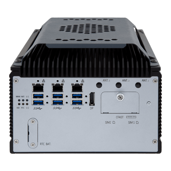
Page 22: Fpc-821X_Series Front View
System Overview 2.2.2. FPC-821X_Series Front View LAN Ports Antenna hole USB 3.2 Gen2 Power button CFast Socket / SIM card Socket RTC Battery USB 3.2 Gen1 Display Port - 10 -... -
Page 23: Driver Installation Notes
2.3. Driver Installation Notes The CPU module supports Windows 10 64-bit and Linux. To install the drivers, please go to our website at www.arbor-technology.com and download the driver pack from the product page. Then extract the down- loaded file and follow the sequence below to install the drivers: Chipset →... - Page 24 This page is intentionally left blank. - 12 -...
-
Page 25: Chapter 3 - System Configuration
Chapter 3 System Configuration Chapter 3 - System Configuration - 13 -... -
Page 26: Board Layout
Engine of the Computer 3.1. Board Layout Board Top ⑮CF1 ⑯DP1 ⑰LANCN1,2,3 ①MC1 JSATA1 JSATA2 ②DGP1 JCMOS1 RSTSW1 JDIO1 ③MEKEY1 ⑭CPUFAN1(2) ④LPT1 ⑬SYSFAN1(2) ⑤DIO1 ⑥MBKEY1 ⑦AUDIO1 AUDIO1 PWRIN1 DVI1 VGA1 ⑫PWRIN1 ⑪VGA1 ⑩DVI1 ⑨COM3, 4 ⑧COM1, 2 - 14 -... - Page 27 Engine of the Computer Board Bottom ⑱SIM1,2 SIM2 SIM1 BAT1 ⑲ PWROUT1,2 PCIE2 ⑳SATA1,2 USBCN1,2 PCIE1 VGACARDPWR1 VGACARDPWR1 COM3 COM4 COM3,4 - 15 -...
- Page 28 Engine of the Computer Jumpers Label Description ➊ SATA mode JSATA1 ➋ SATA mode JSATA2 ➌ Clear CMOS selection JCMOS1 ➍ Reset Button RSTSW1 ➎ VCC_DIO (5V/12V) JDIO1 Connectors Label Description ① PCI Express Mini-card socket ② Onboard 10-pin header DGP1 ③...
- Page 29 Engine of the Computer VGA card power VGACARDPWR1 RS-232 Serial Port (Optional) COM3, COM4 PCI x16 expansion Slot PCIE1 USB 2.0 connectors USBCN1,2 PCI x4 expansion Slot PCIE2 RTC Battery BAT1 - 17 -...
-
Page 30: Pinheaders And Connectors
Engine of the Computer 3.2. Pinheaders and Connectors 3.2.1. Pinheaders ➊ JME1 Function: Clear CMOS Selection Jumper Type: 2.00mm pitch, 1x2-pin header Setting: Description Short Clear CMOS Open Keep CMOS (default) ➋ JACCON1 Function: ACC ON Mode selection(for debug) Jumper Type: 2.00mm pitch, 1x2-pin header Setting: Description... -
Page 31: Connectors
Engine of the Computer 3.2.2. Connectors 3.2.2.1 Main board ① Function: PCI Express Mini-card Full socked Connector Type: Onboard 0.8mm pitch 52-pin edge card connector. Pin Assignment: ② DGP1 Function: Onboard 10-pin header Connector Type: 2.00mm-pitch 2x5-pin header Pin Assignment: Pin Description Description ESPI_CLK... - Page 32 Engine of the Computer ④ LPT1 Function: On-board Parallel Port Connector Connector Type: 2.00mm pitch 2 x13-pin box header Pin Assignment: Pin Desc. Desc. STB# AFD# ERR# INIT# SLIN# ACK# BUSY SLCT Rear side connector ⑤ DIO1 Function: Digital IO Connector Connector Type: 2.0mm pitch 2x13 pin box header Pin Assignment:...
- Page 33 Engine of the Computer ⑥ MBKEY1 Function: M.2 B-Key socket (w/ PCIe + USB 3.0 or SATA + USB 3.0)(either one) Connector Type: M.2 B-Key Pin Assignment: The pin assignments conform to the industry standard. ⑦ AUDIO1 Function: Audio connector Connector Type: Onboard Type 6pin connector Pin Assignment: Pin Description...
- Page 34 Engine of the Computer ⑨ COM3 - COM4 Function: RS-232 Serial Port Connector Type: External double-stacked 9-pin D-sub male connector Pin Assignment: RS-232 Analog RGB ⑩ DVI-D Connector Function: DVI-D Connector Connector Type: DVI-D (DVI-D female connector) Pin Assignment: The pin assignments conform to the DVI-D industry standard.
- Page 35 Engine of the Computer ⑬⑭ FAN Connector (SYSFAN1,2 / CPUFAN1,2) Function: Fan Power Connector Connector Type: Onbard 2.54mm pitch 1x4-pin one-wall wafer connector Pin Assignment: Pin Description 1 GND + S C 2 +12V 3 RPM 4 Control (Rear side connector) ⑮...
- Page 36 Engine of the Computer ⑰ LANCN1~3 Function: LAN port and double stacked USB type A connector Connector Type: Onboard 1.25mm pitch 9-pin Connector Pin Assignment: The Pin assignment conform to the indus- try standard. ⑱ SIM1,2 Function: SIM Card Socket Connector Type: 6-pin SIM card socket Pin Assignment: Pin Desc.
- Page 37 Engine of the Computer ⑳ SATA1, 2 Function: Serial ATA Connector Connector Type: On-board Stabdard 7-pin Serial ATA Connector Pin Assignment: Description VGACARDPWR01 Function: VGA card power Connector Type: oboard 2.54mm pitch 4-pin wafer Pin Assignment: Desc. +V12S +V12S COM3, 4 Function: RS232 Connector(COM3~COM4) Connector Type: Onboard 1.25mm pitch 9-pin Connector...
- Page 38 Engine of the Computer PCIE1 Function: PCIe x 8 slot Pin Assignment: ARBOR pin define PCIE2 Function: PCIe x16 slot Pin Assignment: The pin assignments conform to the industry standard. USBCN1, 2 Function: USB2.0 Wafer Connector Type: On-board 1.25mm 1x5 pin wafer connector Pin Assignment: Description.
-
Page 39: Chapter 4 - Installation And Maintenance
Chapter 4 Installation and Maintenance Chapter 4 - Installation and Maintenance - 27 -... -
Page 40: Install Hardware
Installation & Maintenance 4.1. Install Hardware The FPC-821X Series is constructed based on modular design to make it easy for users to add hardware or to maintain the computer. The following sections will guide you to the simple hardware installations for the computer. 4.1.1. - Page 41 Installation & Maintenance Carefully lift the top cover and remove the top cover from the computer. The inside of the computer is revealed. - 29 -...
-
Page 42: Install Cpu
Installation & Maintenance 4.1.1.2. Remove the Bottom Cover Place the computer upside down on a flat surface. Loosen and remove 6 screws that securing the bottom cover. 2. Lift the bottom cover and remove the cover from the computer. This should reveal the inside of the computer. 4.1.2. -
Page 43: Install/Uninstall Memory Modules
Installation & Maintenance The processor socket comes with a lever to secure the processor. Please refer to the pictures step by step as below and note that the cover of the socket must always be installed during transportation to avoid damage to the socket. Note: Please note that, when pushing the lever down to unclip, the lever may rebound. - Page 44 Installation & Maintenance “key notch” off the centre among the pins, which enables the memory module for particular applications. There are another two notches at each left and right side of the memory module to help fix the module in the socket. side notch side notch key notch...
- Page 45 Installation & Maintenance Align the notch on the memory module with the notch in the memory socket. Vertically plug the memory module to the DIMM socket. “Fully” plug the memory module until both latches auto-lock the memory module in place. Restore the top and side cover to the computer.
- Page 46 Installation & Maintenance To uninstall a DDR4 memory module: Pull back both latches from the SO-DIMM socket. The DDR4 memory module will be auto-released from the socket. Remove the memory module. Restore the top cover to the computer. - 34 -...
-
Page 47: Install Wi-Fi Module
Installation & Maintenance 4.1.4. Install Wi-Fi Module Remove the top cover from the computer as described in Section 4.1.1.1. Remove Top Cover on page Locate the M.2 E-Key socket for wireless module. Prepare the Wi-Fi module kit. The module is a M.2 E-Key socket form factor, with two MHF connectors, one is “MAIN“, and the other is “AUX“. - Page 48 Installation & Maintenance Have the RF antenna. The antenna has an SMA connector on one end and an MHF connector on the other. SMA connector MHF connector Connect the RF antenna’s MHF connector to the Wi-Fi module’s main connector marked 0. If you are going to connect a secondary antenna, connect it to the connector marked 1.
- Page 49 Installation & Maintenance The module's key notch should meet the connector's break. Press the module down and fix the module in place using one screw. Locate the SMA antenna holes on front panel. Remove the plastic plug to make an antenna hole. Keep the plastic plug for any possible restoration in the future.
- Page 50 Installation & Maintenance 10. Pull the SMA connector through the above mentioned antenna hole. Note to meet the aforesaid flattened side with the antenna hole's flat side. Arrange the flat side of the SMA connector to meet the flat side of the antenna hole. 11.
-
Page 51: Install Internal Sata Storage Device
Installation & Maintenance 12. Have the external antenna(s). Screw and tightly fasten the antenna(s) to the SMA connector. 4.1.5. Install Internal SATA Storage Device The computer supports two 2.5” SATA storage devices to work inside the computer for RAID. The following will guide you to install two SATA HDD/SSD. Remove the bottom cover from the computer as described in.Section 4.1.1.2. - Page 52 Installation & Maintenance Slide the HDD/SSD storage device into the bracket and fix the storage device in place by fastening the 4 screws on the bracket. Install the bracket with the storage device back into the computer by refastening the 4 screws. Connect the SATA cable and power cable to the connectors on the computer.
-
Page 53: Install & Uninstall The Cfast Card / Sim Card
Installation & Maintenance 4.1.6. Install & uninstall the CFast card / SIM card: From the front panel of the computer, locate the door to the CFast / SIM card slot. Loosen the screw to remove the door. Position the CFast/SIM card as directed by the graphic printed on the front panel. -
Page 54: Install Pci And Pci Express Cards
Installation & Maintenance Remove the CFast/SIM card. Refasten the screw to close the card door. Note: Make sure to refasten the screw to close the card door each time the CFast(SIM) card is installed or uninstalled. 4.1.7. Install PCI and PCI Express Cards To install a PCI or PCI Express card: Remove the bottom cover from the computer as described in 4.1.1.2. -
Page 55: Wire Dc-In Power Source
Installation & Maintenance 4.2. Wire DC-in Power Source 4.2.1 Automation Mode Follow the instructions below for connecting the computer to a DC-input power source. Warning Only trained and qualified personnel are allowed to install or replace this equipment. Before wiring, make sure the power source is disconnected. Find the terminal block in the accessory box. -
Page 56: Replace Rtc Battery
Installation & Maintenance 4.3 Replace RTC Battery Users can replace RTC battery without losing settings. To replace the RTC battery: Remove the 2 screws that secure the RTC service battery window. Pull out the RTC battery and disconnect the battery cable from its connector on the system board. -
Page 57: Chapter 5 - Bios
Chapter 5 BIOS Chapter 5 - BIOS - 45 -... - Page 58 BIOS The BIOS Setup utility for the FPC-821X Series is featured by American Megatrends Inc to configure the system settings stored in the system’s BIOS ROM. The BIOS is activated once the computer powers on. When the computer is off, the battery on the main board supplies power to BIOS RAM. To enter the BIOS Setup utility, keep hitting the “Delete”...
- Page 59 BIOS Key Commands The BIOS Setup utility relies on a keyboard to receive user’s instructions. Hit the following keys to navigate within the utility and use the utility. Keystroke Function ← → Moves left/right between the top menus. ↓ ↑ Moves up/down between highlight items.
-
Page 60: Main
BIOS 5.1. Main The Main menu features the settings of System Date and System Time and displays some BIOS info. The featured settings are: Setting Description Set the system date. Use Tab to switch between Data elements. Note that the ‘Day’ automatically changes when you set the date. Day: Sun to Sat ►... -
Page 61: Advanced
BIOS 5.2. Advanced The featured settings and submenus are: Setting Description CPU Configuration 5.2.1. CPU Configuration on page Power & Performance 5.2.2. Power & Performance on page Trusted Computing 5.2.3. Trusted Computing on page ACPI Settings 5.2.4. ACPI Settings on page Super IO Configuration 5.2.5. -
Page 62: Cpu Configuration
BIOS 5.2.1. CPU Configuration The features settings are: Setting Description When enabled, a VMM can utilize the additional hardware Intel (VMX) Virtualization capabilities provided by Vanderpool Technology. Technology ► Options: Enabled (default) or Disabled Number of cores to enable in each processor package. Active Performance Cores Options: All (default) and 1 ►... -
Page 63: Power & Performance
BIOS 5.2.2. Power & Performance The features settings are: Setting Description CPU - Power Management Control Options Control CPU Power Management: Options: Boot performance mode: Max ► Battery, Max Non-Turbo performance, Turbo performance(Default) Control CPU Power Management: CPU - Power management Intel(R) SpeedStep(tm): Control Options: Disable(Default), Enabled... - Page 64 BIOS RC6(Render Standby): Check to enable render standby ► Options: Disabled / Enabled(Default) Maximum GT frequency: Maxium GT frequency limited by the user. Choose between 300MHz and 1450MHz. GT - Power Management ► Options: Default Max Frequency(Default), Control 100Mhz~1200Mhz Disable Turbo GT Frequency: Enabled/Disabled GT Frequency.
-
Page 65: Trusted Computing
BIOS 5.2.3. Trusted Computing The features settings are: Setting Description Enable (default) or Disable BIOS support for security Security Device Support device. Schedule an Operation for the security Device. Your computer will reboot during restart in order to change State Pending operation of Security Device. -
Page 66: Acpi Settings
BIOS 5.2.4. ACPI Settings The features settings are: Setting Description Enables (default) or Disables System ability to Enable Hibernation Hibernate (OS/S4 Sleep State). This option may be not effective with some OS. Select ACPI sleep state the system will enter when the SUSPEND button is pressed. -
Page 67: Super Io Configuration
BIOS 5.2.5. Super IO Configuration Super IO Chip F81866 Settings Setting Description Serial Port Configuration Serial Port Enable (default) or Disable Serial Port (COM). Select RS-232 (default), RS-422, RS-485, RS-422 Mode Select Termination Resistor or RS-485 Termination Resistor Parallel Port Configuration Parallel Port Enable (default) or Disable Parallel Port (LPT/LPTE). -
Page 68: Hardware Monitor
BIOS 5.2.6. Hardware Monitor The features settings are: Setting Description Fan Mode: Auto Boundary 1~4 & Segment Speed 1~5 CPUFAN SmartFan Function Auto fan speed control. Fan speed will follow SYSFAN SmartFan Function different temperature by different PRM 1-100. Fan Mode: Manual (0%~100%) Note: CPUFAN &... -
Page 69: Ami Graphic Outut Protocol Policy
BIOS 5.2.7. AMI Graphic Outut protocol policy The features settings are: Setting Description Output Select Output select - 57 -... -
Page 70: S5 Rtc Wake Settings
BIOS 5.2.8. S5 RTC Wake Settings The features settings are: Setting Description Enable or Disable (default) system wake on alarm event. ► Options available are: Disabled (default): Wake System Fixed Time: System will wake on the hr::min::sec specifiedc. from S5 DynamicTime: If selected, you need to set Wake up minute increase from 1 - 5. -
Page 71: Usb Configuration
BIOS 5.2.9. USB Configuration The features settings are: Setting Description Enables/disables legacy USB support. Options available are Enabled (default), Disabled and ► Auto. Legacy USB Support Select Auto to disable legacy support if no USB device ► are connected. Select Disabled to keep USB devices available only for ►... - Page 72 BIOS Use this item to set USB mass storage device start unit Device reset time- command time-out. Options available are: 10 sec, 20 sec (default)., 30 sec, ► 40 sec Use this item to set maximum time the device will take before it properly reports itself to the host controller.
-
Page 73: Network Stack Configuration
BIOS 5.2.10. Network Stack Configuration Access this submenu to view the NVMe controller and driver information. - 61 -... -
Page 74: Nvme Configuration
BIOS 5.2.11. NVMe Configuration Access this submenu to view the NVMe controller and driver information. - 62 -... -
Page 75: Chipset
BIOS 5.3. Chipset The Chipset menu controls the system’s chipset. The features settings are: Setting Description System Agent (SA) Configuration Access this submenu to view the memory Memory Configuration configuration. Graphics Configuration 5.3.1.1. Graphics Configuration on page 64 VT-d Enable (default) or Disable VT-d function - 63 -... -
Page 76: Graphics Configuration
BIOS 5.3.1. Graphics Configuration The features settings are: Setting Description Select the Graphics device which will be activated as Primary Display. Primary Display ► Options available are Auto (default), IGFX, PEG and PCI Select the Apeture Size. Note that above 4GB MMIO BIOS assignment is automatically enabled when selecting 2048MB aperture. -
Page 77: Pch-Io Configuration
BIOS 5.3.2. PCH-IO Configuration PCH-IO Configuration: Setting Description PCI Express Root Port Settings ► POE LAN1: Enable(default) / Disable ASPM: Disable (default) / L1 / Auto L1 Substates: Disable (default) / L1.1 / L1.2 PCIe Speed: AUTO / Gen1 / Gen2 / Gen3 / Gen4 POE LAN2: Enable(default) / Disable ►... - Page 78 BIOS The features settings are: Setting Description Enabled (default) / Disabled SATA device(s). SATA Controller(s) Enabled / Disabled (default) PCH to aggressively enter Agressive LPM Support link power state. Enabled(default) / Disabled SATA port Serial ATA Port 0~3 SATA device information. Serial ATA Port 0~3 DevSlp Enabled (default) / Disabled the SATA port.
-
Page 79: Security
BIOS 5.4. Security The features settings are: Setting Description To set up an administrator password: Select Administrator Password. An Create New Password dialog then pops up Administrator Password onscreen. Enter your desired password that is no less than 3 characters and no more than 20 characters. Hit [Enter] key to submit. -
Page 80: Security Boot
BIOS 5.4.1. Security Boot The features settings are: Setting Description Secure Boot Enable/Disable (default) secure boot. Allow users to set the secure boot selector. Secure Boot Mode Standard/Custome (default) mode. Force system to restore default secure boot key Restore Factory Keys database. -
Page 81: Boot
BIOS 5.5. Boot The features settings are: Setting Description Set how long to wait for the prompt to show for entering BIOS Setup. Setup Prompt Timeout ► The default setting is 1 (sec). Set it to 65535 to wait indefinitely. ►... -
Page 82: Save & Exit
BIOS 5.6. Save & Exit The features settings are: Setting Description Save Changes Saves the changes and quits the BIOS Setup utility. and Reset Restores all settings to defaults. Restore Defaults ► This is a command to launch an action from the BIOS Setup utility. - Page 83 BIOS - 71 -...
- Page 84 This page is intentionally left blank. - 72 -...
-
Page 85: Appendices
Appendices Appendices Appendices - 73 -... -
Page 86: A: Digital I/O Setting
Appendices A: Digital I/O Setting Digital I/O can read from or write to a line or an entire digital port, which is a collection of lines. This mechanism helps users achieve various applications such as industrial automation, customized circuit, and laboratory testing. Take the source code below that is written in C for the digital I/O application example. - Page 87 Appendices outportb(sioIndex,0x07); Select logic device – GPIO */ outportb(sioData, 0x06); outportb(sioIndex,0x30); Enable GPIO */ outportb(sioData, 0x01); iTemp = iMode & 0x00FF; outportb(sioIndex,0xA0); GPIO 50~57 - Output Enable */ outportb(sioData,iTemp); iTemp = (iMode & 0xFF00) >> 8; outportb(sioIndex,0xF0); GPIO 00~07 - Output Enable */ outportb(sioData,iTemp);...
- Page 88 Appendices int iTemp; outportb(sioIndex,0x87); Enable Super I/O */ outportb(sioIndex,0x87); outportb(sioIndex,0x07); Select logic device – GPIO */ outportb(sioData, 0x06); outportb(sioIndex,0xA2); GPIO 50~57 - Status */ iTemp = inportb(sioData); outportb(sioIndex,0xF2); GPIO 00~07 - Status */ iStatus = inportb(sioData); outportb(sioIndex,0xAA); Disable Super I/O */ iStatus = (iStatus<<8) + iTemp;...
-
Page 89: B: Watchdog Timer (Wdt) Setting
Appendices B: Watchdog Timer (WDT) Setting WDT is widely used for industry application to monitor the activity of CPU. Application software depends on its requirement to trigger WDT with adequate timer setting. Before WDT time out, the functional normal system will reload the WDT. - Page 90 Appendices Super I/O */ outportb(sioIndex, 0x87); outportb(sioIndex, 0x07); Select logic device – WDT */ outportb(sioData, 0x07); outportb(sioIndex, 0x30); Enable WDT */ outportb(sioData, 0x01); outportb(sioIndex, 0xFA); Enable WDTRST# Output */ outportb(sioData, 0x01); outportb(sioIndex, 0xF6); Timeout value */ outportb(sioData, iCount); outportb(sioIndex, 0xF5); Configure and Enable WDT timer, Start countdown */ outportb(sioData, 0x32);...
- Page 91 Appendices outportb(sioIndex, 0x07); Select logic device – WDT */ outportb(sioData, 0x07); outportb(sioIndex, 0xF6); /* Reset WDT Timeout Value */ outportb(sioData, iCount); outportb(sioIndex, 0xAA); Disable Super I/O */ int SioWDTCount(void) int iData; outportb(sioIndex, 0x87); Enable Super I/O outportb(sioIndex, 0x87); outportb(sioIndex, 0x07); Select logic device –...
Need help?
Do you have a question about the FPC-821 Series and is the answer not in the manual?
Questions and answers